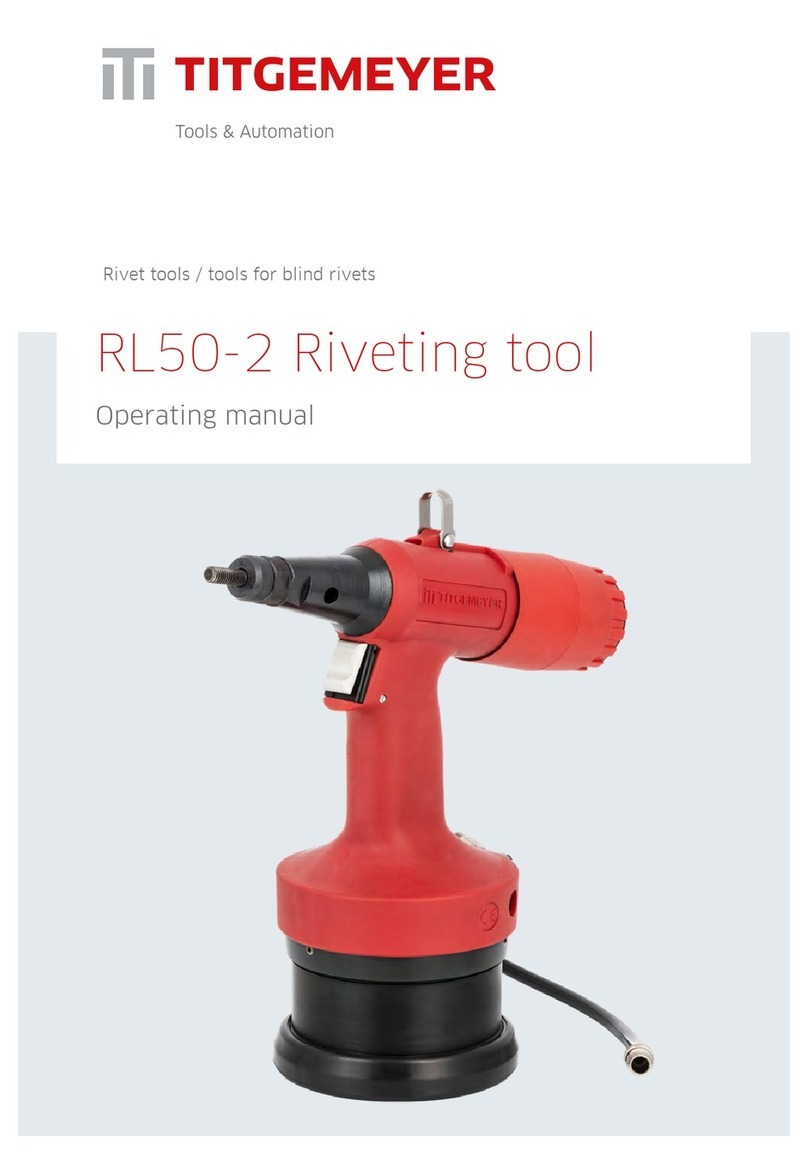
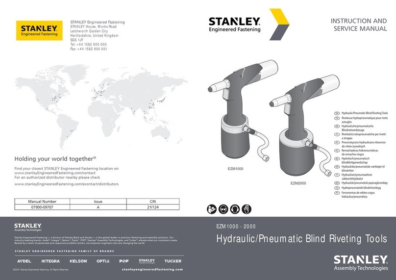
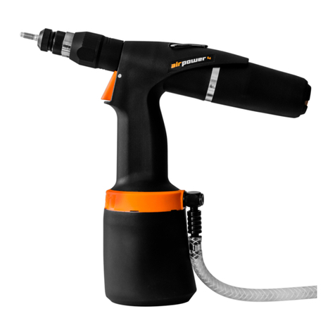
Titgemeyer RL100-2 User manual

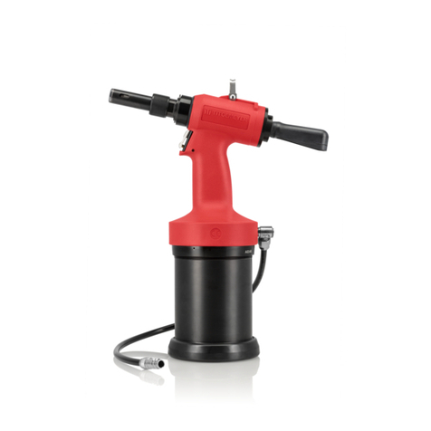
RL100-2 Riveting tool
Operating manual
Rivet tools / tools for blind rivets

2
RL100-2 / Manual
Titgemeyer / 10370EN0523 / 1
English
Content
1. Operating instructions 5
2. General description 5
3. Scope of use 5
4. Occupational health and safety 5
5. Safety measures 6
6. Specic safety instructions 6
7. Basic tool set-up 7
8. Commissioning 7
9. Tool operation 8
10. Intended use 9
11. Compressed air requirements 12
12. Storing the tool 12
13. Transportation instructions 12

3
RL100-2 / Manual
Titgemeyer / 10370EN0523 / 1
English
14. Operator requirements 13
15. Tool modications 13
16. Inspection schedule 13
17. Inspection and maintenance 14
18. Troubleshooting 16
19. Technical specications 16
20. Disposal of the riveting tool 16
21. Warranty 16
22. Package contents 17
23. Safety pictograms 18
24. Declaration of Conformity 20

4
RL100-2 / Manual
Titgemeyer / 10370EN0523 / 1
English

5
RL100-2 / Manual
Titgemeyer / 10370EN0523 / 1
English
1. Operating instructions
Please read these operating instructions
carefully prior to using the tool. Im-
proper use may cause the tool to work
incorrectly. All information and instruc-
tions contained in this document apply
to the specied tool and may only be
used for the purpose of operating this
particular tool.
Prior to adjusting, operating or servi-
cing this tool, the individuals concerned
must read and observe these operating
instructions. In certain cases, the seller
may offer and carry out training courses
as applicable.
To ensure that the tool can be operated
as intended, it is vital that all technical
and safety measures are followed..
2. General description
The RL100-2 is a high-speed, hydro-
pneumatic riveting tool designed to pre-
cisely install blind rivet nuts and blind
rivet studs. The spin action delivered
by the tool’s hydro-pneumatic system
enables rivets to be pre-assembled on
the mandrel and then detached.
The pull-to-force and pull-to-stroke
settings can be adjusted individually or
in combination to deliver the best-possi-
ble installation results regardless of the
eld of application.
This hydro-pneumatic tool is designed
for the installation of M6 to M16 blind
rivet nuts and M6 to M10 blind rivet
studs.
3. Scope of use
1Use pull-to-stroke to adjust
2Use pull-to-stroke, pull-to-force or combination of
both to adjust
3 Always check rst to see if the installation of M16
blind rivet nuts is possible
Always read these operating instructi-
ons prior to using this tool and observe
the applicable safety regulations.
4. Occupational health and safety
The following directions and principles
apply to the riveting tool described in
these operating instructions and to all
user groups.
Material Size of blind rivet nut
M6 M8 M10 M12 M14 M16
Aluminium,
brass
X1X1X1X2X2x2,3
Steel X1X1X2X2X2X2,3
Stainless steel X1X1X2X2X2X2,3
Material Size of blind rivet stud
M6 M8 M10 M12 M14 M16
Aluminium,
Brass
X1x1X1
Steel X1X1X2
Stainless steel X1X1X2

6
RL100-2 / Manual
Titgemeyer / 10370EN0523 / 1
English
Aside from the general directions outli-
ned in this segment concerning both the
tool and its use, additional safety ins-
tructions may be provided throughout
this document in respect of individual
items or components.
5. Safety measures
Fundamental safety measures for pre-
venting damage and injuries.
Improper use of the tool may result in
personal injury or property damage. To
avoid damage or injury, always follow
the corresponding safety instructions
and take the necessary safety precauti-
ons. Any maintenance, service or repair
work performed on the tool must only
be carried out by suitably qualied
personnel.
6. Specic safety instructions
This riveting tool has been designed
exclusively for installing blind rivet nuts
and blind rivet studs. The customer shall
be solely responsible for any modicati-
ons that are made to the riveting tool!
IMPORTANT!
— Do not use this tool before reading
and understanding these operating
instructions.
— Do not operate this tool if you are
unwell, if you have taken any form of
medication, or are under the inuence
of alcohol.
— Do not use the tool if parts are mis-
sing or there is discernible mechanical
damage.
— Never aim the riveting tool at any
individuals and only operate it when
in contact with a work piece.
— Only use the riveting tool within a
working temperature range of 5 °C to
no more than 45 °C.
— A maximum operating pressure of 7
bar must not be exceeded.
— Should the air pressure exceed the
max. 7-bar limit, use the appropriate
equipment to reduce it.
— Only use ttings and hoses with an
operating pressure rating of 10 bar
(compressed air).
— Prior to adjusting the tool settings or
replacing any components, always
disconnect the riveting tool from the
compressed air line.
— The recommended threaded man-
drels/internal threaded mandrels and
nosepieces must be chosen depending
on the blind rivet nut/blind rivet stud
diameters concerned.
— The prescribed personal protective
equipment should be used/worn at all
times.
— If not in use, the tool must always be
disconnected from the compressed air
supply.
— The tool must only be used to install
rivets.
— Do not use the tool without a nose-
piece and tted threaded mandrel/
internal threaded mandrel (5).
7
3
5
6
4
2
10
7
9
8
1
RL100-2 / Manual
Titgemeyer / 10370EN0523 / 1
English
— Never lift the riveting tool by the air
hose.
— Do not use the tool without a tted end
cap (10).
— The compressed air supply must be
lubricated or oil lled manually to pre-
vent any issues arising with the motor.
NOTE
The manufacturer shall not be liable for
any damage incurred due to improper
repair work or the use of non-original
spare parts.
The warranty shall be rendered invalid
if any repair work results in the riveting
tool or the seals becoming damaged.
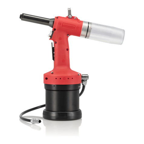
7. Basic tool set-up
Basic set-up – RL100-2:
1. Compressed air supply
2. Lifting attachment
3. Oil rell screw
4. Nose cap
5. Threaded mandrel/internal threaded
mandrel
6. Nosepiece
7. Trigger (rivet installation)
8. Trigger (to spin off threaded mandrel)
9. Force adjustment screw
10. Stroke adjuster (under housing)
Basic tool equipment
overview
8. Commissioning
Check the riveting tool visually before
commencing any work
— For visible damages
— For oil leaks
Test of the tool function without rivets
nuts prior processing –20 times (Tool
operation)

8
RL100-2 / Manual
Titgemeyer / 10370EN0523 / 1
English
Connecting the tool to
the air supply
Trigger (8) (to spin off the
threaded mandrel)
9. Tool operation
— Perform a functional test after inspec-
ting the tool or prior to using it for the
rst time (commissioning)
— Connect the tool to the air supply (6 to
7 bar)
— To prevent the tool from being dama-
ged due to an overly high supply of air
pressure, the integrated safety valve will
trigger and release air. If this occurs, ad-
just the air pressure to the correct value.
— Check that the quick connectors have
been correctly tted – no hissing (air
discharge) should be audible.
— Push the blind rivet nut onto the threa-
ded mandrel. This will start to rotate
automatically until the rivet is fully
situated on the mandrel.
— Be sure to hold the tool perfectly per-
pendicular (90°) to the surface of the
work piece.
— Press and hold the trigger (7): the rive-
ting tool will perform a pulling motion.
After nishing the riveting process, the
mechanism will automatically return to
its initial position and the mandrel will
spin off the blind rivet nut.
— If the blind rivet nut needs to be remo-
ved from the mandrel for whatever rea-
son, press the trigger (8) to activate the
spin off action: the threaded mandrel
will then spin off the blind rivet nut.

9
RL100-2 / Manual
Titgemeyer / 10370EN0523 / 1
English
— Each snap index on the stroke adjuster
(11) equates to a change of stroke of
roughly 0.08 mm.
— Each marking on the stroke adjuster is
equivalent to roughly 1 mm.
9.3 Setting the pull-to-force
— To adjust the pull-to-force, the stroke
adjuster (11) must be set to its maxi-
mum position (rotate anti-clockwise)
— First, set the pull-to-force to its lowest
value by turning the force adjustment
screw (9) anti-clockwise until it rea-
ches its end position
— Then screw on the blind rivet nut/blind
rivet stud by hand
— Perform a rivet installation test. If
correctly installed, the nut should not
deform. The blind rivet nut/blind rivet
stud should spin off from the mandrel/
internal mandrel automatically.
9.1 Set-up options: setting the pull-to-
stroke/pull-to-force
— The tool’s pull-to-stroke and pull-to-
force can be set individually or in
combination.
— If you want to use the riveting tool for
different clamping thicknesses without
having to adjust the tool settings, the
recommended approach would be to use
the “Setting the pull-to-force” option.
— The “Setting the pull-to-stroke" option is
ideal for use on smaller blind rivet nut
dimensions (M6 or M8) or if the rivets to
be used are made of soft materials.
— The pull-to-stroke setting is also re-
commended if working with a single
clamping thickness only.
— To set the pull-to-stroke and pull-to-
force in combination, please follow the
steps outlined below.
9.2 Setting the pull-to-stroke
— To activate the pull-to-stroke mecha-
nism, the force adjustment screw (9)
must rst be set to its maximum value.
To do this, rotate the force adjustment
screw (9) clockwise as far as it will go
(max. pulling force).
— Remove the end cap (10).
— Adjust the stroke by turning the stroke
adjuster (11): to reduce the stroke,
rotate clockwise; to increase the stroke,
rotate anti-clockwise.
Stroke adjuster (11)
End cap (10)
Stroke adjuster
(11) with stroke
setting rings
Force adjustment
screw (9)

10
RL100-2 / Manual
Titgemeyer / 10370EN0523 / 1
English
— Turn the force adjustment screw (9)
clockwise to increase the pull-to-force.
— After adjusting the pull-to-force, press
the trigger at least 5 times before
installing the next rivet.
— Check the outcome of the rivet ins-
tallation that results from the new
setting and repeat the entire process if
necessary while gradually increasing
the pull-to-force.
— Adjust to the required pull-to-force by
turning the adjustment screw clockwi-
se (+) or anti-clockwise (-) and perform
a rivet installation test each time until
the ideal setting is found and the blind
rivet nuts/studs deform as desired.
Pull-to-stroke and pull-to-force settings
in combination
A combination of both functions is espe-
cially advantageous whenever a high
pull-to-force should be achieved whilst
also protecting the threaded mandrel as
well as the internal thread of the rivet
nut.
It is also the recommended choice in the
case of small-diameter blind rivet nuts/
blind rivet studs or blind rivet nuts/blind
rivet studs made from soft materials.
— First, adjust the pull-to-stroke setting
as desired by following the steps outli-
ned under “Setting the pull-to-stroke”.
— Then adjust the pull-to-force by
turning the force adjustment screw (9)
as needed (clockwise to increase the
pull-to-force; anti-clockwise for less
pull-to-force) until you achieve the
ideal pull-to-force setting for the rivet
installations you wish to perform.
10. Intended use
To ensure compliance with all of the
relevant safety measures and that the
riveting tool will work correctly, the fol-
lowing requirements must be fullled:
— The tool must only be used in compli-
ance with the dened technical spe-
cications and all specications con-
cerning the use, assembly, connection
of the tool as well as the permissible

11
RL100-2 / Manual
Titgemeyer / 10370EN0523 / 1
English
environmental and working conditi-
ons observed. These specications
and conditions, along with all infor-
mation concerning use of the tool, are
stipulated in the documents as well as
the operating and maintenance ins-
tructions contained in the operating
manual supplied with the tool.
— The tool may only be operated in
compliance with the relevant local
regulations and tool-specic condi-
tions, in particular the specications
and potential hazards that need to be
observed when using the tool.
— All measures related to the proper
upkeep of the tool, e.g. transportation
and storage, maintenance and regular
inspection, must be observed.
— Only use quick-release safety cou-
plings if the compressed air hose is
to be permanently connected to the
compressed air source.
— Always apply the riveting tool at right
angles (90°) to the rivet installation
assembly surface.
Compressed air supply
— To ensure the proper operation of
the tool, the minimum/maximum
permissible input pressure rating of
6-7 bar must always be maintained. A
suitable pressure reducing valve must
be used where appropriate. Failure to
maintain the specied pressure may
result in personal injury or property
damage.
— The pressure regulator must be
equipped with a lter unit to collect
any dirt particles or condensate. If
the pressure regulator tted does not
incorporate a lter unit, precautions
must be taken to ensure that the
compressed air is free from any dirt
particles and/or condensation.
— We recommend using an automatic
lubrication unit in the compressed air
system. If an automatic air lubrication
unit cannot be used, 3 drops of oil
must be added to the device manually
each hour that the tool is in opera-
tion. The pneumatic motor may seize
up otherwise. A seized-up motor shall
not constitute grounds for complaint.
— The distance between the air supply
pressure regulator and the riveting
tool must not exceed 3m.
— The supply line must be resistant to
oil and other liquids and be of a sui-
table quality for the conditions under
which it is required to operate.
— The internal diameter of the air hose
must be no less than 6 mm.
— The maximum achievable pull-to-force
will depend on the permissible input
pressure being maintained.

12
RL100-2 / Manual
Titgemeyer / 10370EN0523 / 1
English
11. Compressed air requirements
ISO 8573-1
12. Storing the tool
After rst use
If you are not going to use the riveting
tool any further, store it away in its ori-
ginal packaging in a clean and dust-free
place.
After long-term storage
After long-term storage (about 3 years),
replace the hydraulic oil before use. The
hydraulic oil may only be replaced by
a trained specialist and in compliance
Compressed air
quality classes ISO
8573-1
Solids Water Oil
Maximum
size
µm
Maximum
concentration
mg/m3
Maximum
pressure dew point
°C
Maximum
concentration
mg/m3
2 1 1 -40 0.1
Note: The stated maximum concentrations relate to 1 bar abs., +20 °C and 60% rela-
tive humidity. The more the pressure exceeds the atmospheric pressure, the greater
the individual concentrations.
with the operating instructions. Where
needed, please contact a Titgemeyer
service centre for professional advice
and assistance.
13. Transportation instructions
The riveting tool is delivered fully
assembled. It needs to be handled with
care. This product contains hydraulic oil.

13
RL100-2 / Manual
Titgemeyer / 10370EN0523 / 1
English
14. Operator requirements
All planning, assembly, installation,
commissioning, maintenance and repair
work must only be performed by skilled
personnel and subsequently inspected
by a suitably qualied expert. Training
can be provided by the manufacturer by
arrangement.
The occupational health and safety spe-
cialists must ensure the following:
— All safety-related work tasks must
only be performed by suitably quali-
ed personnel.
— Personnel must be suitably qualied
for the respective specialist tasks to
be conducted (training, education,
experience) or be familiar with the
relevant standards, specications,
accident prevention regulations and
system properties. It is essential that
these specialists are capable of iden-
tifying and preventing any potential
risks in a timely manner.
15. Tool modications
No structural modications that could
negatively affect the safety of the tool
may be performed on the tool without
the manufacturer’s consent. Any impro-
per repairs or the use of non-original
spare parts are deemed to constitute an
improper structural modication of the
tool. In such instances, the manufactu-
rer can no longer guarantee the proper
operation of the tool and the product
warranty will be voided. The warranty
shall equally not apply to the tool in the
event that any seals are damaged.
Risk of injury due to improper handling!
This tool can be operated safely if the
regulations and requirements contained
in this manual have been read, unders-
tood and followed. The operator must
observe the procedures described in this
manual. Any maintenance and repair
work not described in this operating
manual may only be performed by per-
sonnel who have received the required
training from TTA’s training specialists.
16. Inspection schedule
Inspection intervals
— Daily inspection
— Check for oil leaks
— Check for unexpected air leakage
— Check that the tool is working
properly and correctly installing
the rivets
— Check that the settings are correct
and the riveting mechanism is
properly secured
— Check the nosepiece (6) and
threaded mandrel/internal
threaded mandrel (5) for any wear
and tear or dirt and replace any
contaminated, damaged or worn

14
RL100-2 / Manual
Titgemeyer / 10370EN0523 / 1
English
parts as needed.
— Stop using the tool immediately if
you notice any signs of apparent
defects or damage.
— Weekly inspection/ after 5.000 cycles
— Check the nosepiece (6) and threa-
ded mandrel/internal threaded
mandrel (5) for any wear and tear
or dirt and replace any contami-
nated, damaged or worn parts as
needed.
— Rell with oil as needed.
— Full inspection to be performed by
authorised personnel (or the manu-
facturer) once a year or after 500,000
cycles
— Comprehensive inspection and ser-
vicing of the riveting tool mecha-
nism
— Inspection of all parts for wear and
tear and replacement as needed
— Oil change
Do not use any highly active cleaning
agents or ammable liquids when clea-
ning the tool!
The riveting tool must be cleaned and
checked for mechanical defects prior to
each use. If storing the tool for an exten-
ded period, rst clean the tool and then
apply a thin layer of corrosion-inhibiting
grease to all external metal parts.
17. Inspection and maintenance
Nosepiece assembly and disassembly
— Disconnect the tool from the compres-
sed air supply.
— Replace both the nosepiece (6) and
nose cap (4) using a size 20 mm hex
wrench.
— If tting a different-sized nosepiece
(6), the appropriate threaded man-
drel/internal threaded mandrel (5)
will also need to be tted. Two size
13 mm hex wrenches will be needed
to perform this task.
Changing the mandrel
— Disconnect the tool from the compres-
sed air supply.
— Disassemble the nosepiece (6) and
counter nut (6a) from the nose cap (4)
using two size 27 mm hex wrenches
— Remove the nose cap (4) using a size
30 mm hex wrench size.
— Replace the threaded mandrel (5)
using two size 13 mm hex wrenches
and tighten with the safety nut (5a).
— Reassemble the tool by following the
above steps in reverse.
5a
5
4
6
6a

15
RL100-2 / Manual
Titgemeyer / 10370EN0523 / 1
English
— Make sure that all of the components
are secured in place by the tightened
counter nuts.
— The nosepiece (6) then needs to be
adjusted to its correct position (See
“Adjusting the nosepiece”).
— Re-connect the tool to the compressed
air supply.
Adjusting the nosepiece
— To ensure that the tool delivers the
right results, the nosepiece (6) must
be adjusted to the length of the blind
rivet nut.
— Correct setting: At least 1 thread of
the mandrel (5) protrudes from the
blind rivet nut.
— Adjust the position of the nosepiece
(6) by turning it in the desired direc-
tion.
— Secure the nosepiece (6) to the nose
cap (4) using the counter nut (6a) and
two size 27 mm or 30 mm hex wren-
ches.
Oil rell
— Rell with oil if you notice a loss of
stroke during the rivet installation
process.
— When relling with oil, make sure that
no dirt is able to enter the hydraulic
system.
— Disconnect the tool from the compres-
sed air supply.
— Remove the nose cap (4), including
the nosepiece (6 and 6a).
— Use a size 4 Allen key to remove the
screw at the top of the tool.
— Fill the oil transfer syringe with the
recommended hydraulic oil (See
“Technical specications”) and place it
over the brass ll screw. Then screw
the adapter onto the ll screw outlet.
— Squeeze the hydraulic oil into the tool
by pump the syringe piston multiple
times. While pumping, the hydraulic
piston will move forwards and back-
wards.
— Remove the ll screw and re-attach
the cylinder screw and USIT ring.
Then t the nose cap.
— Wipe off any oil that may have spilled
onto the tool.
— Perform a functional test (20 dummy
installations without rivets) before
using the tool.
Oil rell screw with USIT ring
Threaded mandrel
protrusion

16
RL100-2 / Manual
Titgemeyer / 10370EN0523 / 1
English
18. Troubleshooting
The operator must ensure the following:
— Maintenance personnel must be readi-
ly available at all times.
— Maintenance personnel are qualied
to properly respond to and remedy
riveting tool malfunctions as well as
malfunctions in related systems.
— All malfunctions/failures are analysed
by suitably qualied personnel, any
defects are repaired and the opera-
tion is optimised in such a way that a
repetition of such malfunctions/failu-
res is avoided in the future.
19. Technical specications
Total weight
(model-dependent)
2.64 kg
Dimensions (H x L) 298 x 342 mm
Blind rivet nut diameter M6 – M16
Pull-to-force 15 – 36 kN / 6 bar
Stroke 12 mm
Speed of riveting cycle 0.9 s
Air consumption per rivet 5.8 l [ANR]
Noise level 89 dB at 6 bar
Operating pressure 6 bar, max. 7 bar
Compressed air connection 6 mm (G 1/4”)
Hydraulic oil standard ISO HN 32
Sample hydraulic oil product: OH-HM 32
Lubricant standard ISO XCCHB-2
Sample lubricant product: LV2EP
20. Disposal of the riveting tool
Dispose of the tool in compliance with
the EU directives. Check for hydraulic oil
inside the riveting tool. Remove any oil
and dispose of it in compliance with the
environmental regulations.
21. Warranty
Titgemeyer GmbH & Co. KG provides a
12-month warranty from the date of
purchase. The warranty does not cover
consumables (jaws, nosepieces, man-
drels, etc.).
Titgemeyer GmbH & Co. KG warrants
that all power tools have been carefully
manufactured and that no defects in ma-
terial or workmanship will arise under
normal use of the tool for a period of
one (1) year. This warranty only applies
to the initial purchaser of the tool and is
subject to the tool only being used for
its original intended purpose.
Warranty exclusions: normal wear and
tear. Periodic maintenance and repair
work as well as replacement parts
needed due to the normal wear and tear
of parts/components are excluded from
the warranty coverage. Improper use.
Defects or damage resulting from the
improper use/operation, storage, misuse,
accidents or neglect, such as physical
damage to the tool, are excluded from
coverage. Unauthorised maintenance/
service work or modications. Defects

17
RL100-2 / Manual
Titgemeyer / 10370EN0523 / 1
English
or damage resulting from maintenan-
ce/service work, testing adjustments,
assembly, repair work, alterations or
modications of any kind performed by
anyone other than Titgemeyer GmbH &
Co. KG or its authorised service centres
are hereby excluded from the warranty
coverage.
Should this tool fail to be up to the war-
ranty’s valid standards, promptly return
the tool to our Titgemeyer GmbH & Co.
KG service centre or the factory authori-
sed service centre location nearest you.
Titgemeyer GmbH & Co. KG will then
replace, free of charge, any part or parts
found by us to be defective due to faul-
ty materials or workmanship and return
the repaired tool to you. This represents
our sole obligation under this warranty.
Under no circumstances shall Titge-
meyer GmbH & Co. KG be liable for any
consequential or special damages arising
from the purchase or use of this tool
22. Package contents
— 1 x RL100-2 riveting tool
— 1 x M8 mandrel
— 1 x M10 mandrel
— 1 x M12 mandrel
— 1 x M8 nosepiece
— 1 x M10 nosepiece
— 1 x M12 nosepiece
— 1 x No. 4 Allen key
— 1 x oil transfer syringe
— 1 x ll screw

18
RL100-2 / Manual
Titgemeyer / 10370EN0523 / 1
English
23. Safety pictograms
Wear protective goggles
Wear protective gloves
Wear ear protection

19
RL100-2 / Manual
Titgemeyer / 10370EN0523 / 1
English
DECLARATION OF CONFORMITY
Product Name: Riveting tool RL100-2
Catalogue Number: 99-0306:TTA
Type number: 99030602012021
The riveting tool RL100-2 works with the high-speed hydro-pneumatic principle. The tool is designed for the
precise setting of blind rivet nuts and blind rivet screws. The riveting tool is equipped with a pneumatic-
hydraulic system for performing the screwing process for pre- and disassembling the rivet with or from the
mandrel. screwing Adjustment of the pulling force, the stroke and a combination of both is possible with this
tool to set up the best conditions for the riveting situation.
The high-speed pneumatic-hydraulic tool is designed for setting blind rivets nuts from M6 to M16 and blind
rivet screws from M6 to M10.
Manufacturer:
Titgemeyer Tools & Automation spol. s r.o.
U Vodárny 1506
CZ 397 01 Písek
IČ 60647761
Tel: + 420 382 206 711
info@rivetec.cz
tta-sales@titgemeyer.com
We hereby declare that the products conform to
the following standards and guidelines:
2006/42/ES, the Machinery Directive
Name Date and place Signature
Approved by
Director
Antonín Solfronk
In Písek
31.03.2021
1 / 1

Titgemeyer Tools & Automation spol s.r.o.
U Vodárny 1506
39701 Pisek
Tschechien
T + 420 382 206 711
E tta-sales@titgemeyer.com
W titgemeyer.com
Table of contents
Other Titgemeyer Rivet Tools manuals

Titgemeyer
Titgemeyer RL50-2 User manual

Titgemeyer
Titgemeyer RL20-2 User manual

Titgemeyer
Titgemeyer MS 50 User manual

Titgemeyer
Titgemeyer MS 40A User manual

Titgemeyer
Titgemeyer TIOS HN12 PT User manual

Titgemeyer
Titgemeyer RL60-2 User manual

Titgemeyer
Titgemeyer RIVETEC RL 50 User manual

Titgemeyer
Titgemeyer RIVETEC RL 75 User manual

Titgemeyer
Titgemeyer RL75-2 User manual