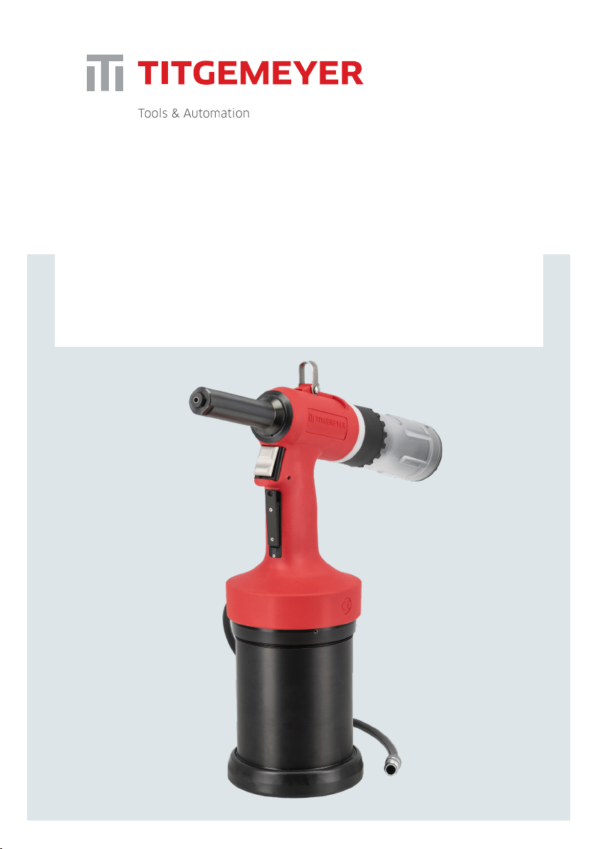
Titgemeyer RL60-2 User manual

RL60-2 Riveting tool
Operating manual
Rivet tools / tools for blind rivets

2
RL60-2 / Manual
Titgemeyer / 10342EN1121 / 1
English
1. Operating instructions 5
2. General description 5
3. Scope of use 5
4. Occupational health and safety 8
5. Safety measures 8
6. Special safety advice 8
7. Basic tool equipment 9
8. Commissioning 9
9. Tool operation 10
10. Proper use 11
11. Requirements for compressed air 12
12. Riveting tool storage 12
Content

3
RL60-2 / Manual
Titgemeyer / 10342EN1121 / 1
English
13. Transport Instructions 13
14. Requirements for operators 13
15. Tool modications 13
16. Inspection plan 13
17. Inspection and maintenance 14
18. Troubleshooting 17
19. Technical parameters 17
20. Disposal of the riveting tool 17
21. Warranty 17
22. Package contents 18
23. List of Safety Pictograms 18
24. EC Declaration of conformity 19

4
RL60-2 / Manual
Titgemeyer / 10342EN1121 / 1
English

5
RL60-2 / Manual
Titgemeyer / 10342EN1121 / 1
English
1. Operating instructions
Read the operating instructions carefully
prior to use. Improper use may cause
the tool to work incorrectly. All infor-
mation and instructions apply to the
specied tool and may only be used for
the purpose of operating the tool.
All persons that adjust, operate or ser-
vice the tool have to become familiari-
zed with the operating instructions and
have to follow them. In special cases, a
training can be organized by the seller.
The professional and safety measures
must be followed in order to ensure that
the tool works properly.
2. General description
The RL60-2 riveting tool works with the
high-speed hydro-pneumatic principle.
The tool is designed for precise setting
of blind rivets. It is equipped with a
vacuum system for holding the rivet
in the nosepiece in any position. After
riveting the mandrel will be collected in
the mandrel collector.
The high-speed pneumatic-hydraulic
tool is designed for setting one-sided
blind rivets from 4 to 6,4 mm and 6,4
mm structural rivets. The tool is suita-
ble for multi-grip blind rivets and blind
rivets with soft materials.
The operating instructions must be read
by every person using this tool. Pay
attention to the safety regulations.
3. Scope of use
For choosing the correct tooling setup
for the assembly of the used rivet type
and size, please refer to the separately
provided equipment guide of this tool.
Size of rivets 4 4,8/5 6 6,4 6,4 –
Structural
Rivets
Material Aluminium X X X X X
Steel X X X X X
Stainless x x x X x

6
RL60-2 / Manual
Titgemeyer / 10342EN1121 / 1
English
4. Occupational health and safety
The following instructions and directives
apply to the riveting tool described in
these operating instructions and to all
user groups.
In addition to the general instructions
in this chapter that concerns the entire
document and all procedures of using
the riveting system, some parts of this
document may contain additional safety
instructions which then specically rela-
te to the described matter.
5. Safety measures
Basic safety measures to avoid damages
and injuries.
Improper use of the tool may lead to
an injury or damage of property. To
avoid damages, always adhere to the
corresponding safety instructions of the
safety measure. Only qualied staff are
authorized to perform maintenance and
repairs of the tool.
6. Special safety advice
The riveting tool is exclusively designed
for setting blind rivets. The Customer
bears individual responsibility for each
and every change of the riveting tool!
ATTENTION!
— Use the tool only after reading and un-
derstanding the operating instructions.
— Do not operate with the tool if you are
ill, under the inuence of drugs, alcohol.
— Do not use the tool when it is incom-
plete and when it has visible mecha-
nical defects.
— Never aim the riveting tool at people
and do not rivet without material.
— Use the riveting tool only at working
temperature ranging from 5°C to 45°C.
— Never get over the maximum limit of
input air-pressure of 7 bar
— In case the provided air pressure
exceeds the max of 7 bar, use appro-
priate equipment to reduce it.
— Use only ttings and hoses for an
approved operating pressure of 10
bar in pneumatics.
— When adjusting or replacing com-
ponents, always disconnect the tool
from the compressed air supply
— For the used rivet diameter, use the
suitable nosepiece (5) accordingly.
— Always use personal protective equip-
ment.
— Tool not in current use must not be con-
nected to the compressed air supply
— Use the tool only for riveting
— Do not use the tool without assem-
bled nosecap (6).
— The riveting tool must not be carried
or lifted by the air hose
— Make sure, the suction system is not
activated, while disassembling the
mandrel collector (2), for emptying.

7
3
5
64
2
7
8
1
RL60-2 / Manual
Titgemeyer / 10342EN1121 / 1
English
ATTENTION!
Make sure that the mandrel collector is
always attached on the riveting tool when
in use, otherwise there is a risk of injury.
NOTE
The Manufacturer bears no liability for
damages incurred due to incorrect repair
or due to using spare parts from other
sources.
The warranty is deemed invalid in case
of any repairs have been performed on
the riveting tool, leading to the damage
of the riveting tool or the seals.
7. Basic tool equipment
Overview of RL60-2 basic tool
equipment:
1. Air connection
2. Mandrel collector
3. Balancer suspension attachment
4. Screw for oil rell
5. Nosepiece
6. Nosecap
7. Trigger
8. Air suction trigger Basic tool equipment
overview

8
RL60-2 / Manual
Titgemeyer / 10342EN1121 / 1
English
8. Commissioning
Check the riveting tool visually before
commencing any work
— For visible damages
— For oil leaks
Check the nose cap is tightened to the
house head and select the correct nose-
piece for the rivet being used
Test of the tool function without rivets
prior processing –20 times
(Tool operation)
9. Tool operation
— After inspection before rst use (com-
missioning)
— Connect the tool to the air supply (6
– 7 bar)
— To avoid damage to the tool, caused
by exceeded air pressure, the integra-
ted safety valve will switch to release
air. In this case, adjust the air pressure
to the correct value
— Check for correct assembly and t of
the quick connectors – no air dischar-
ge is audible
— Press and hold the air suction trigger
(8)– the riveting tool starts soaking air
though the nosepiece.
— Insert the mandrel of the rivet in the
nosepiece (5) (the rivet will be held in
nosepiece by the air ow).
— Move the tool with rivet to the alloca-
ted riveting position.
— Press the trigger (7) – the riveting
tool performs the pulling movement
(pulling and tearing the mandrel)
— Release the trigger (7) after setting
the rivet and the pulling unit auto-
matically returns to its initial starting
position
— Hold the air suction trigger (8) during
the riveting cycle to eject the ripped
off mandrel into the mandrel collector
(2).
— Make sure, the mandrel is ejected
before the next riveting cycle.
— Release the air suction trigger (8),
to switch off the air suction ow or
continue with the next cycle.
Connecting the tool
with the air supply

9
RL60-2 / Manual
Titgemeyer / 10342EN1121 / 1
English
10. Proper use
To ensure that all the corresponding
safety measures are observed and that
the riveting tool will work properly, the
following is required:
— The system has to be used in compli-
ance with the tool’s technical data and
specications concerning the use, as-
sembly, connection, environment and
work conditions. These conditions are
stipulated in the documents related to
the order, user information (tags etc.)
and in the documentation delivered
with the system, which includes the
operating instructions, as well as the
maintenance and inspection instruc-
tions in this manual.
— The users have to act in compliance with
local and system-specic conditions
and pay corresponding attention to the
operating hazards and specications.
— All measures required for the main-
tenance of the tool, e.g. transport and
storage, as well as the requirements
for maintenance and regular inspec-
tion must be observed.
— Use only a safety quick coupler for
permanent connection to the com-
pressed air sources
— The mandrel collector must always
be emptied as soon as it exceeds half
load capacity
— Always set the riveting tool at the
right angle (90°) to the assembly
surface
Perpendicular positioning
of the tool to the surface
K= clamping
thickness
Compressed air supply
— For correct operation of the device,
it is necessary to observe the range
of inlet air pressure between the
minimum and maximum permissible
value of 6 – 7 bar. If necessary an
appropriate pressure reduction valve
has to be used. In case of non-com-
pliance, personal injury or damage to
the device may occur.
— The pressure regulator must be equip-
ped with a lter unit for separating
dirt and condensate from the air
supply. In case the pressure regulator
with a lter unit will not be used, it
must be ensured that the compressed
air cannot contain any dirt and/or
condensate.
— The length between the air supply
pressure regulator and the tool must
not exceed 3m.
— Used air supply hose must be re-
sistant to oil, liquids and operating
conditions
— Used air hoses must have a 6 mm
minimum inner diameter.
— Achieving the maximum force of the
tool depends on compliance of the air
inlet pressure

10
RL60-2 / Manual
Titgemeyer / 10342EN1121 / 1
English
12. Riveting tool storage
Before the rst use
If you are not going to use the riveting
tool any further, place it in the original
packaging and store it in a dry and dust
free environment.
Air quality classes
under ISO 8573-1
Solid particles Water Oil
Maximum
size
µm
Maximum
concentration
mg/m3
Maximum
pressure dew point
°C
Maximum
concentration
mg/m3
2 1 1 -40 0.1
11. Requirements for compressed air
ISO 8573-1
Note: The stated maximum concentrations relate to 1 bar abs., +20°C and 60%
relative humidity. The individual concentrations are proportionally higher when the
pressure is higher than atmospheric pressure.
After long-term storage
After long-term storage (about 3 years),
replace the hydraulic oil before use. The
hydraulic oil may only be replaced by a
trained expert, according to the opera-
ting instructions. If required, you can
contact the Titgemeyer service center
for a professional service.

11
RL60-2 / Manual
Titgemeyer / 10342EN1121 / 1
English
13. Transport instructions
The tool is delivered completely
assembled. It has to be handled as
fragile equipment. This product contains
hydraulic oil.
14. Requirements for operators
All planning, assemblies, installations,
activations, maintenance and repairs
may only be performed by trained staff
and inspected by technical experts. Trai-
ning may be provided by the manufac-
turer by agreement.
The persons responsible for labour safe-
ty must ensure the following:
— All works related to safety are only
performed by qualied staff.
— The staff must be qualied on the
basis of their specialization (training,
education, experience) or on the basis
of their knowledge of corresponding
standards, specications, accident-
prevention regulations and system
properties. It is essential that such
persons are capable of identifying
and avoiding any potential risks in
timely manner.
15. Tool modications
No structural with this tool may not be
dangerous for the operator, when the re-
gulations in this manual have been read,
understood and followed. The operator
must follow the operations described
in this document. The maintenance and
service work that is not described in
these operating instructions may only
be performed by trained experts who
are trained by TTA.
Risk of injury in case of incorrect
manipulation!
Working with this tool may not be dan-
gerous for the operator, when the regu-
lations in this manual have been read,
understood and followed. The operator
must follow the operations described
in this document. The maintenance and
service work that is not described in
these operating instructions may only
be performed by trained experts who
are trained by TTA.
16. Inspection plan
Intervals of inspection plans
— Daily inspection
— Check for oil leaks
—
Check for unexpected air exhaustion
— Check if the tool works well and
performing a correct setting process

12
RL60-2 / Manual
Titgemeyer / 10342EN1121 / 1
English
— Check correct setting and tightening
of riveting mechanism
— Check if the nosepiece (5) is worn –
in case of visible wear replace the
nosepiece
— Check that the mandrel collector (2)
is assembled correctly.
— Stop using the tool immediately
when you notice any sign of a fault.
— Weekly inspection/ after 5.000 cycles
— Check the nosepiece (5) and jaws,
clean or exchange the contamina-
ted/destroyed and worn parts.
— Rell the oil, if necessary
— Complete inspection made by authori-
sed person (or by producer) once per
year/ or after 500.000 cycles
— Complete check and service of the
tool mechanism
— Inspection and change any worn
parts
— Perform oil change
Do not use any highly active cleaning
agents or ammable liquids when
cleaning!
The riveting tool must be cleaned and
checked in case of any mechanical
defects as for the corresponding type of
application. After the riveting tool has
been cleaned to be stored for a longer
period of time, all external metal parts
need to be lightly greased with corro-
sion inhibitor.
17. Inspection and maintenance
Jaws cleaning or replacement
Jaws need to be cleaned once a day or
after 2,000 rivets (depends on the rivet
quality). In case of larger amounts of
processed rivets, cleaning is performed
as needed. The grips are subject to me-
chanical wear and have to be replaced
as soon as they start slipping when the
rivet mandrel is held.
— Disconnect the tool from the compres-
sed air supply
— Loosen the front nosecap by wrench
no. 19, unscrew and carefully remove it
— Release the galvanized lock by pulling
towards the tool and unscrew the
clamping head
— Remove the jaws from the clamping
head. Clean the head and the jaws,
remove any chips in the spring and
the spring guiding or replace the parts
when worn or damaged
— Lightly grease the new jaws on the
outer circumference and insert them
(teeth to the axis) in the jaw case.
Screw the head back on the adap-
ter. The lock automatically secures
the clamping head against release.
Tighten only to the last possible tooth
of the lock. Do not use a wrench for
tightening! It could damage the lock
— Carefully screw on the front nosecap
and tighten it with wrench no. 19.
— Check the x-dimension value (chapter
18. Setup of the X-dimension)

13
RL60-2 / Manual
Titgemeyer / 10342EN1121 / 1
English
Nosepiece disassembly and assembly
Disconnect the tool from the compres-
sed air
Use wrench no. 19 to hold the tool’s no-
secap by the ats at the front and loo-
sen the nosepiece using wrench no. 11.
Then loosen the entire nosecap using
Jaw case
Nosecap
Galvanized
lock
Disassembly of
the nosecap
Assembly of the nosepiece
and nosecap
Disassembly of
the jaws
wrench no. 19. Remove the nosecap and
manually unscrew the nosepiece.
Take the selected nosepiece and manu-
ally screw it onto the removed nosecap.
Mount the nosecap back onto the tool
and tighten with wrench no. 19 (ats)
and no. 11 (nosepiece)

14
RL60-2 / Manual
Titgemeyer / 10342EN1121 / 1
English
Setup of the X-dimension
To achieve a good grip of the jaws with
the mandrel and just enough opening to
allow a smooth and not scratching inserti-
on of the mandrel in the tool, the correct
setup of the x-dimension is relevant. The
rst setting is performed by the manufac-
turer to x=84mm (basic setting).
If it is necessary, adjust the x-dimen-
sion by counter nut and spacer by using
wrenches no. 15 and 12. Maximum
allowed X-dimension is 86 mm with
default nosepiece and pulling head.
Minimum X-dimension is limited by the
thread on the piston. With higher size of
X-dimension it is possible to reach wider
jaw opening in case the rivet mandrel
gets stuck in the jaws. On the other
hand with lower X-dimension the jaws
may grip the mandrel faster.
This is advantageous in situation where
the mandrel is short and the jaws grip
it in the back. It is always necessary
to check if the pulling head does not
collide with the nosepiece to prevent
any damage.
Oil relling
— Oil needs to be relled when the wor-
king stroke is reduced during working
process
— During oil relling, prevent dirt from
entering the hydraulic system
— Disconnect the tool from the compres-
sed air
— Remove the nosecap (see chapter
jaws cleaning and replacement)
— Use allen key no. 4 to unscrew the
screw in the top of the tool
— Fill up the syringe with the recommen-
ded hydraulic oil (chapter 19. Technical
parameters), attach it to the brass adap-
ter and screw the adapter on the outlet
— Press the hydraulic oil into the tool
and pump the syringe piston several
times. As you are pumping, you can
see that the hydraulic piston is mo-
ving forward and backwards.
— Unscrew the adapter, mount the screw
and USIT ring, mount the nosecap (see
chapter jaws cleaning and replacement)
— Clean the tool from any spilled oil
— Activation of the tool without rivets -
SpacerCounter nut
X-dimension, basic setup
Disassembly of the oil rell screw

15
RL60-2 / Manual
Titgemeyer / 10342EN1121 / 1
English
Total weight (according to the
version)
1,99 kg
Dimensions (HxL) 331 x 336 mm
Blind rivet diameter 4 – 6,4 mm, max. Ø of
mandrel 4mm
Tractive force 17,9 kN / 6 bars
Stroke 27 mm
Speed of rivet cycle 1 s
Air consumption for 1 rivet 5,8 l [ANR]
Air consumption - exhaustion 465.5 l/min [ANR]
(78 l/min @6 bar)
Noise level 85,5 dB
Operating pressure 6 bars, max. pressure 7 bar
Compressed air connection 6 mm (G 1/4“)
Hydraulic oil standard ISO VG 32, HLP (DIN 51524-2)
Hydraulic oil example OH-HM 32
Lubricant standard ISO XCCHB-2
Lubricant example LV2EP
20. Disposal of the riveting tool
Disposal of the tool in compliance with
the directives valid for EU. Check for
hydraulic oil inside the riveting tool.
Remove it and dispose the oil in an
environmentally friendly manner.
21. Warranty
Titgemeyer GmbH & Co. KG provides a
12- month warranty from the date of
purchase. The warranty does not cover
consumables (jaws, nosepieces, man-
drels, etc.)
Titgemeyer GmbH & Co. KG warrants
that all power tools have been carefully
manufactured and that they will be free
from defect in material and workmans-
hip under normal use and service for
a period of one (1) year. This warranty
applies to the rst time purchaser of the
tool for original use only.
Exclusions: Normal wear and tear. Perio-
dic maintenance, repair and replacement
parts due to normal wear and tear are
excluded from coverage. Abuse & misu-
se. Defect or damage that results from
improper operation, storage, misuse or
abuse, accident or neglect, such as phy-
sical damage are excluded from cover-
age. Unauthorized service or modica-
tion. Defects or damages resulting from
service, testing adjustment, installation,
20 times (Tool operation)
18. Troubleshooting
The operator must ensure the following:
— The maintenance staff can be notied
immediately and at any time.
— The maintenance staff is qualied to
properly respond to the failure of the
riveting tool and the failure of related
systems.
— The failures are analysed by qualied
staff, any defects are repaired and the
operation is optimised in a way that
prevents any similar failures in the
future.
19. Technical parameters

16
RL60-2 / Manual
Titgemeyer / 10342EN1121 / 1
English
— 1 x syringe
— 1 x adapter
23. List of safety pictograms
Use protective goggles
Use protective gloves
Use ear protection
maintenance, alteration or modication
in any way by anyone other than Tit-
gemeyer GmbH & Co. KG, or its authori-
zed service centres, are excluded from
coverage.
Should this tool fail to meet the war-
ranty, promptly return the tool to our
Titgemeyer GmbH & Co. KG service cen-
ter or factory authorized service centre
location nearest you.
Titgemeyer GmbH & Co. KG will then
replace, free of charge, any part or
parts found by us to be defective due
to faulty material or workmanship, and
return the tool repaired. This represents
our sole obligation under this warranty.
In no event shall Titgemeyer GmbH &
Co. KG be liable for any consequential
or special damages arising out of the
purchase or use of this tool.
22. Package contents
— 1 x riveting tool
— 1 x air supply connection
— 1 x Nosepiece No. 4
(Ø 4mm standard blind rivets)
— 1 x Nosepiece No. 3 (Ø 4,8mm/
5,0mm standard blind rivets)
— 1 x Nosepiece No. 2
(Ø 6mm standard blind rivets)
— 1 x Nosepiece No. 1
(Ø 6,4mm standard blind rivets)
— 1 x Allen key no. 4
— 1 x open single-end wrench SW11

17
RL60-2 / Manual
Titgemeyer / 10342EN1121 / 1
English
DECLARATION OF CONFORMITY
Product Name: Riveting tool RL60-2
Catalogue Number: 99-0304:TTA
Type number: 99030402012021
The RL60-2 riveting tool works with the high-speed hydro-pneumatic principle. The tool is designed for
precise setting of blind rivets. It is equipped with a vacuum system for holding the rivet in the nosepiece in
any position. After riveting the mandrel will be collected in the mandrel collector.
The high-speed pneumatic-hydraulic tool is designed for setting one-sided blind rivets from 4,0 to 6,4 mm
and 6,4 mm structural rivets.
Manufacturer:
Titgemeyer Tools & Automation spol. s r.o.
U Vodárny 1506
CZ 397 01 Písek
IČ 60647761
Tel: + 420 382 206 711
info@rivetec.cz
tta-sales@titgemeyer.com
We hereby declare that the products conform to
the following standards and guidelines:
2006/42/ES, the Machinery Directive
Name Date and place Signature
Approved by
Director
Antonín Solfronk
In Písek
31.03.2021
1 / 1

18
RL60-2 / Manual
Titgemeyer / 10342EN1121 / 1
English

19
RL60-2 / Manual
Titgemeyer / 10342EN1121 / 1
English

Titgemeyer Tools & Automation spol s.r.o.
U Vodárny 1506
39701 Pisek
Tschechien
T + 420 382 206 711
E tta-sales@titgemeyer.com
W titgemeyer.com
Table of contents
Other Titgemeyer Rivet Tools manuals

Titgemeyer
Titgemeyer RL50-2 User manual

Titgemeyer
Titgemeyer RL20-2 User manual

Titgemeyer
Titgemeyer MS 40A User manual

Titgemeyer
Titgemeyer RL100-2 User manual

Titgemeyer
Titgemeyer RIVETEC RL 50 User manual

Titgemeyer
Titgemeyer TIOS HN12 PT User manual

Titgemeyer
Titgemeyer RIVETEC RL 75 User manual

Titgemeyer
Titgemeyer MS 50 User manual

Titgemeyer
Titgemeyer RL75-2 User manual
Popular Rivet Tools manuals by other brands

Gesipa
Gesipa FireFox F operating instructions

Sealey
Sealey AK39602.V2 quick start guide

Desoutter
Desoutter Industrial Tools CP4450 Series manual

Central Pneumatic
Central Pneumatic 97857 Set up and operating instructions

Power Fist
Power Fist 8549768 user manual

Beta
Beta 1946C4,8 Operation manual and instructions