Titgemeyer TIOS HN12 PT User manual
TECHNISCHE INFORMATIONEN
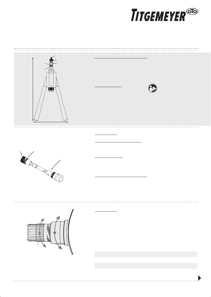
Arbeitsbereich: Blindnietmuttern M4 - M5 - M6 - M8 - M10 - M12
Werkstoff: Aluminium, Stahl und Edelstahl
Abmessung: 465 (L) x 180 (H)
Gewicht: 1,80 Kg
BESCHREIBUNG
1. Gehäuse
2. Handhebel Links und Rechts
3. Drehknopf
4. Gewindedorn M4-M12
5. Mundstück M4-M12
6. Kontermutter
7. Vordere Hülse mit Hubskala
8. Einstellmutter
BEDIENUNGSANLEITUNG
HANDNIETZANGE FÜR BLINDNIETMUTTERN M4-M12
TIOS HN12 PT
1
Handbuch TIOS HN12 PT |
B
A
56
mandrel pin
8
Manual TIOS HN12 PT |
ANWEISUNG
NACH ÖFFNEN DER BOX PRÜFEN:
Die Handnietzange wird standardmäßig mit dem Gewindedorn M12 und
Mundstück M12 vormontiert geliefert. Weitere Wechselteile sind im Karton.
ERSTE BENUTZUNG:
Vergewissern Sie sich vor dem Gebrauch der Handnietzange dass der richtige
Umrüstsatz, entsprechend der Blindnietmutter, montiert ist. Andernfalls
wechseln Sie in eine andere Abmessung.
Wechsel zu einer anderen Abmessung:
Lösen Sie die Kontermutter (6) und drehen Sie das Mundstück (5) heraus.
Drücken Sie leicht auf den Gewindedorn und ziehen dann den Pin zur
Sicherung des Gewindedornes heraus. Wählen Sie den benötigten Umrüstsatz
und montieren Sie in umgekehrter Reihenfolge den Gewindedorn und das
Mundstück.
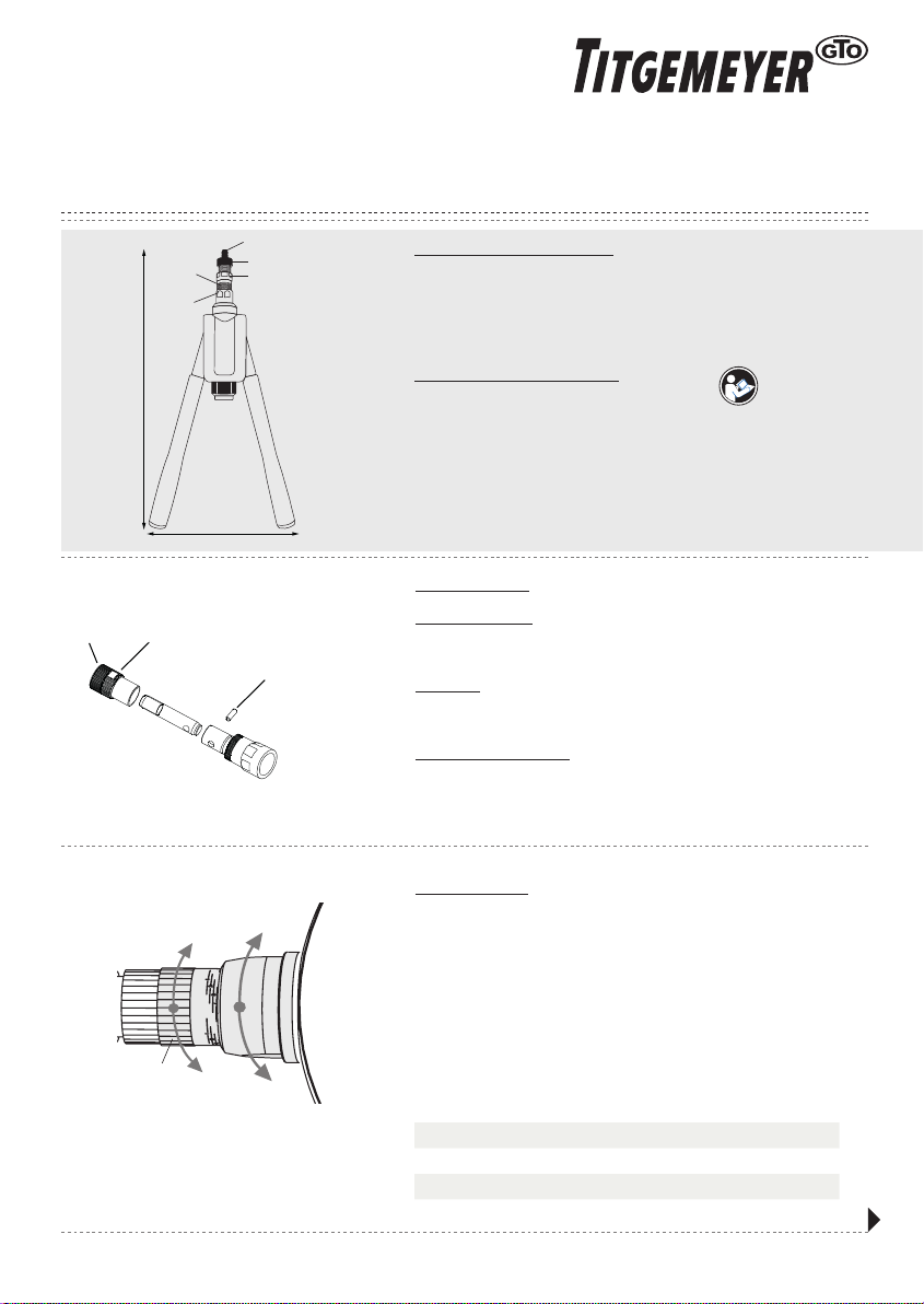
Hubeinstellung:
Schließen Sie die Hebel (2) vollständig, die Backen und Feder im inneren
Gehäuse sind nun geöffnet. Lösen Sie die Einstellmutter (8) und drehen Sie die
vordere Hülse (7) mit der Hubeinstellung nach rechts im Uhrzeigersinn um den
Hub zu reduzieren, oder nach Links, gegen den Uhrzeigersinn, um den Hub
zu erhöhen. Anhand der unten aufgeführten Tabelle können Sie Hubangaben
ablesen und entsprechend einstellen bzw. ausführen
Der korrekte Hub ist abhängig von:
• dem richtigen Klemmbereich
• entsprechend der Materialstärke
Abmessung M4 M5 M6 M8 M10 M12
Hubposition 2 2,5 3 4 5 6
Hebelbewegungen 1 1 1 - 1,5 1 - 2 2 - 3 3 - 4
H
L
5
2 2
7
8
4
6
3
1
+unlock
lock
-
7
8
Bedienungsanleitung lesen

Einstellung des Mundstücks:
Nach der Hubeinstellung ist es wichtig das Mundstück (5) einzustellen
und mit der Kontermutter (6) zu sichern. Öffnen Sie die Hebel bis zum
Anschlag, Sie hören dann ein Klickgeräusch und die Mechanik ist entriegelt.
Die Blindnietmutter auf den Gewindedorn drehen bis ein Gewindegang
des Gewindedorns am Schaftende der Blindnietmutter übersteht. Dann
das Mundstück (5) bis zum Anschlag gegen den Kopf der Blindnietmutter
drehen. Mit der Kontermutter (5) sichern. Diesen Vorgang bei jedem Wechsel
der Abmessung wiederholen.
Setzen der Blindnietmutter:
Öffnen Sie die Hebel bis zum Anschlag, Sie hören dann ein Klickgeräusch
und die Ratschenmechanik ist entriegelt. Die Blindnietmutter auf den
Gewindedorn des Werkzeuges drehen bis zum Anschlag an das Mundstück.
Die aufgeschraubte Blindnietmutter mit dem Werkzeug in das vorbereitete
Loch, entsprechend Vorgaben, stecken. Die Hebel nun schließen, die
Ratschenmechanik ist aktiv. Nun öffnen Sie die Hebel zu einem Drittel, Sie
hören das Klickgeräusch der Mechanik und schließen dann die Hebel ganz.
Dieser Schritt ist entsprechend der Hubzahl zu wiederholen. Anschließend
den Gewindedorn mittels des Drehknopfes (3) herausdrehen. Prüfen Sie den
festen Sitz der Blindnietmutter.
Wichtig: Nach dem Einstellen der Nietmutter dürfen die Hebel nicht
komplett bis zum Anschlag geöffnet werden, da ansonsten die
Ratschenmechanik ausgeschaltet ist. In diesem Fall wie oben beschrieben
vorgehen.
D
C
2
Handbuch TIOS HN12 PT | 7
Manual TIOS HN12 PT |
7
8
9
10
1 1
1 2
13
1 4
1 5 1 7 1 81 6 19
2 0
2 1
22
2 3
24
2 5
2 6
1
3
5
6
4
2
31
3 2
30
3 3
3 8
4 1
4 2
43
4 4
4 5
3 4
3 5
3 6
3 7
3 9
4 0 2 7
2 9
28
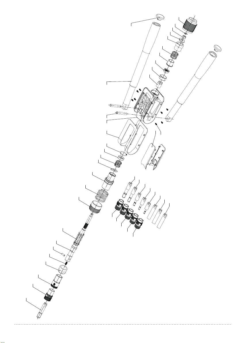
TIOS HN12 PT Die markierten Positionen sind Verschleißartikel und unterliegen nicht der Gewährleistung.
104P00950 13 04P00715 25 04P00726 37 04P00960
204A00230 14 04P00716 26 04P00727 38 04P00969
304P00958 15 04P00721 27 04P00972 39 04P00970
404P00704 16 04P00717 28 04P00541 40 04P00971
504P00807 17 04A00218 29 04F00103 41 04A00236
604P00806 18 04P00713 30 04P00904 42 04A00235
704A00231 19 04A00219 31 04F00100 43 04A00234
804P00706 20 04P00816 32 04P00720 44 04A00233
904P00705 21 04P00722 33 04P00968 45 04A00232
10 04P00707 22 04P00723 34 04P00966 47 04P00625
11 04A00217 23 04P00724 35 04P00964 48 04P00626
12 04P00714 24 04P00725 36 04P00962
6 5
click
unlock
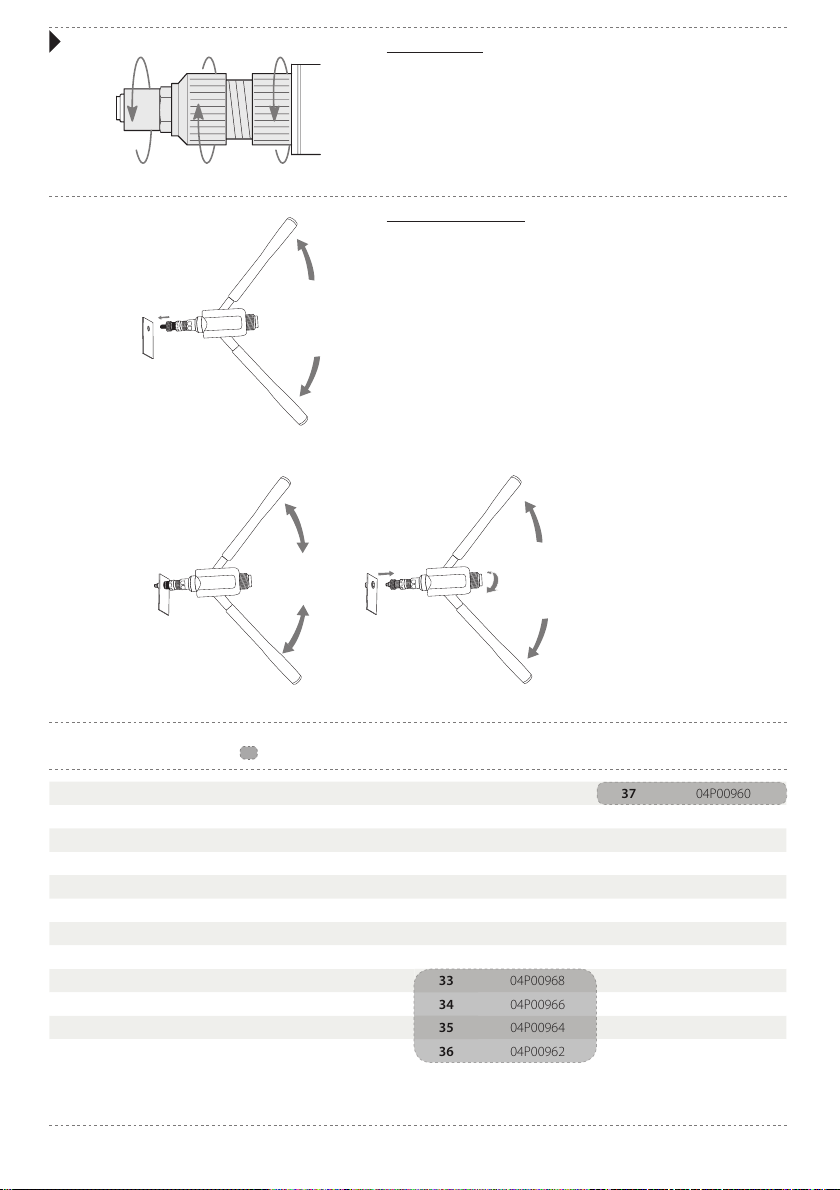
Anvil adjustment:
After adjustments to the stroke, it is necessary to adjust the anvil (5) and
its counter lock nut (6). Open the levers up to maximum, there is a clicking
sound, to extend the mandrel completely. The protrusion of the mandrel out
of the anvil must be as long as the whole rivet nut. Unscrewing the counter
lock nut (6) to adjust the anvil (5) by turning left or right, to increase or
decrease the length. After the correct length is applied, screw the counter
lock nut until it is tight. Changing the threaded inserts or stroke requires this
step every time.
Setting a threaded insert:
Put the tool in start position by opening the levers up to maximum. There
is a clicking sound. The mandrel will extend completely and the ratchet
mechanism is unlocked. Screw the insert on the threaded end of the
mandrel and insert it into the hole of the material. The hole size must
be slightly larger the rivet nut, check the drill specifications of the rivet
nut. Close the levers completely once to activate the ratchet mechanism.
Now open de levers for one third till you hear the clicking sound of the
mechanism, then close the levers completely. Repeat these steps to clamp
the rivet nut into the material tightly. After the rivet nut is set, unscrew the
threaded insert, by using the turning knob on the mandrel.
Important: after having started setting the rivet nut, do not open the levers
completely anymore before the rivet nut has been set. When levers have
been opened completely before having set the rivet nut, the ratchet process
has to be started again.
D
C
6
Manual TIOS HN12 PT | 3
Handbuch TIOS HN12 PT |
7
8
9
10
1 1
1 2
13
1 4
1 5 1 7 1 81 6 19
2 0
2 1
22
2 3
24
2 5
2 6
1
3
5
6
4
2
31
3 2
30
3 3
3 8
4 1
4 2
43
4 4
4 5
3 4
3 5
3 6
3 7
3 9
4 0 2 7
2 9
28
TIOS HN12 PT the marked items are consumables (not covered by any guarantee)
104P00950 13 04P00715 25 04P00726 37 04P00960
204A00230 14 04P00716 26 04P00727 38 04P00969
304P00958 15 04P00721 27 04P00972 39 04P00970
404P00704 16 04P00717 28 04P00541 40 04P00971
504P00807 17 04A00218 29 04F00103 41 04A00236
604P00806 18 04P00713 30 04P00904 42 04A00235
704A00231 19 04A00219 31 04F00100 43 04A00234
804P00706 20 04P00816 32 04P00720 44 04A00233
904P00705 21 04P00722 33 04P00968 45 04A00232
10 04P00707 22 04P00723 34 04P00966 47 04P00625
11 04A00217 23 04P00724 35 04P00964 48 04P00626
12 04P00714 24 04P00725 36 04P00962
6 5
click
unlock

TECHNICAL INFORMATION
Capacity: Blind rivet nuts M4 - M5 – M6 – M8 – M10 – M12
Material: Aluminium, Steel and Stainless Steel
Size: 465 (L) x 180 (H)
Weight: 1,8 Kg
DESCRIPTION OF THE TOOL
1. Tool body
2. Left and right lever
3. Turning knob
4. Mandrel M12
5. Anvil M12
6. Counter lock nut
7. Front sleeve with stroke indicator
8. Adjust nut
Read the manual
OPERATING INSTRUCTIONS
HAND TOOL FOR BLIND RIVET NUT M4-M12
TIOS HN12 PT
5
Manual TIOS HN12 PT |
B
A
56
mandrel pin
4
Handbuch TIOS HN12 PT |
INSTRUCTIONS
OPENING THE BOX:
The hand tool will be standard equipped with the M12 anvil and M12 mandrel.
The other components will be stored separate in the carton box.
FIRST USE:
Make sure before using the tool that the anvil and mandrel are suitable for the
thread of the insert to be used. Otherwise change to a different size.
Change to a different size:
Unscrew the anvil (5) and the lock nut (6). Push slightly on the mandrel, to
release the spring and take out the mandrel pin. The mandrel can now be
changed. Replace it by choosing the correct size from the spare parts in the
carton box.
Stroke adjustment:
Close the left and right lever (2) completely, in this way the jaws and internal
spring are released. Loosen the adjust nut (8) and turn the front sleeve (7) with
stroke indicator to the right (clockwise) to reduce the stroke. By reducing the
stroke, the deformation of the rivet nut will be smaller. See below overview for
the correct stroke position for each size of rivet nuts. Now screw the adjust nut
till it is tight, the stroke is adjusted.
Turn the front sleeve (7) with stroke indicator to the left (counter clockwise) to
increase the stroke. By increasing the stroke, the deformation of the rivet nut
will bigger. The correct stroke is dependent on:
• the correct griprange
• the correct blind rivet nut
Nut Size M4 M5 M6 M8 M10 M12
Stroke Position 2 2,5 3 4 5 6
Movements 1 1 1 - 1,5 1 - 2 2 - 3 3 - 4
H
L
5
2 2
7
8
4
6
3
1
+unlock
lock
-
7
8
Anvil adjustment:
After adjustments to the stroke, it is necessary to adjust the anvil (5) and
its counter lock nut (6). Open the levers up to maximum, there is a clicking
sound, to extend the mandrel completely. The protrusion of the mandrel out
of the anvil must be as long as the whole rivet nut. Unscrewing the counter
lock nut (6) to adjust the anvil (5) by turning left or right, to increase or
decrease the length. After the correct length is applied, screw the counter
lock nut until it is tight. Changing the threaded inserts or stroke requires this
step every time.
Setting a threaded insert:
Put the tool in start position by opening the levers up to maximum. There
is a clicking sound. The mandrel will extend completely and the ratchet
mechanism is unlocked. Screw the insert on the threaded end of the
mandrel and insert it into the hole of the material. The hole size must
be slightly larger the rivet nut, check the drill specifications of the rivet
nut. Close the levers completely once to activate the ratchet mechanism.
Now open de levers for one third till you hear the clicking sound of the
mechanism, then close the levers completely. Repeat these steps to clamp
the rivet nut into the material tightly. After the rivet nut is set, unscrew the
threaded insert, by using the turning knob on the mandrel.
Important: after having started setting the rivet nut, do not open the levers
completely anymore before the rivet nut has been set. When levers have
been opened completely before having set the rivet nut, the ratchet process
has to be started again.
D
C
6
Manual TIOS HN12 PT | 3
Handbuch TIOS HN12 PT |
7
8
9
10
1 1
1 2
13
1 4
1 5 1 7 1 81 6 19
2 0
2 1
22
2 3
24
2 5
2 6
1
3
5
6
4
2
31
3 2
30
3 3
3 8
4 1
4 2
43
4 4
4 5
3 4
3 5
3 6
3 7
3 9
4 0 2 7
2 9
28
TIOS HN12 PT the marked items are consumables (not covered by any guarantee)
104P00950 13 04P00715 25 04P00726 37 04P00960
204A00230 14 04P00716 26 04P00727 38 04P00969
304P00958 15 04P00721 27 04P00972 39 04P00970
404P00704 16 04P00717 28 04P00541 40 04P00971
504P00807 17 04A00218 29 04F00103 41 04A00236
604P00806 18 04P00713 30 04P00904 42 04A00235
704A00231 19 04A00219 31 04F00100 43 04A00234
804P00706 20 04P00816 32 04P00720 44 04A00233
904P00705 21 04P00722 33 04P00968 45 04A00232
10 04P00707 22 04P00723 34 04P00966 47 04P00625
11 04A00217 23 04P00724 35 04P00964 48 04P00626
12 04P00714 24 04P00725 36 04P00962
6 5
click
unlock

Einstellung des Mundstücks:
Nach der Hubeinstellung ist es wichtig das Mundstück (5) einzustellen
und mit der Kontermutter (6) zu sichern. Öffnen Sie die Hebel bis zum
Anschlag, Sie hören dann ein Klickgeräusch und die Mechanik ist entriegelt.
Die Blindnietmutter auf den Gewindedorn drehen bis ein Gewindegang
des Gewindedorns am Schaftende der Blindnietmutter übersteht. Dann
das Mundstück (5) bis zum Anschlag gegen den Kopf der Blindnietmutter
drehen. Mit der Kontermutter (5) sichern. Diesen Vorgang bei jedem Wechsel
der Abmessung wiederholen.
Setzen der Blindnietmutter:
Öffnen Sie die Hebel bis zum Anschlag, Sie hören dann ein Klickgeräusch
und die Ratschenmechanik ist entriegelt. Die Blindnietmutter auf den
Gewindedorn des Werkzeuges drehen bis zum Anschlag an das Mundstück.
Die aufgeschraubte Blindnietmutter mit dem Werkzeug in das vorbereitete
Loch, entsprechend Vorgaben, stecken. Die Hebel nun schließen, die
Ratschenmechanik ist aktiv. Nun öffnen Sie die Hebel zu einem Drittel, Sie
hören das Klickgeräusch der Mechanik und schließen dann die Hebel ganz.
Dieser Schritt ist entsprechend der Hubzahl zu wiederholen. Anschließend
den Gewindedorn mittels des Drehknopfes (3) herausdrehen. Prüfen Sie den
festen Sitz der Blindnietmutter.
Wichtig: Nach dem Einstellen der Nietmutter dürfen die Hebel nicht
komplett bis zum Anschlag geöffnet werden, da ansonsten die
Ratschenmechanik ausgeschaltet ist. In diesem Fall wie oben beschrieben
vorgehen.
D
C
2
Handbuch TIOS HN12 PT | 7
Manual TIOS HN12 PT |
7
8
9
10
1 1
1 2
13
1 4
1 5 1 7 1 81 6 19
2 0
2 1
22
2 3
24
2 5
2 6
1
3
5
6
4
2
31
3 2
30
3 3
3 8
4 1
4 2
43
4 4
4 5
3 4
3 5
3 6
3 7
3 9
4 0 2 7
2 9
28
TIOS HN12 PT Die markierten Positionen sind Verschleißartikel und unterliegen nicht der Gewährleistung.
104P00950 13 04P00715 25 04P00726 37 04P00960
204A00230 14 04P00716 26 04P00727 38 04P00969
304P00958 15 04P00721 27 04P00972 39 04P00970
404P00704 16 04P00717 28 04P00541 40 04P00971
504P00807 17 04A00218 29 04F00103 41 04A00236
604P00806 18 04P00713 30 04P00904 42 04A00235
704A00231 19 04A00219 31 04F00100 43 04A00234
804P00706 20 04P00816 32 04P00720 44 04A00233
904P00705 21 04P00722 33 04P00968 45 04A00232
10 04P00707 22 04P00723 34 04P00966 47 04P00625
11 04A00217 23 04P00724 35 04P00964 48 04P00626
12 04P00714 24 04P00725 36 04P00962
6 5
click
unlock

TECHNISCHE INFORMATIONEN
Arbeitsbereich: Blindnietmuttern M4 - M5 - M6 - M8 - M10 - M12
Werkstoff: Aluminium, Stahl und Edelstahl
Abmessung: 465 (L) x 180 (H)
Gewicht: 1,80 Kg
BESCHREIBUNG
1. Gehäuse
2. Handhebel Links und Rechts
3. Drehknopf
4. Gewindedorn M4-M12
5. Mundstück M4-M12
6. Kontermutter
7. Vordere Hülse mit Hubskala
8. Einstellmutter
BEDIENUNGSANLEITUNG
HANDNIETZANGE FÜR BLINDNIETMUTTERN M4-M12
TIOS HN12 PT
1
Handbuch TIOS HN12 PT |
B
A
56
mandrel pin
8
Manual TIOS HN12 PT |
ANWEISUNG
NACH ÖFFNEN DER BOX PRÜFEN:
Die Handnietzange wird standardmäßig mit dem Gewindedorn M12 und
Mundstück M12 vormontiert geliefert. Weitere Wechselteile sind im Karton.
ERSTE BENUTZUNG:
Vergewissern Sie sich vor dem Gebrauch der Handnietzange dass der richtige
Umrüstsatz, entsprechend der Blindnietmutter, montiert ist. Andernfalls
wechseln Sie in eine andere Abmessung.
Wechsel zu einer anderen Abmessung:
Lösen Sie die Kontermutter (6) und drehen Sie das Mundstück (5) heraus.
Drücken Sie leicht auf den Gewindedorn und ziehen dann den Pin zur
Sicherung des Gewindedornes heraus. Wählen Sie den benötigten Umrüstsatz
und montieren Sie in umgekehrter Reihenfolge den Gewindedorn und das
Mundstück.
Hubeinstellung:
Schließen Sie die Hebel (2) vollständig, die Backen und Feder im inneren
Gehäuse sind nun geöffnet. Lösen Sie die Einstellmutter (8) und drehen Sie die
vordere Hülse (7) mit der Hubeinstellung nach rechts im Uhrzeigersinn um den
Hub zu reduzieren, oder nach Links, gegen den Uhrzeigersinn, um den Hub
zu erhöhen. Anhand der unten aufgeführten Tabelle können Sie Hubangaben
ablesen und entsprechend einstellen bzw. ausführen
Der korrekte Hub ist abhängig von:
• dem richtigen Klemmbereich
• entsprechend der Materialstärke
Abmessung M4 M5 M6 M8 M10 M12
Hubposition 2 2,5 3 4 5 6
Hebelbewegungen 1 1 1 - 1,5 1 - 2 2 - 3 3 - 4
H
L
5
2 2
7
8
4
6
3
1
+unlock
lock
-
7
8
Bedienungsanleitung lesen
Table of contents
Languages:
Other Titgemeyer Rivet Tools manuals

Titgemeyer
Titgemeyer RL100-2 User manual

Titgemeyer
Titgemeyer RL50-2 User manual

Titgemeyer
Titgemeyer MS 40A User manual

Titgemeyer
Titgemeyer MS 50 User manual

Titgemeyer
Titgemeyer RL20-2 User manual

Titgemeyer
Titgemeyer RIVETEC RL 75 User manual

Titgemeyer
Titgemeyer RL75-2 User manual

Titgemeyer
Titgemeyer RL60-2 User manual

Titgemeyer
Titgemeyer RIVETEC RL 50 User manual
Popular Rivet Tools manuals by other brands


MasterFix
MasterFix EZM1000 user manual

Worcraft PROFESSIONAL
Worcraft PROFESSIONAL CRG-S20Li instruction manual

Wespro Power Tools
Wespro Power Tools BRV1875 instructions

Toparc
Toparc HR14 Translation of the original instructions

Novus
Novus N120 manual

Sunex Tools
Sunex Tools SNAPP SX0918T operating instructions