TLV COSPECT M-COS-3 User manual

172-65188M-08 (M-COS 3,16,21 Pressure Reducing Valve) 24 June 2015
Motorized Pressure Reducing Valve for Steam
COSPECT
M-COS-3 / M-COS-16 / M-COS-21
Copyright © 2015 by TLV CO., LTD.
All rights reserved
ISO 9001/ ISO 14001
Manufacturer
Kakogawa, Japan
is approved by LRQA LTD. to ISO 9001/14001

172-65188M-08 (M-COS 3,16,21 Pressure Reducing Valve) 24 Jun 2015
1
Contents
Introduction ........................................................................ 1
Safety Considerations........................................................ 2
Specifications..................................................................... 4
Acceptable Operating Range............................................. 6
Correct Usage of the M-COS Motorized Pressure
Reducing Valve.................................................................. 7
Configuration...................................................................... 9
Installation........................................................................ 11
Controller Operation......................................................... 18
Maintenance..................................................................... 21
Disassembly..................................................................... 22
Reassembly ..................................................................... 31
Troubleshooting ............................................................... 32
Product Warranty ............................................................. 35
Introduction
Thank you for purchasing the M-COS motorized pressure reducing
valve for steam.
This product has been thoroughly inspected before being shipped from the
factory. When the product is delivered, before doing anything else, check the
specifications and external appearance to make sure nothing is out of the
ordinary. Also be sure to read this manual carefully before use and follow the
instructions to be sure of using the product properly.
The motorized pressure reducing valve for steam, model M-COS is a
high performance motor actuated remote type pressure reducing valve
adding a remote control function to the COS pressure reducing valve. It
can be easily adjusted by remote to supply dry saturated steam to the
process at the set pressure as needed without fluctuation, thus improving
steam use and contributing to the improvement of energy effeciency,
productivity and product quality..
If detailed instructions for special order specifications or options not
contained in this manual are required, please contact for full details.
This instruction manual is intended for use with the model(s) listed on the
front cover. It is needed not only for installation, but also for subsequent
maintenance, disassembly/reassembly and troubleshooting. Please keep it in
a safe place for future reference.
172-65188M-08 (M-COS 3,16,21 Pressure Reducing Valve) 24 Jun 2015
2
Safety Considerations
•Read this section carefully before use and be sure to follow the instructions.
•Installation, inspection, maintenance, repairs, disassembly, adjustment and valve
opening/closing should be carried out only by trained maintenance personnel.
•The precautions listed in this manual are designed to ensure safety and prevent
equipment damage and personal injury. For situations that may occur as a result
of erroneous handling, three different types of cautionary items are used to
indicate the degree of urgency and the scale of potential damage and danger:
DANGER, WARNING and CAUTION.
•The three types of cautionary items above are very important for safety: be sure
to observe all of them as they relate to installation, use, maintenance, and repair.
Furthermore, TLV accepts no responsibility for any accidents or damage
occurring as a result of failure to observe these precautions.
Symbols
Indicates a DANGER, WARNING or CAUTION item.
DANGER
Indicates an urgent situation which poses a threat of death or
serious injury
WARNING
Indicates that there is a potential threat of death or serious injury
CAUTION
Indicates that there is a possibility of injury or equipment /
product damage
WARNING
NEVER apply direct heat to the float.
The float may explode due to increased internal pressure, causing
accidents leading to serious injury or damage to property and
equipment.
CAUTION
Install properly and DO NOT use this product outside the
recommended operating pressure, temperature and other
specification ranges.
Improper use may result in such hazards as damage to the
product or malfunctions that may lead to serious accidents. Local
regulations may restrict the use of this product to below the
conditions quoted.
DO NOT use the product in excess of the maximum operating
pressure differential.
Such use could make discharge through the steam trap impossible
(blocked).
Use hoisting equipment for heavy objects (weighing
approximately 20 kg or more).
Failure to do so may result in back strain or other injury if the
object should fall.
Safety considerations are continued on the next page.
172-65188M-08 (M-COS 3,16,21 Pressure Reducing Valve) 24 Jun 2015
3
CAUTION
Take measures to prevent people from coming into direct
contact with product outlets.
Failure to do so may result in burns or other injury from the
discharge of fluids.
When disassembling or removing the product, wait until the
internal pressure equals atmospheric pressure and the
surface of the product has cooled to room temperature.
Disassembling or removing the product when it is hot or under
pressure may lead to discharge of fluids, causing burns, other
injuries or damage.
Be sure to use only the recommended components when
repairing the product, and NEVER attempt to modify the
product in any way.
Failure to observe these precautions may result in damage to the
product and burns or other injury due to malfunction or the
discharge of fluids.
Do not use excessive force when connecting threaded pipes
to the product.
Over-tightening may cause breakage leading to fluid discharge,
which may cause burns or other injury.
Use only under conditions in which no freeze-up will occur.
Freezing may damage the product, leading to fluid discharge,
which may cause burns or other injury.
Use only under conditions in which no water hammer will
occur.
The impact of water hammer may damage the product, leading
to fluid discharge, which may cause burns or other injury.
Make sure the power supply switch is OFF before carrying
out work on the wiring or inspections involving disassembly.
If such work is carried out with the power on, there is a danger
that equipment may malfunction or electric shock may occur,
leading to injury or other accidents.
Make sure that wiring work requiring a special license is
carried out by qualified personnel.
If carried out by unqualified personnel, overheating or short circuits
leading to injury, fires, damage or other accidents may occur.
When using this product, NEVER stand close to, or leave
tools anywhere near moving parts, such as the shaft.
Contact with moving parts or objects becoming caught in moving
parts could lead to injury, damage or other accidents.
172-65188M-08 (M-COS 3,16,21 Pressure Reducing Valve) 24 Jun 2015
4
Specifications
Install properly and DO NOT use this product outside the recommended
operating pressure, temperature and other specification ranges.
Improper use may result in such hazards as damage to the product or
malfunctions which may lead to serious accidents. Local regulations
may restrict the use of this product to below the conditions quoted.
CAUTION
DO NOT use the product in excess of the maximum operating pressure
differential; such use could make discharge impossible (blocked).
CAUTION
Use only under conditions in which no freeze-up will occur. Freezing
may damage the product, leading to fluid discharge, which may cause
burns or other injury.
CAUTION
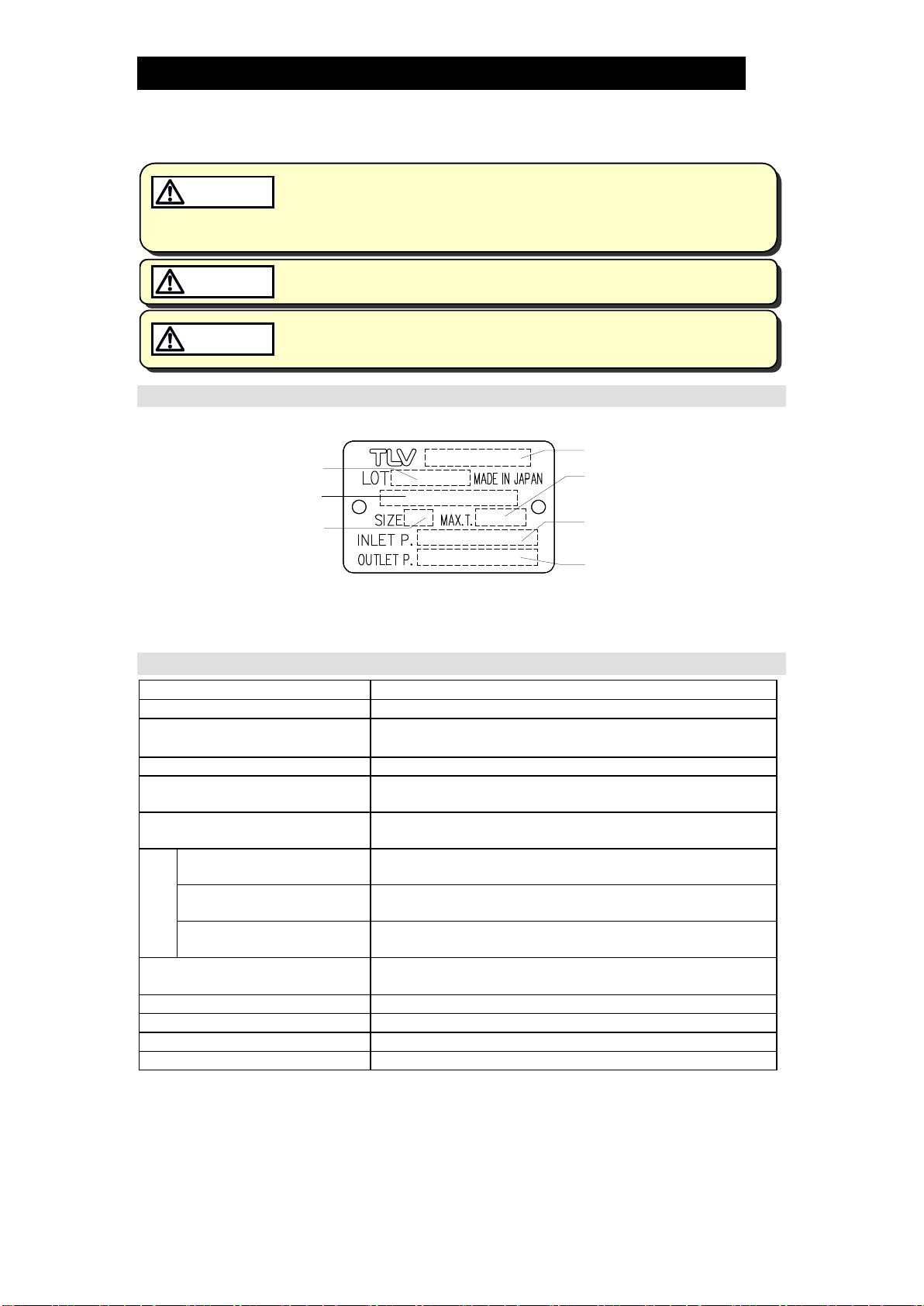
Valve
Refer to the product nameplate for detailed specifications.
Model
Nominal Diameter
Maximum Operating
Temperature
Valve No.*
Secondary Pressure
Adjustable Range
Primary Pressure
Range
Production Lot No.
* Valve No. is displayed for products with options. This item is omitted from the nameplate
when there are no options.
Actuator
Model
M-COS-3 / M-COS-16 /M-COS-21
Drive System
ON/OFF control of reversible motor
Line Voltage
100/110 VAC
±
10% or 200/220 VAC
±
10% (50/60 H
Z
)
(Supplied from controller) (Single phase)
Power Consumption
Included in Controller
Withstand Voltage
Between power terminal and ground terminal:
1800 VAC (60 HZ) for 1 second
Insulation Resistance
Between power terminal and ground terminal:
Min. 100 MΩ(500 VDC)
Operating
Conditions
Ambient Temperature 0 – 60 °C
Water Resistance
JIS Rain-proof type
(Motor must not come into contact with dew)
Vibration Resistance Max. 0.5 G
Cable Heat Resistance
70 °C
(Cable must not come into contact directly with steam piping)
Thermal Protection
Motor with built-in 120 ºC thermal protector
Open/Close Time
Approx. 40 seconds
Continual Actuator Operation
Approx. 5 minutes maximum
Manual Operation
Possible

172-65188M-08 (M-COS 3,16,21 Pressure Reducing Valve) 24 Jun 2015
5
Controller
Model
MC-2
Pressure Display Function
Yes
(select between displays of measured pressure and
upper pressure)
Pressure Upper Limit Setting
Function
Setting is possible
Power Source Voltage
100/110 VAC
±
10% or 200/220 VAC
±
10% (50/60 HZ)
Power
Consumption
While motor is
stopped
7 VA
While motor is
in operation
(TYP.) 65 VA (MAX.) 75 VA
Withstand Voltage
Between power terminal and ground terminal:
1800 VAC (60 HZ) for 1 second
Insulation Resistance
Between ground terminal and each terminal:
Min. 100 MΩ(500 VDC)
Operating
Conditions
Ambient Temperature 0 –50 °C
Ambient Humidity 5 –90% RH (without dew, indoor use)
Vibration Resistance Max. 0.5 G
Dimensions (Unit: mm)
93 (W) ×184 (H) ×73 (D)
Weight
1.1 kg
Installation
Wall mounting (M5 screw x 4)
Material/Coating
Steel plate/black melamine
Pressure
Indication
Indication Range
0 –1999 kPaG
Indication Accuracy
±
0.5%F.S.
Pressure Sensor
Standard type
Allowable Pressure
Setting Range
0 – 1999 kPaG
Pressure Sensor
Standard type
Model
M-COS-3 M-COS-16
/
M-COS-21
Pressure Measurement Range
0– 0.5 MPaG (500 kPaG) type
0 – 2.0 MPaG type
0–0.5MPaG (500kPaG) type
*1
Signal Output
4 – 20 mADC (load resistance 250 Ω/15 VDC)
Measurement Accuracy
±
0.3%F.S.
Temperature Drift
±
0.02%F.S/°C
Maximum Allowable Pressure
2 times the maximum value of the measurement range
Ambient Temperature
−40 – +85 °C (Sensor must not come into contact with dew)
Water Resistance
JIS Rain-proof type
Material for Wetted Parts
AISI 316 / DIN W. No. 1.4401
Connection Thread
G(PF) 3/8
Weight
Approx. 400 g
Accessories
Siphon Tube
(connector screw for piping installation end: R(PT)
3
/8)
*1When the secondary pressure is 0.03 MPaG or less, choose a 0 –0.5 MPaG (500 kPaG)
type sensor

172-65188M-08 (M-COS 3,16,21 Pressure Reducing Valve) 24 Jun 2015
6
Acceptable Operating Range
Model
M-COS-3
M-COS-16
M-COS-21
Primary Pressure Range
0.1 – 0.3 MPaG
0.2 – 1.6 MPaG
1.35 – 2.1 MPaG
Secondary Pressure
Adjustable Pressure
Range
(All conditions must be
met)
0.01 – 0.05 MPaG
Within 10 –84% of the primary pressure
Minimum adjustable
pressure of 0.03 MPaG
Minimum adjustable
pressure of 0.55 MPaG
Pressure differential
between 0.07 – 0.85
MPa
Maximum pressure
differential of 0.85 MPa
Minimum Adjustable
Flow Rate
5% of rated flow
rate
5% of rated flow rate; 10% of rated flow rate for
sizes 65 mm – 100 mm
172-65188M-08 (M-COS 3,16,21 Pressure Reducing Valve) 24 Jun 2015
7
Correct Usage of the
M-COS
Motorized Pressure
Reducing Valve
Install properly and DO NOT use this product outside the recommended
operating pressure, temperature and other specification ranges.
Improper use may result in such hazards as damage to the product or
malfunctions which may lead to serious accidents. Local regulations
may restrict the use of this product to below the conditions quoted.
CAUTION
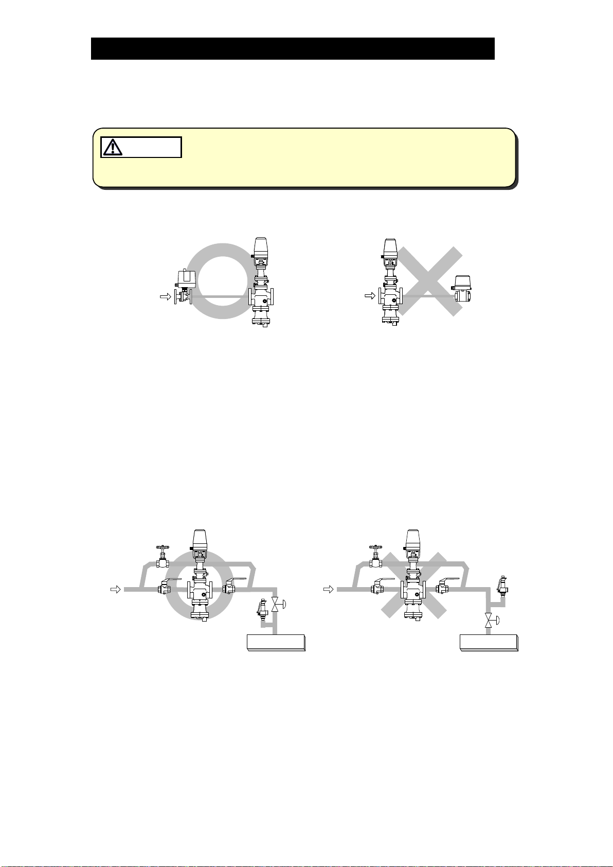
1.
The M-COS should be operated only within its specifications.
2.
Installing an ON/OFF Valve (Solenoid Valve or Motorized Valve)
M-COS
Motorized
Valve
Inlet side
Outlet side
Solenoid
Valve
Outlet side
Solenoid
Valve
M-COS
If an on-off valve, such as a motorized valve, is required to stop supply of steam to
the steam-using equipment, install it at the inlet side of the M-COS. If a solenoid
valve is installed at the outlet of the M-COS, its opening and closing will cause heavy
chattering and may lead to damage of the piston and main valve. (When the on-off
valve opens, the secondary pressure of the M-COS changes from zero to the set
pressure. Passing through an area of the reducing ratio of less than 10:1, where
adjustment is impossible, chattering occurs momentarily. To save energy, it is
recommended to install the on-off valve as near to the boiler as possible.
NOTE: To prevent water hammer, it is recommended that a slow-acting motorized
on-off valve be used. In particular, if a fast-acting on-off solenoid valve is
used for frequent temperature control, the potential water hammer effect
can damage the steam-using equipment and the M-COS.
3.
Installing a Control Valve
M-COS
Safety
Valve
Control
Valve
Steam-using
Equipment
Safety
Valve
Control
Valve
M-COS
Steam-using
Equipment
A control valve installed between the M-COS and the steam-using equipment
(downstream of the M-COS) for controlling equipment temperature may raise the
pressure between the M-COS and the control valve when the control valve is
closed, depending on the spatial relationship. A safety valve should be installed
downstream of the control valve.
NOTE: When installing a safety valve to protect the steam-using equipment, be
sure to install it on the steam-using equipment or directly before the inlet
of the steam-using equipment. If the safety valve is installed on the
outlet side of the M-COS between the M-COS and a control valve, an
eventual pressure rise could activate the safety valve.

172-65188M-08 (M-COS 3,16,21 Pressure Reducing Valve) 24 Jun 2015
8
4.
Precautions for the Installation of Additional Fittings Before or After the M-COS
In order to ensure stable steam flow, the piping upstream and downstream of
the M-COS must be straight runs. If a M-COS is installed either directly before or
after an elbow or control valve, unevenness in steam flow may result in
chattering and unstable pressure.
To ensure stable steam flow, it is recommended that the M-COS be installed on
straight runs of piping, as illustrated below. (d = pipe diameter)
(1) Inlet (primary side) of the M-COS
Maintain a straight piping
run of 10 d or more when a
manual valve, a strainer or
an elbow, etc. is installed.
(Example: if nominal size is 25
mm, have 250 mm or more)
M-COS
10 d or more
Less
than
10d
M-COS
Maintain a straight piping
run of 30 d or more when
an automated valve (on-off
valve) is installed.
(Example: if nominal size is 25
mm, have 750 mm or more)
30 d or more
M-COS
Automatic
Valve
Automatic
Valve
Less than
30 d
M-COS
(2) Outlet (secondary side) of the M-COS
Maintain a straight piping
run of 15 d or more when a
manual valve, a strainer or
an elbow, etc. is installed.
(Example: if nominal size is 25
mm, have 375 mm or more)
M-COS
15 d or more
Less
than
15 d
M-COS
Maintain a straight piping
run of 30 d or more when a
safety valve is installed.
(Example: if nominal size is 25
mm, have 750 mm or more)
M-COS
30 d or more
Safety Valve
Less than
30 d
Safety Valve
M-COS
Maintain a straight piping
run of 30 d or more when
another pressure reducing
valve is installed. (Two-
stage pressure reduction)
(Example: if nominal size is 25
mm, have 750 mm or more)
30 d or more
M-COS M-COS
Less than
30 d
M-COS M-COS
Maintain a straight piping
run of 30 d or more when a
control valve or an
automated valve (on-off
valve) is installed.
(Example: if nominal size is 25
mm, have 750 mm or more)
Control Valve
or
Automatic Valve
M-COS
30 d or more
Less than
30 d
M-COS Control Valve
or
Automatic Valve

172-65188M-08 (M-COS 3,16,21 Pressure Reducing Valve) 24 Jun 2015
9
Configuration
15 – 50 mm
Plug (option)
No.
Name
1
Main Body
2
Trap Body
3
Trap Cover
4
Separator
5
Float
6
Float Cover
7
Trap Valve Seat
8
Separator Screen
9
Main Valve Seat
10
Main Valve
11
Main Valve Holder
12
Piston
13
Cylinder
14
Pilot Screen
15
Pilot Screen Holder
16
Pilot Body
17
Pilot Valve
18
Pilot Valve Seat
19
Diaphragm
20
Diaphragm Support
21
Spring Housing
22
Coil Spring
23
Adjustment Screw
24
Adjustment Screw Guide
25
Plug – Sensing Line Port
26
Mounting Plate
27
Insulation Plate
28
Splined Shaft
29
Sleeve
30
Motor Cover
31
Motor Unit (Actuator)

172-65188M-08 (M-COS 3,16,21 Pressure Reducing Valve) 24 Jun 2015
10
65 – 100 mm
Plug (Option)
No.
Name
1
Main Body
2
Trap Body
3
Trap Cover
4
Separator
5
Float
6
Float Cover
7
Trap Valve Seat
8
Separator Screen
9
Main Valve Seat
10
Main Valve
11
Main Valve Holder
12
Piston
13
Cylinder
14
Pilot Screen
15
Pilot Screen Holder
16
Pilot Body
17
Pilot Cover
18
Pilot Valve
19
Pilot Valve Seat
20
Diaphragm
21
Diaphragm Support
22
Spring Housing
23
Coil Spring
24
Adjustment Screw
25
Adjustment Screw Guide
26
Plug – Sensing Line Port
27
Mounting Plate
28
Insulation Plate
29
Splined Shaft
30
Sleeve
31
Motor Cover
32
Motor Unit (Actuator)
33
Silencer
172-65188M-08 (M-COS 3,16,21 Pressure Reducing Valve) 24 Jun 2015
11
Installation
Install properly and DO NOT use this product outside the recommended
operating pressure, temperature and other specification ranges.
Improper use may result in such hazards as damage to the product or
malfunctions which may lead to serious accidents. Local regulations
may restrict the use of this product to below the conditions quoted.
CAUTION
Use hoisting equipment for heavy objects (weighing approximately
20 kg or more). Failure to do so may result in back strain or other injury if
the object should fall.
CAUTION
Take measures to prevent people from coming into direct contact with
product outlets. Failure to do so may result in burns or other injury from
the discharge of fluids.
CAUTION
Make sure the power supply switch is OFF before carrying out work on
the wiring or inspections involving disassembly.
If such work is carried out with the power on, there is a danger that
equipment may malfunction or electric shock may occur, leading to
injury or other accidents.
CAUTION
Make sure that wiring work requiring a special license is carried out by
qualified personnel.
If carried out by unqualified personnel, overheating or short circuits
leading to injury, fires, damage or other accidents may occur.
CAUTION
When using this product, NEVER stand close to, or leave tools anywhere
near moving parts, such as the shaft.
Contact with moving parts or objects becoming caught in moving parts
could lead to injury, damage or other accidents.
CAUTION
Installation, inspection, maintenance, repairs, disassembly, adjustment and valve
opening/closing should be carried out only by trained maintenance personnel.
1.
Blowdown
Before installing the
M-COS
, be
sure to blow down all piping
thoroughly. If this is not possible,
perform a blowdown using the
bypass valve.
Blowdown
is especially important
for newly installed piping or after
the system has been shut down
for a long period of time.
Open
Closed Closed
Blowdown using bypass valve
M-COS
2.
Removing Seal and Cap
Before installation, be sure to remove all protective
seals and caps.
(Found in 3 locations, on the product inlet and outlets.)
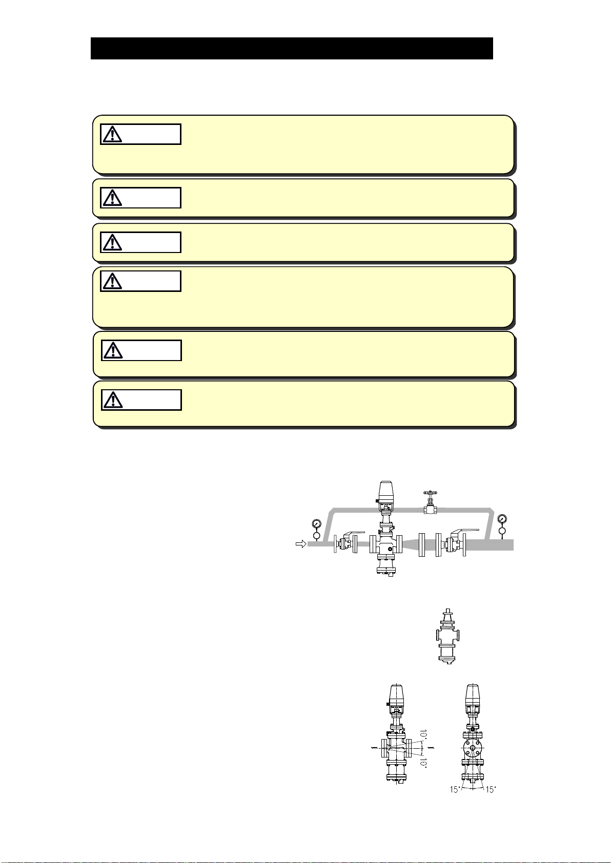
3.
Installation Angle
Install the
M-COS
vertically, so that the
arrow mark on the body points horizontally
in the direction of steam flow.
Allowable inclination is 10 degrees in the
fore-aft direction and 15 degrees in the
plane perpendicular to the steam flow line.
172-65188M-08 (M-COS 3,16,21 Pressure Reducing Valve) 24 Jun 2015
12
4.
Spacer Installation
If spacing adjustment is
necessary to accommodate
installation, install a spacer on
the outlet flange. The spacer
should consist of a spacer,
gaskets, bolts and nuts. Fit
gaskets to both sides of the
spacer between the M-COS
outlet and the pipe flange.
Fasten with bolts and nuts.
Correct spacer
location
Correct spacer
location
5.
Piping Support
Install the M-COS, paying
attention to avoid excessive
load, bending and vibration.
Support the inlet and outlet
pipes securely.
6.
Maintenance Space
150
100 100
100 400 400
Approx.
300
Leave sufficient space for
maintenance, inspection and repair.
(Unit: mm)
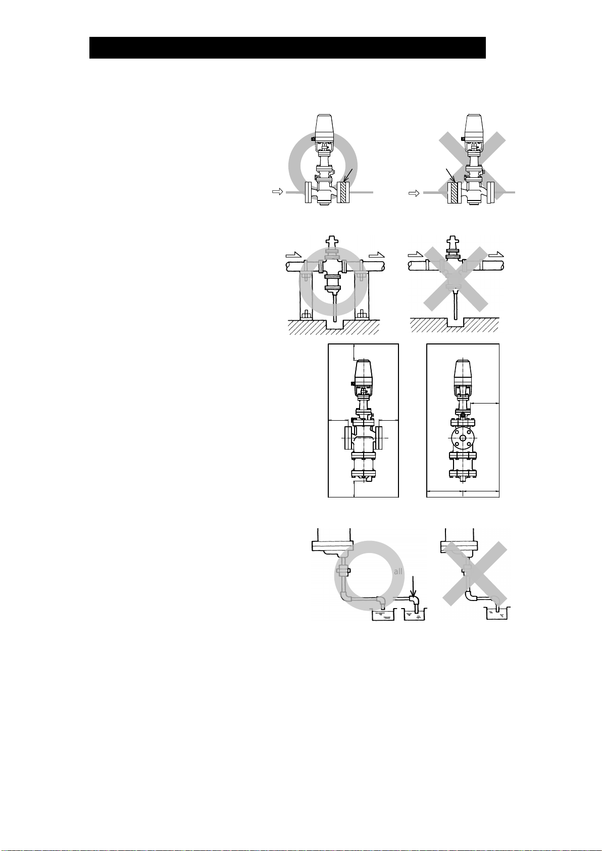
7.
Trap Outlet Piping
For ease of maintenance, installation
of a union connection is
recommended for the trap outlet pipe.
Connect the outlet pipe to a
condensate return line, or extend it to
a trench. In the case of the latter,
make sure the end of the pipe is
above the waterline.
(Dirt and water may otherwise be
sucked up by the vacuum formed
during trap closure and system
shutdown.)
Small hole

172-65188M-08 (M-COS 3,16,21 Pressure Reducing Valve) 24 Jun 2015
13
8.
Blowdown Valve (requires optional plug)
Remove the 10 mm
(3/8 in) plug (optional)
and install the
blowdown valve
In an environment of heavy dirt or scale, or when the
steam-using equipment is used only periodically,
such as for room heating equipment be sure to use
a blowdown valve.
1. Remove the plug from the main body.
2. Install the blowdown valve.
3. Open the blowdown valve (while M-COS is pressurized) and blow any
residual dirt and scale off the separator screen.
4. Periodically activate the blowdown valve to keep the system free of dirt and
scale.
9.
Piping Size/Diffuser
If it is expected that the
secondary steam flow velocity
will be more than 30 m/s, install
a diffuser in order to keep the
flow velocity below 30 m/s. If the
distance between the M-COS
and the steam-using equipment
is great, a possible drop in
pressure should be taken into
consideration when selecting the
piping size.
Straight-run Piping Lengths:
Upstream = 10 d or more; Downstream = 15 d or more
Diffuser
M-COS
(d = pipe diameter)
M-COS
10.
Two-stage Pressure Reduction
Two-stage pressure reduction should be performed whenever the pressure cannot
be reduced to the desired level with a single M-COS due to operating range
limitations, such as when the reduction ratio is greater than 10:1.
M-COS
Pressure
Gauge
Bypass
Valve
Inlet
Valve Outlet
Valve Outlet
Valve
Safety Valve
(Relief Valve)
Inlet Outlet
Bypass
Valve
Inlet
Valve
M-COS
Pressure
Gauge
Inlet
Pressure
Gauge Pressure
Gauge
Inlet
Valve Outlet
Valve
Safety Valve
(Relief Valve)
Outlet
Bypass
Valve
M-COS

172-65188M-08 (M-COS 3,16,21 Pressure Reducing Valve) 24 Jun 2015
14
11.
Accessories
Always install a shut-off valve, pressure gauge and bypass lines at both inlet
and outlet.
Ball valves, which will not retain condensate, are recommended for inlet and
outlet shut-off valves. The bypass pipe should be at least 1/2of the size of the
inlet (primary side) pipe.
M-COS has a built-in strainer, however in case an external strainer is installed,
it should be installed ahead of M-COS and the strainer should be installed
horizontally with the basket at the 3 or 9 o’clock position in order to prevent
condensate accumulation.
Ball Valve
Ball Valve
Glove Valve
M-COS
Pressure
Gauge
Pressure
Gauge
M-COS
12.
Installation of the Controller Unit
Mount the controller unit securely on a wall, etc. with self-tapping screws
inserted in the holes.
The controller is not waterproof. Be sure to install it indoors in a suitable
protected area.
The ambient temperature range specified for the normal operation of the unit is
between 0 and 50 °C. Avoid operation beyond this specified range.
Install the controller unit in a suitable place with low humidity and vibration.
13.
Installation of the Pressure Sensor
Install the pressure sensor on or near the steam using equipment on the piping.
Arrange the piping as perpendicularly as practical with the siphon tube
supplied. (Direct mounting of the sensor to the equipment or to the piping may
result in damage to the pressure sensor due to conduction of heat.)
NOTE: The pressure sensor is made to withstand a maximum pressure of
2 times the maximum value of the measurement range.
If there is a possibility that excessive pressure beyond this limit will be
applied to the sensor due to water hammer or otherwise, consult our sales
staff before continuing the installation.

172-65188M-08 (M-COS 3,16,21 Pressure Reducing Valve) 24 Jun 2015
15
14. External secondary pressure-sensing line (when required)
North American Models are factory prepared for external sensing.
An external sensing line MUST be installed.
DO NOT SUPPLY STEAM until all piping and a 10 mm secondary pressure
sensing line with a slightly falling pitch have been properly installed. Install a
shutoff valve in the pressure sensing line for maintenance purposes.
Keep the shutoff valve open at all times during operation. If the shutoff
valve is closed, M-COS will fully open and PRIMARY PRESSURE WILL BE
SUPPLIED TO THE EQUIPMENT (see “Piping Example” on next page).
CAUTION
Non-North American Models:
Factory-standard M-COS employs an internal secondary pressure-sensing
channel built into the body, saving the need to install an external pressure-
sensing line to detect the secondary pressure.
Installation of an external secondary pressure-sensing line involves closing the
internal pressure-sensing channel and installing a line from the sensing line port
to the point where pressure should be controlled. This can increase stability of
pressure control where steam loss in secondary piping and flow rate fluctuation is
high. In addition, the rated flow rate will be greater than an internal pressure-
sensing channel under the operational pressure reduction ratio of 2:1 or more.
Installation procedure
1) Loosen and remove the bolts that attach the pilot body to the main body (15 –
50 mm) or the pilot cover (65 – 100 mm) and remove the pilot body.
2) Install the blind pin (optional) by first removing the connecting tube from the
main body or pilot cover and then substituting the blind pin.
3) Re-install the pilot body and fasten the bolts evenly to the proper torque.
4) Remove the plug and connect the secondary pressure sensing line.
5) Install the secondary pressure sensing line with a slightly falling pitch. The
end of the secondary pressure sensing line should be connected to the place
on the main piping where the pressure is to be sensed (see the piping
example on next page). A shut-off valve and union should be installed in the
secondary pressure sensing line.
Main Body
Pilot Body
Secondary Pressure
Sensing Line Port
(Rc(PT)3/8, BSP3/8or NPT3/8)
Bolt
Secondary Pressure
Sensing Port
Connecting Tube
Replace the factory-
installed connecting tube
with the blind pin shipped
with the M-COS.Connecting
Tube Blind Pin
Pilot Body
15 –50 mm 65 –100 mm
172-65188M-08 (M-COS 3,16,21 Pressure Reducing Valve) 24 Jun 2015
16
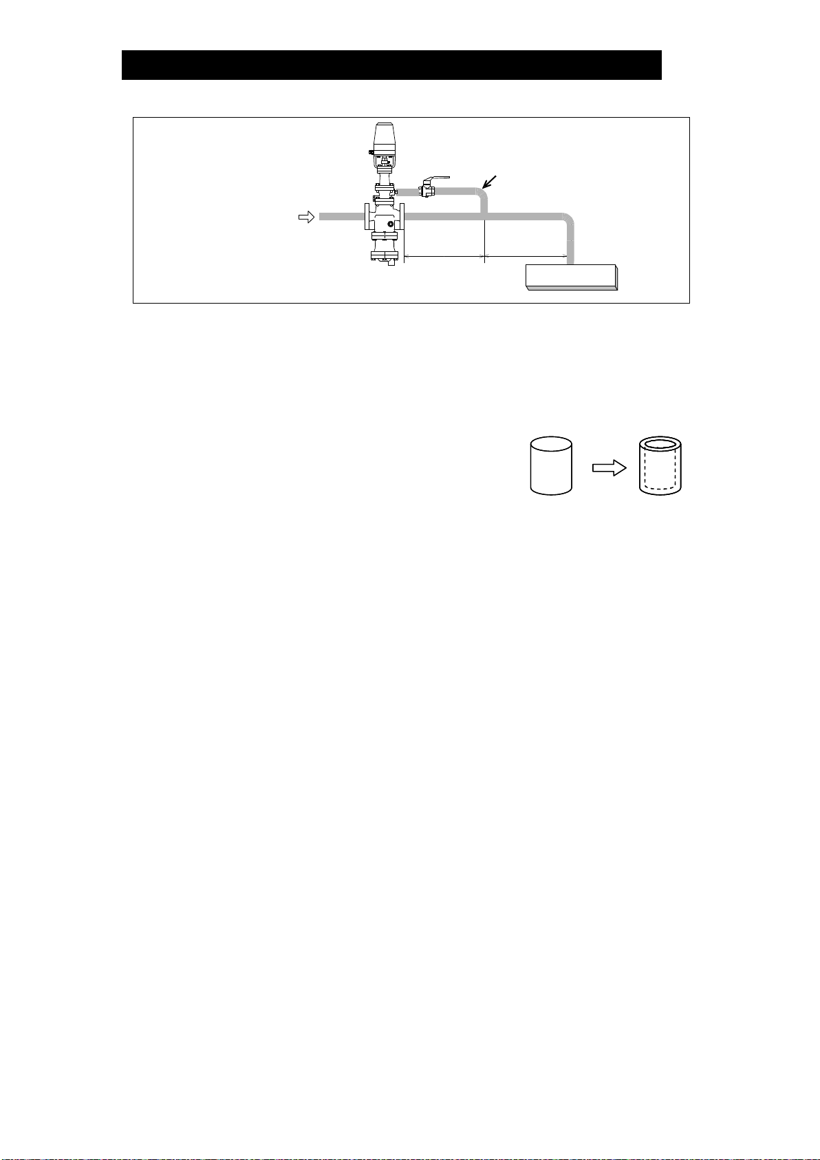
Piping example::
10 mm Pressure Sensing Line
(with a slightly falling pitch towards
the sensing point)
M-COS
1 m or 15 d,
whichever is
larger
Valve
15 d or more
Steam-using
Equipment
d = pipe diameter
15. Internal sensing for North American models
All models except North American models are factory prepared for internal sensing.
When internal pressure sensing is required for North American models, please
contact the nearest TLV representative to request both a connecting tube, which
must be installed in place of the blind pin, and a threaded secondary pressure
sensing plug.* Follow the connecting tube installation procedure shown below:
1) Loosen and remove the four (4) bolts that attach the
pilot body to the main body (15 – 50 mm) or the pilot
cover (65 – 100 mm), and remove the pilot body.
2) Install the connecting tube by first removing the
blind pin from the secondary side of the main body
or pilot cover and then substituting the connecting tube.
3) Re-install the pilot body and fasten the four (4) bolts evenly.
Consult page 31 in this manual for torque requirements of these bolts.
4) If a secondary pressure sensing pipe has previously been installed, remove it and
be certain to install the threaded secondary pressure sensing line plug in its place.
*Internal sensing should not be used when 15 mm and 20 mm M-COS-16 will be
used below 0.3 MPaG and 0.1 MPaG respectively, and below 50% of primary
pressure.
Blind Pin Connecting Tube

172-65188M-08 (M-COS 3,16,21 Pressure Reducing Valve) 24 Jun 2015
17
Wiring
MC-2
Ground
Power
Supply Motor
Pressure
Sensor
AC100V
or
AC200V
Red Black White
1 2 3 4 5 6 7 8
Class 3
Grounding
Class 3
Grounding
Red White Shield*
(+) (–)
1. Before arranging wiring, check the correct supply voltage values specified for the
controller unit and for the actuator (motor) once again.
2. Connections of the wires to the terminal board must be made securely with
insulated pressure-connection terminals.
3. To ensure safety, be sure to ground the controller unit and the actuator.
Grounding requirements: Class 3 grounding or better
(Use mild steel wires of 2 mm2 (AWG 14) or larger size and of 100 Ωor less
resistance, extending up to 20 m.)
4. Wiring should be routed in the shortest distance practical, located at least 0.5 m
away from other pieces of equipment that can be noise-generating sources.
Wiring should never contact any exposed steam piping.
Cables used for wiring shall be as follows:
Power Cable
:
min. 0.5 mm2(AWG 20) x 2-core
Motor Cable
:
min. 0.5 mm2(AWG 20) x 3-core
Pressure Sensor
:
min. 0.5 mm2(AWG 20) x 2-core shielded wire
NOTE: Wiring for the shielded wire should be made only on the controller side
and not on the pressure sensor side.
(Shielded wire should never contact the pressure sensor case.)
5. To allow access for maintenance, provide 100 mm of clearance around the
actuator when arranging wiring.
6. Upon completion of wiring to the terminal board, fit the supplied insulation board
and fix it in securely in place.
* Wiring for the pressure
switch should be made
only when necessary.

172-65188M-08 (M-COS 3,16,21 Pressure Reducing Valve) 24 Jun 2015
18
Controller Operation
<MC-2>
(7) Maximum Allowable Pressure Setting Knob
(4) Maximum Allowable Pressure LED
(2) Pressure Setting Lever Switch
(3) Pressure Lock Switch
(1) Power Switch
(1) Power Supply LED
(5) Pressure Indicator
(6) Selector Switch
Part Names and Features
NOTE: Pressure values in parentheses ( ) are for the 500 kPa (0.5 MPaG) model.
(1) Power Switch/Power Supply LED
This is the main switch for the entire controller unit. By turning ON the power
switch, the power supply LED is lit to indicate that power is supplied to the unit.
(2) Pressure Setting Lever Switch
This switch is used for adjusting steam pressure. By pushing the lever switch
toward the UP side, the pressure-adjustment screw in the M-COS unit is pushed
in (rotates clockwise from top-down view), causing the secondary pressure to rise.
Conversely, by pushing it toward the DOWN side, the pressure-adjustment screw
is pulled back (rotates counterclockwise from top-down view) causing the
pressure to fall. (By releasing your hand, the switch returns to the OFF condition.)
NOTE: Do not operate the lever switch continuously for more than 5 minutes.
If the motor is run beyond that limit, the thermal protector for the motor is
activated to bring the motor to a standstill. (Motor condition is restored to
normal when the motor has cooled.)
(3) Pressure Lock Switch
When the pressure lock switch is turned to “LOCK ON”, the pressure setting lever
switch becomes inoperative.
When the “set pressure” valve is to be fixed at a certain level, turn this switch ON.
Then, even if the set pressure lever switch is operated by mistake, the set value
will not change. (Turn the pressure lock switch OFF if it is desired to change the
set value.)
(4) Maximum Allowable Pressure LED
The LED lights up when the maximum allowable pressure switch is activated.
Once the pressure switch LED is ON, the UP side of the pressure setting lever
switch becomes inoperative, thereby disabling setting of pressures higher than
that which has been set on the pressure switch.
(If it is desired to set the upper limit pressure for the protection of the steam-
using equipment, connect a suitable pressure switch externally.)

172-65188M-08 (M-COS 3,16,21 Pressure Reducing Valve) 24 Jun 2015
19
(5) Pressure Indicator
LED in the pressure indicator window light up when the power switch (1) is turned
ON indicating either the measured pressure or the maximum allowable pressure,
depending on the setting on the selector switch (6).
Values available for indication are between 000 to 1999 kPa (500 kPa).
Pressure indicator shows about -500 (-125) on the measured pressure side
when the pressure sensor is not connected. When the measured pressure
exceeds 1999 kPa, the display shows 1∗∗∗.
(6) Selector Switch
This switch is used for selecting the desired pressure indication item (5).
Indication of measured pressure values is selected by pushing the switch upward,
and the maximum allowable pressure is selected when it is pushed downward.
Normally the selector switch is set at the measured pressure indication side.
(7) Maximum Allowable Pressure Setting Knob
This knob is used to set the maximum allowable pressure to protect the steam-
using equipment against damage. By setting the selector switch (6) at the
maximum allowable pressure, the set maximum allowable pressure is indicated.
The maximum allowable pressure setting is increased by turning the knob
clockwise, and it is decreased by turning it counterclockwise.
Setting for the maximum allowable pressure is possible as desired within a range
from 0 to 1999 (500 kPa).
If, after setting the maximum allowable pressure, the measured pressure should
rise to that limit, the internal pressure switch is triggered making the pressure
setting lever switch (2) inactive, thus preventing pressure from rising further.
At that moment, the maximum allowable pressure LED (4) lights up indicating
that the pressure switch has been activated.
The pressure setting lever switch (2) has become inactive at the UP side only;
the DOWN side can be operated.
If it is desired to cancel this action, shift the lever switch to the DOWN side and
lower the level of measured pressure by at least 30 (10) kPa from the maximum
allowable pressure, thereby turning the maximum allowable pressure LED (4)
OFF. The action of the pressure switch is released, restoring the UP side to the
normal operative condition. The UP side of the lever switch remains inoperative
so long as the maximum allowable pressure LED (4) remains ON.
NOTE: When no setting is made for the maximum allowable pressure, the upper
limit value should be set at least 100 (50) kPa higher than the maximum
value allowed for pressure setting.
The upper limit pressure is set at around 1800 (400) kPa at the time of
shipment.
This manual suits for next models
2
Table of contents
Other TLV Control Unit manuals


Popular Control Unit manuals by other brands


Regent Lighting Solutions
Regent Lighting Solutions Miso installation instructions

Giacomini
Giacomini DB Series Instruction

ewo
ewo 5370.100 operating instructions

ZSK
ZSK T8 Quick reference guide

Fireye
Fireye FlameWorx MBUV-100D manual

Squibb-Taylor
Squibb-Taylor AL404 Installation, operation, maintenance, disassembly and assembly Instructions