Introduction
Before beginning installation or maintenance, please read this manual to ensure correct use of
the product. Keep the manual in a safe place for future reference.
The inline repairable JHS-B series steam traps with thermostatic bimetal air vent are suitable for a
wide range of applications with small-to-large capacities and pressures up
to 6.5 MPaG (925 psig), such as all kinds of heat exchangers, process heaters and coils.
The traps discharge condensate continuously and automatically, at a temperature slightly lower
than saturation temperature.
1 MPa = 10.197 kg/cm2, 1 bar = 0.1 MPa
For products with special specifications or with options not included in this manual, contact TLV
for instructions.
The contents of this manual are subject to change without notice.
Continued on the next page
1. Safety Considerations
• Read this section carefully before use and be sure to follow the instructions.
• Installation, inspection, maintenance, repairs, disassembly, adjustment and valve
opening/closing should be carried out only by trained maintenance personnel.
• The precautions listed in this manual are designed to ensure safety and prevent equipment
damage and personal injury. For situations that may occur as a result of erroneous handling,
three different types of cautionary items are used to indicate the degree of urgency and the
scale of potential damage and danger: DANGER, WARNING and CAUTION.
• The three types of cautionary items above are very important for safety; be sure to observe
all of them, as they relate to installation, use, maintenance, and repair. Furthermore, TLV
accepts no responsibility for any accidents or damage occurring as a result of failure to
observe these precautions.
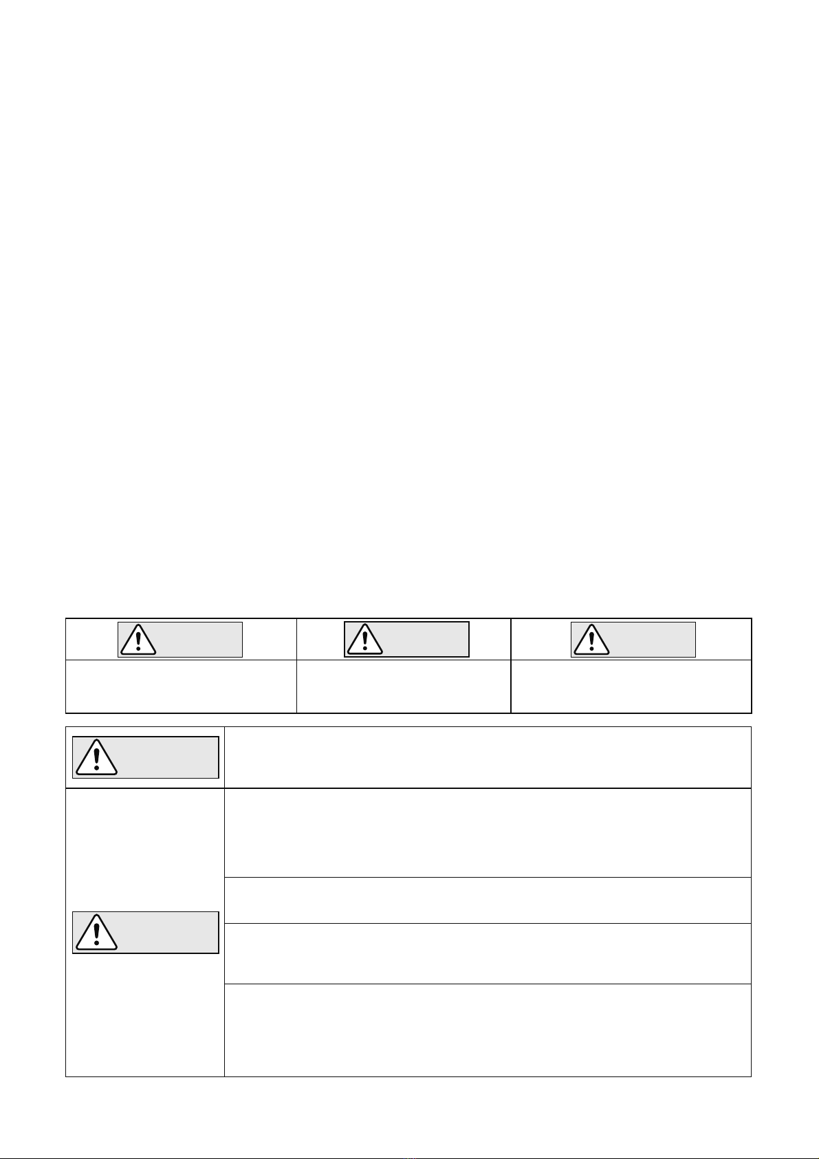
Indicates an urgent situation
which poses a threat of
death or serious injury.
Indicates that there is a
potential threat of death
or serious injury.
WARNING
CAUTION
WARNING
DANGER CAUTION
Indicates that there is a
possibility of injury or equip-
ment/product damage.
NEVER apply direct heat to the float. The float may explode due to
increased internal pressure, causing accidents leading to serious injury
or damage to property and equipment.
Install properly and DO NOT use this product outside the recommended
operating pressure, temperature and other specification ranges.
Improper use may result in such hazards as damage to the product or
malfunctions, which may lead to serious accidents. Local regulations may
restrict the use of this product to below the conditions quoted.
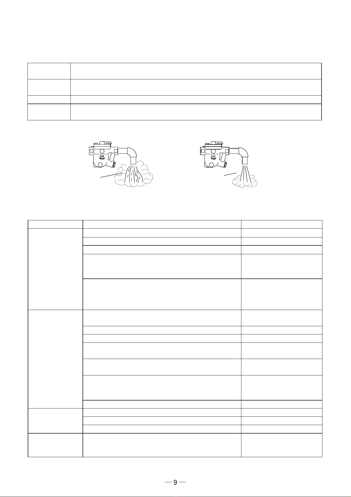
Take measures to prevent people from coming into direct contact
with product outlets. Failure to do so may result in burns or other injury
from the discharge of fluids.
DO NOT use this product in excess of the maximum operating
pressure differential. Such use could make discharge impossible.
When disassembling or removing the product, wait until the internal
pressure equals atmospheric pressure and the surface of the
product has cooled to room temperature. Disassembling or removing
the product when it is hot or under pressure may lead to discharge of
fluids, causing burns, other injuries or damage.
1