172-65255M-05 (A-COSR-10) 6 Oct 2021
Contents
Introduction ....................................................................... 1
Safety Considerations....................................................... 2
Specifications.................................................................... 4
Acceptable Operating Range............................................ 4
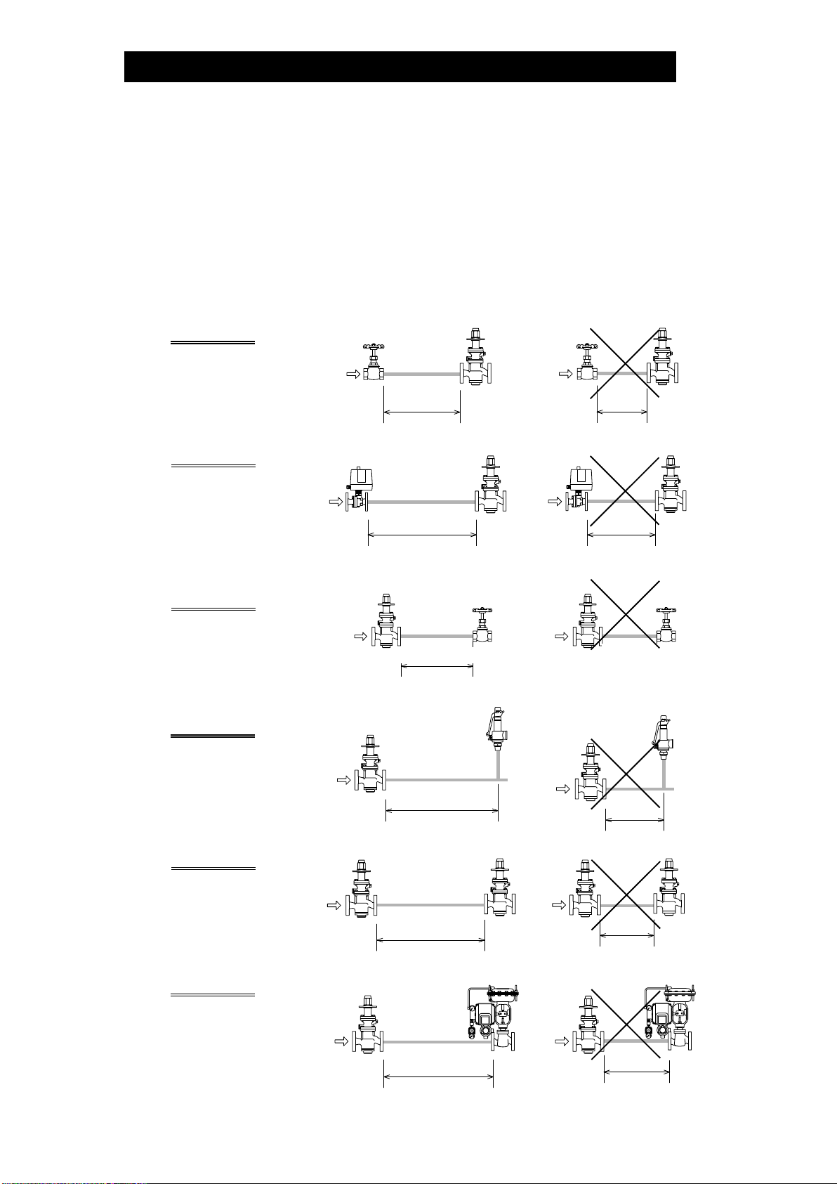
Correct Usage of the A-COSR Pressure Reducing Valve
.......................................................................................... 5
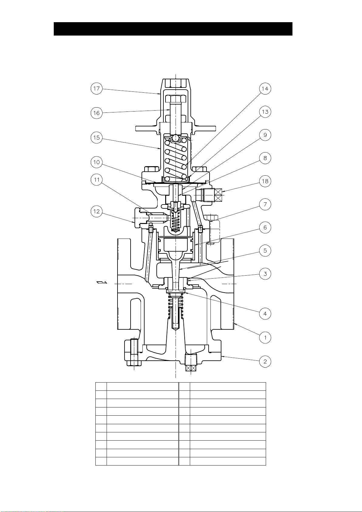
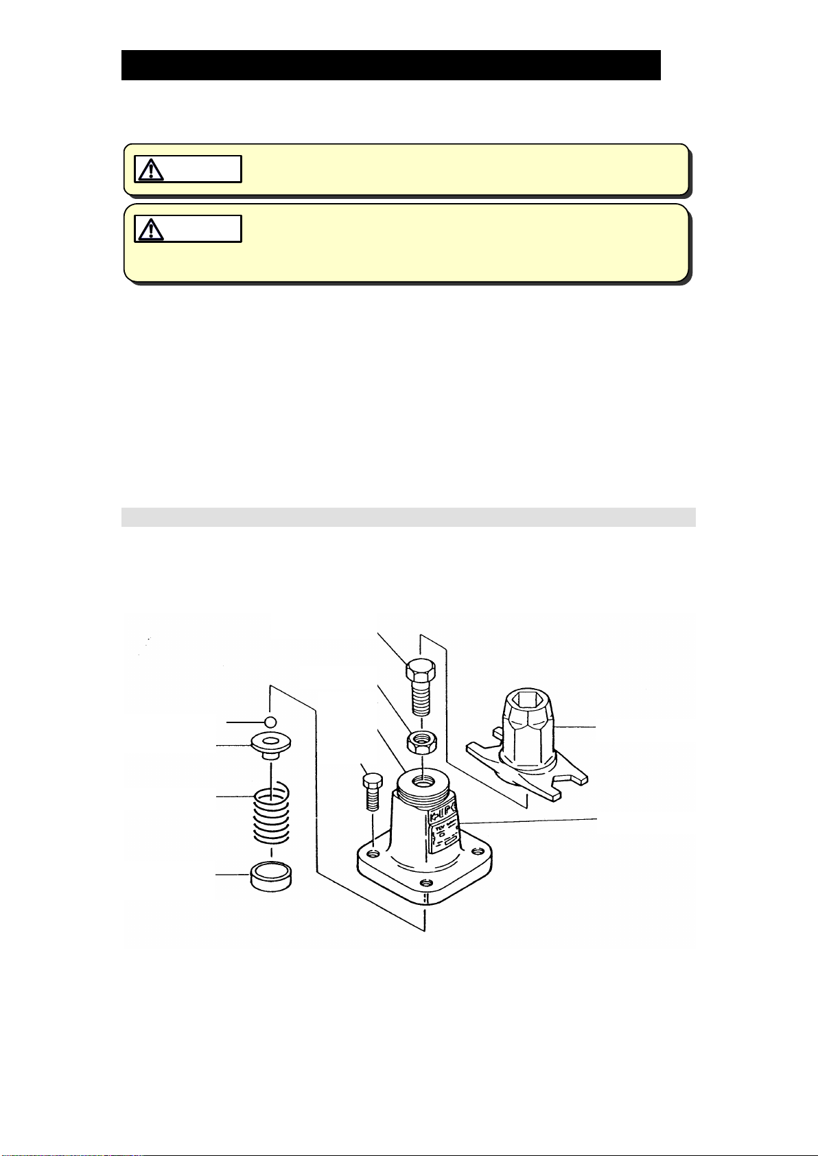
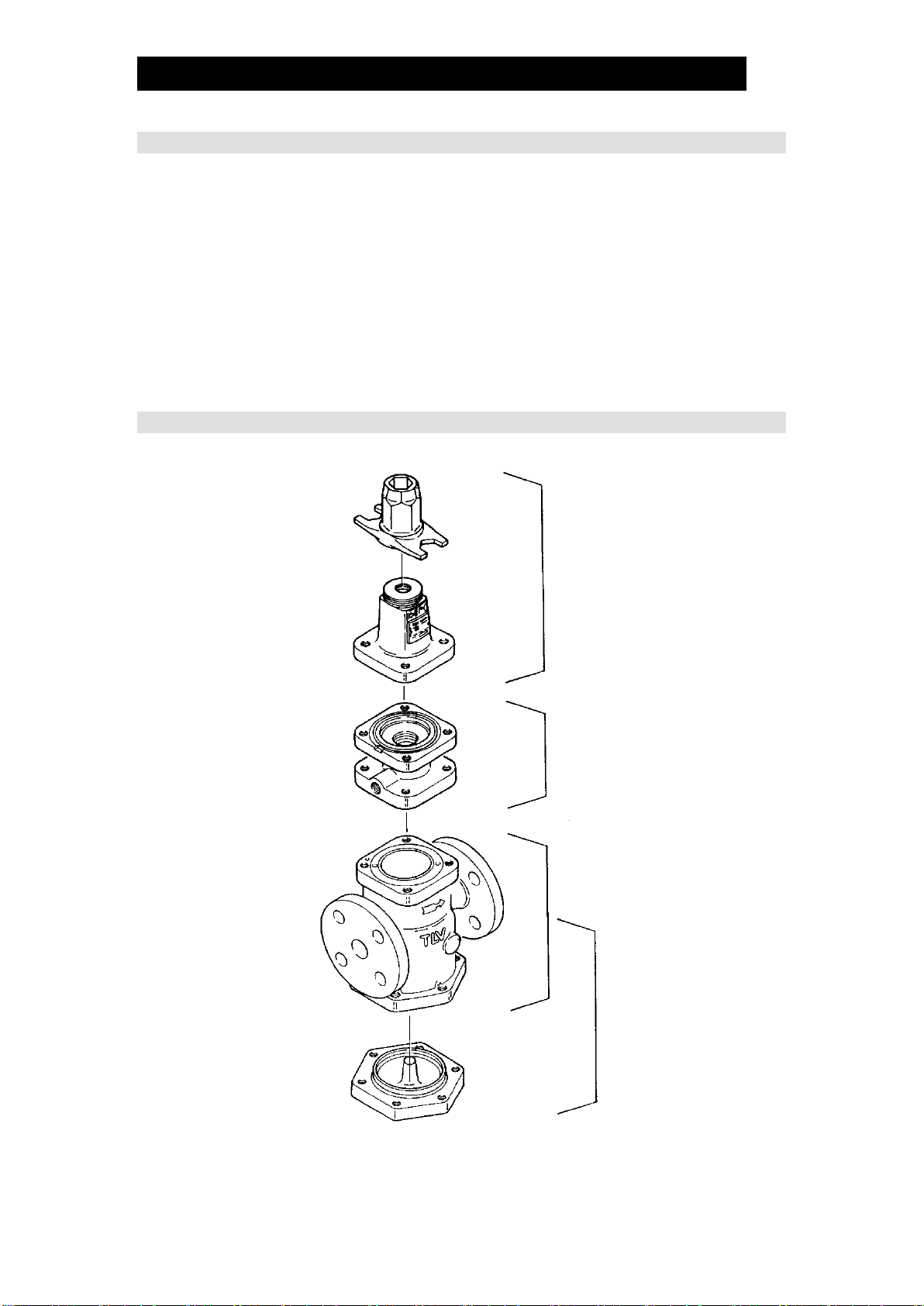
Configuration..................................................................... 7
Installation......................................................................... 8
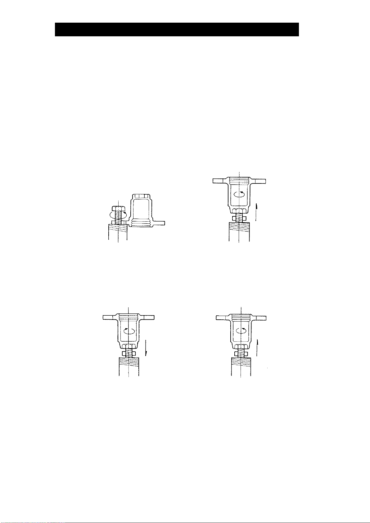
Adjustment ...................................................................... 12
Maintenance.................................................................... 13
Disassembly.................................................................... 14
Reassembly .................................................................... 18
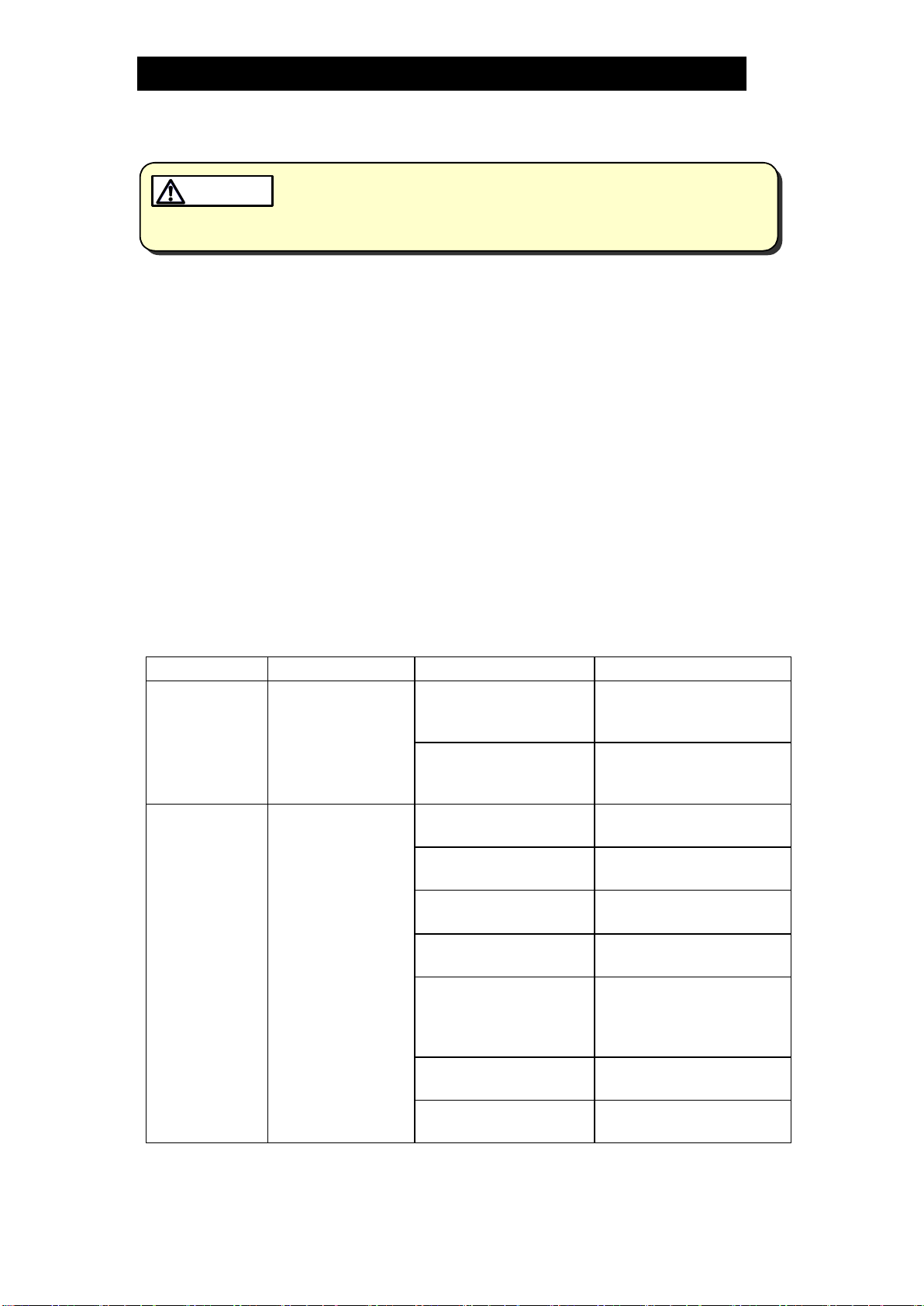
Troubleshooting .............................................................. 19
TLV EXPRESS LIMITED WARRANTY........................... 21
Service............................................................................ 23
Introduction
Thank you for purchasing the TLV A-COSR pressure reducing valve for air.
This product has been thoroughly inspected before being shipped from the
factory. When the product is delivered, before doing anything else, check the
specifications and external appearance to make sure nothing is out of the
ordinary. Also be sure to read this manual carefully before use and follow the
instructions to be sure of using the product properly.
The TLV pressure reducing valve for air, model A-COSR provides a more
stable secondary pressure than conventional reducing valves. The A-COSR
is designed for long service life, with all major components made of stainless
steel for superior durability.
If detailed instructions for special order specifications or options not contained
in this manual are required, please contact TLV for full details.
This instruction manual is intended for use with the model(s) listed on the front
cover. It is needed not only for installation, but also for subsequent
maintenance, disassembly/reassembly and troubleshooting. Please keep it in
a safe place for future reference.