TLV JH-P Series User manual
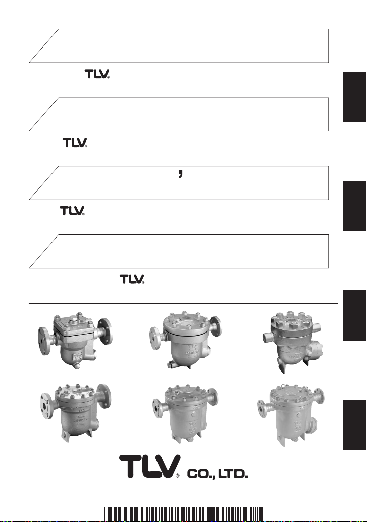
JH7RM-P
JH5RL-P
JH5RH-P
JH7.2R-P JH8R-P
JH7RH-P
JH7.5R-P
JH-P SERIES (OPTION: JH-W, -F, -V)
JH-P SERIE (OPTION: JH-W, -F, -V)
GAMME JH-P (OPTIONNEL: JH-W, -F, -V)
INSTRUCTION MANUAL
Keep this manual in a safe place for future reference
EINBAU- UND BETRIEBSANLEITUNG
Gebrauchsanleitung leicht zugänglich aufbewahren
MANUEL D UTILISATION
Conserver ce manuel dans un endroit facile d'accès
JH-P 系列 (选配件: JH-W, -F, -V)
操作说明书
请务必妥善保管此说明书,以备日后使用。
Copyright (C) 2020 by TLV CO., LTD. All rights reserved.
FREE FLOAT TYPE STEAM TRAPS
FREISCHWIMMER KONDENSATABLEITER
PURGEURS DE VAPEUR À FLOTTEUR FERMÉ LIBRE
自由浮球式蒸汽疏水阀
Deutsch
中
文
Français
English

Introduction
Before beginning installation or maintenance, please read this manual to ensure correct use of
the product. Keep the manual in a safe place for future reference.
This instruction manual is edited based on the JH-P Series (with cover plug). Information about
the JH-W Series (with socket welded cover connection), JH-F Series (with flanged cover
connection) and JH-V Series (with manual air vent valve) is also included.
The inline repairable JH-P Series steam traps are suitable for applications with the introduction of
almost no air (such as process systems and steam-using equipment under long continuous
operation, or superheated and saturated steam mains, branches and trace lines). The JH-P Series
can be used for small-to-large capacities and pressures up to 12 MPaG (1740 psig). The traps
discharge condensate continuously and automatically, at a temperature slightly lower than
saturation temperature.
1 MPa = 10.197 kg/cm2, 1 bar = 0.1 MPa
For products with special specifications or with options not included in this manual, contact TLV
for instructions.
The contents of this manual are subject to change without notice.
Einführung
Bitte lesen Sie die Betriebsanleitung vor Einbau und Inbetriebnahme sorgfältig durch und be-
wahren Sie sie für späteren Gebrauch an einem leicht zugänglichen Ort auf.
Die vorliegende Einbau- und Betriebsanleitung beschreibt in erster Linie Anweisungen für die
Modelle der JH-P-Serie (mit Entlüftungsanschluss Muffe). Sie dient ebenso dem Einbau und
Betrieb der Modellserien JH-W (Entlüftungsanschluss Schweißmuffe), JH-F (Entlüftungsanschluss
Flansch) und JH-V (für manuelles Entlüftungsventil).
Die Kondensatableiter der JH-P-Serie sind für praktisch luftfreie Anwendungen konzipiert, etwa für
Prozessanlagen, Anlagen mit ununterbrochen langen Betriebszeiten, Entwässerung überhitzter
oder gesättigter Dampfleitungen und Begleitheizungen. Die Anwendungsbreite reicht von kleinen
bis großen Kondensatmengen und Drücken bis 120 bar ü. „Frei-Schwimmer“-Kondensatableiter
führen das anfallende Kondensat mit nur geringer Unterkühlung kontinuierlich und gleichmäßig ab.
1 bar = 0,1 MPa
Wenden Sie sich an TLV für Sonderausführungen, die nicht in dieser Einbau- und
Betriebsanleitung enthalten sind.
Wir behalten uns vor, den Inhalt dieser Betriebsanleitung ohne Ankündigung zu ändern.
Introduction
Veuillez lire attentivement ce manuel afin d’utiliser correctement le produit.
Nous vous recommandons de le garder dans un endroit sûr pour de futures consultations.
Ce manuel d’instruction est édité pour le purgeur à flotteur fermé libre de la série JH-P (avec
bouchon de balayage). Les informations concernant les purgeurs JH-W (à souder), JHF (à brides),
et JH-V (avec évent d’air manuel), y sont également incluses.
Les purgeurs JH-P, réparables en ligne, sont faits pour des applications avec peu ou pas de
présence d’air (tel que process ou équipements travaillant en continu, ou encore pour la vapeur
surchauffée et aussi saturée, sur les lignes de distribution vapeur et de traçage).
La série JH-P peut être utilisée aussi bien pour des débits faibles qu’élevés et jusqu’à 120 bar.
Les purgeurs éliminent le condensât de manière continue et de façon automatique, à une
température légèrement inférieure à celle de la saturation de la vapeur.
1 bar = 0,1 MPa
Pour tout produit aux spécifications particulières ou comportant des options non reprises dans ce
manuel, veuillez contacter TLV.
Le contenu de ce manuel est sujet à modifications sans préavis.
1
Deutsch
Français
English
1. Safety Considerations
• Read this section carefully before use and be sure to follow the instructions.
• Installation, inspection, maintenance, repairs, disassembly, adjustment and valve
opening/closing should be carried out only by trained maintenance personnel.
• The precautions listed in this manual are designed to ensure safety and prevent equipment
damage and personal injury. For situations that may occur as a result of erroneous handling,
three different types of cautionary items are used to indicate the degree of urgency and the
scale of potential damage and danger: DANGER, WARNING and CAUTION.
• The three types of cautionary items above are very important for safety; be sure to observe
all of them, as they relate to installation, use, maintenance, and repair. Furthermore, TLV
accepts no responsibility for any accidents or damage occurring as a result of failure to
observe these precautions.
Indicates an urgent situation
which poses a threat of
death or serious injury.
Indicates that there is a
potential threat of death
or serious injury.
WARNING
CAUTION
WARNING
DANGER CAUTION
Indicates that there is a
possibility of injury or equip-
ment/product damage.
NEVER apply direct heat to the float. The float may explode due to
increased internal pressure, causing accidents leading to serious injury
or damage to property and equipment.
Install properly and DO NOT use this product outside the recommended
operating pressure, temperature and other specification ranges.
Improper use may result in such hazards as damage to the product or
malfunctions, which may lead to serious accidents. Local regulations may
restrict the use of this product to below the conditions quoted.
Take measures to prevent people from coming into direct contact
with product outlets. Failure to do so may result in burns or other injury
from the discharge of fluids.
Use hoisting equipment for heavy objects (weighing approximately
20 kg (44 lb) or more). Failure to do so may result in back strain or other
injury if the object should fall.
Use the eyebolts for removing the cover only; DO NOT use the
eyebolts for hoisting the product. Eyebolts may break under strain,
possibly resulting in serious injury.
DO NOT use this product in excess of the maximum operating
pressure differential. Such use could make discharge impossible.
When disassembling or removing the product, wait until the internal
pressure equals atmospheric pressure and the surface of the
product has cooled to room temperature. Disassembling or removing
the product when it is hot or under pressure may lead to discharge of
fluids, causing burns, other injuries or damage.
Be sure to use only the recommended components when repairing
the product, and NEVER attempt to modify the product in any way.
Failure to observe these precautions may result in damage to the product
or burns or other injury due to malfunction or the discharge of fluids.
Use only under conditions in which no freeze-up will occur. Freezing
may damage the product, leading to fluid discharge, which may cause
burns or other injury.
Use under conditions in which no water hammer will occur. The
impact of water hammer may damage the product, leading to fluid
discharge, which may cause burns or other injury.
2
English

Die Schwimmerkugel darf NICHT ERHITZT werden, da sie infolge
erhöhten Innendruckes platzen kann, was schwere Unfälle und
Verletzungen oder Beschädigung von Anlagen zur Folge hat.
1. Sicherheitshinweise
• Bitte lesen Sie dieses Kapitel vor Beginn der Arbeiten sorgfältig durch und befolgen Sie die
Vorschriften.
• Einbau und Ausbau, Inspektion, Wartungs- und Reparaturarbeiten, Öffnen und Schließen von
Armaturen, Einstellung von Komponenten, dürfen nur von geschultem Wartungspersonal
vorgenommen werden.
• Die Sicherheitshinweise in dieser Einbau- und Betriebsanleitung dienen dazu, Unfälle,
Verletzungen, Betriebsstörungen und Beschädigungen der Anlagen zu vermeiden. Für
Gefahrensituationen, die durch falsches Handeln entstehen können, werden drei verschiedene
Warnzeichen benutzt: GEFAHR; WARNUNG; VORSICHT.
• Diese drei Warnzeichen sind wichtig für Ihre Sicherheit. Sie müssen unbedingt beachtet werden,
um den sicheren Gebrauch des Produktes zu gewährleisten und Einbau, Wartung und
Reparatur ohne Unfälle oder Schäden durchführen zu können. TLV haftet nicht für Unfälle oder
Schäden, die durch Nichtbeachtung dieser Sicherheitshinweise entstehen.
Bedeutet, dass eine
unmittelbare Gefahr für Leib
und Leben besteht.
Bedeutet, dass die
Möglichkeit der Gefahr für
Leib und Leben besteht.
VORSICHT
WARNUNG
GEFAHR
GEFAHR
VORSICHT
Bedeutet, dass die Möglichkeit
von Verletzungen oder Schäden an
Anlagen oder Produkten besteht.
Die Einbauhinweise beachten und die spezifizierten Betriebsgrenzen
NICHT ÜBERSCHREITEN. Nichtbeachtung kann zu Betriebsstörungen
oder Unfällen führen. Lokale Vorschriften können zur Unterschreitung der
angegebenen Werte zwingen.
In sicherer Entfernung von Auslassöffnungen aufhalten und andere
Personen warnen, sich fernzuhalten. Nichtbeachtung kann zu
Verletzungen durch austretende Fluide führen.
Nur in frostsicherer Umgebung einsetzen. Einfrieren kann das Produkt
beschädigen, was zu Verbrennungen oder Verletzungen durch
austretende Fluide führt.
Nur an Stellen einbauen, an denen kein Wasserschlag eintreten
kann. Wasserschlag kann das Produkt beschädigen und zu
Verbrennungen oder Verletzungen durch austretende Fluide führen.
Für schwere Werkstücke (ca. 20 kg oder mehr) werden Hebezeuge
dringend empfohlen. Nichtbeachtung kann zu Rückenverletzungen oder
Verletzungen durch das herunterfallende Werkstück führen.
Die Ringschrauben nur zum Abheben des Gehäusedeckels benutzen,
NICHT zum Heben des gesamten Produkts. Ringschrauben können
unter Belastung brechen, was zu schweren Unfällen führen kann.
Maximalen Differenzdruck NICHT ÜBERSCHREITEN,
da sonst die Kondensatableitung unmöglich werden kann (Blockage).
Vor Öffnen des Gehäuses und Ausbau von Teilen warten, bis der
Innendruck sich auf Atmosphärendruck gesenkt hat und das
Gehäuse auf Raumtemperatur abgekühlt ist. Nichtbeachtung kann zu
Verbrennungen oder Verletzungen durch austretende Fluide führen.
Zur Reparatur nur Original-Ersatzteile verwenden und NICHT
VERSUCHEN, das Produkt zu verändern. Nichtbeachtung kann zu
Beschädigungen führen, die Betriebsstörungen, Verbrennungen oder
andere Verletzungen durch austretende Fluide verursachen.
3
Deutsch

1. Règles de sécurité
• Lire attentivement cette notice avant l'utilisation et suivre les instructions.
• Tout démontage, installation, entretien, contrôle et réparation doit être fait uniquement par une
personne formée à l'entretien.
• La liste des précautions à prendre est établie afin d'assurer votre sécurité et de prévenir des
dégâts matériels et/ou des blessures sérieuses. Dans certaines situations causées par une
mauvaise manipulation, trois indicateurs sont utilisés afin d'indiquer le degré d'urgence,
l'échelle du dommage potentiel et le danger : DANGER, AVERTISSEMENT et ATTENTION.
• Ces 3 indicateurs sont importants pour votre sécurité ; observez les précautions de sécurité
énumérées dans ce manuel pour l'installation, l'utilisation, l'entretien et la réparation du produit.
TLV n'accepte aucune responsabilité en cas d'accident ou de dommage survenant à la suite
d'un non-respect de ces précautions.
Indique une situation
d'urgence avec risque de
mort ou de blessure grave.
Indique une situation
pouvant entraîner la mort ou
des blessures graves.
AVERTISSEMENT
ATTENTION
AVERTISSEMENT
DANGER
ATTENTION
Indique un risque de blessure
ou de dégât matériel au
produit et/ou aux installations.
Installer le produit correctement et NE PAS utiliser ce produit en dehors
de la pression et de la température maximales de fonctionnement, ni en
dehors des autres plages spécifiées. Une telle utilisation peut entraîner
des dommages au produit ou des dysfonctionnements, ce qui peut
provoquer des brûlures ou autres blessures. Il se peut que des règlements
locaux limitent l'utilisation du produit en deçà des spécifications indiquées.
NE JAMAIS exposer le flotteur à la chaleur directement. Il pourrait
exploser suite à une pression interne accrue et causer des accidents
pouvant entraîner des blessures sérieuses ou des dégâts
matériels.
Prendre les mesures appropriées afin d’éviter que des personnes
n’entrent en contact direct avec les ouvertures du produit. Le non-
respect de cette règle peut provoquer des brûlures ou autres blessures
sérieuses dues à l'écoulement des fluides.
En cas de démontage ou de manipulation du produit, attendre que
la pression interne soit égale à la pression atmosphérique et que la
surface du produit soit complètement refroidie. Le non-respect de
cette règle peut provoquer des brûlures ou autres dommages dus à
l'écoulement des fluides.
En cas de réparation utiliser uniquement les pièces recommandées
et NE JAMAIS ESSAYER de modifier le produit. Le non- respect de
cette règle peut entraîner des dommages au produit, ou des brûlures et
autres blessures sérieuses dues au dysfonctionnement du produit ou à
l'écoulement des fluides.
Utiliser le produit dans des conditions où il n'y a aucun coup de
bélier. L'impact d'un coup de bélier peut endommager le produit et
provoquer l’écoulement des fluides, ainsi que des brûlures ou des
blessures graves.
Utiliser du matériel de levage adéquat pour les objets lourds (20 kg
et plus). Le non-respect de cette règle peut provoquer des douleurs
dans le dos ou des blessures si le produit venait à tomber.
Utiliser les anneaux de levage uniquement pour retirer le couvercle ;
NE PAS les utiliser pour soulever le produit. Ils peuvent se casser en
cas de surcharge, ce qui pourrait causer des blessures sérieuses.
NE PAS utiliser ce produit avec une pression différentielle
supérieure au maximum indiqué. Le non-respect de cette consigne
pourrait empêcher toute expulsion du condensât (blocage).
N’utiliser que dans des conditions où le gel ne se produit pas. Le gel
peut endommager le produit et provoquer l'écoulement des fluides, et
causer des brûlures ou autres blessures sérieuses.
4
Français

2. Configuration Aufbau Configuration
JH5RL-P / JH5RH-P JH7RM-P
JH7RH-P JH7.2R-P
JH7.5R-P
- F - V- W JH7RH-W
JH8R-P
Cover Connections Gehäusedeckelanschluss Raccordements de couvercle
10
○ ○
12
○
11
○
2○
14
○
15
○
13
○
16
○
5○
4○
7○
6
○
9
○
8
○
3
○
1
○
10
○
14
○
15
○
16
○
13
○
12
○
11
○
2
○
9
○
1
○
17
○
19
○
18
○
3○
5○
4○
7○
6
○
12
○
11
○
14
○
15
○
16
○
13
○
10
○
10
○
11
○
12
○
14
○
15
○
16
○
2○
17
○
13
○
9
○
2
○
9
○
3○
1○
4○
5○
7○
6○
22
○
21
○
23
○
24
○
17
○
20
○
19
○
18
○
1○
3○
5○
4○
7○
6
○
10
○
14
○
15
○
16
○
11
○
12
○
13
○
10
○
27
○
2
○
6
○
7
○
1
○
9
○
5○
4
○
12
○
11
○
16
○
14
○
15
○
13
○
26
○
25
○
22
○
21
○
26
○
25
○
17
○
3
○
4
○
9
○
23
○
24
○
18
○
19
○
1
○
5
○
7
○
6
○
2
○
23
○
17
○
24
○
3
○
18
○
19
○
30
○
31
○
29
○
32
○
28
○
33
○
32
(see pages 28-29) (siehe Seiten 28-29) (voir pages 28-29)
5
Deutsch
Français
English
No.
1
2
3
4
5
6
7
8
9
10
11
No.
23
24
25
26
27
28
29
30
31
32
33
Body
Cover
Float
Orifice
Orifice Gasket
Orifice Plug or Outlet Cover
Plug or Outlet Cover Gasket
Float Cover
Screen
Flange or Socket
Cover Bolt
Snap Ring
Screen Holder Retainer
Plug (Interior)
Plug Gasket (Interior)
Eye Bolt
Cover Socket**
Cover Flange**
Air Vent Valve Stem**
Steel Ball**
Air Vent Valve Body**
Air Vent Valve Gasket**
DescriptionDescription
Nr.
1
2
3
4
5
6
7
8
9
10
11
Nr.
23
24
25
26
27
28
29
30
31
32
33
Gehäuse
Gehäusedeckel
Schwimmerkugel
Ventilsitz
Ventilsitzdichtung
Ventilsitzstopfen oder
Ventilsitzdeckel
Stopfendichtung oder
Deckeldichtung
Schwimmerabdeckung
Schmutzsieb
Flansch oder Schweißmuffe
Gehäuseschraube
Spannring
Abstandsring
Stopfen (innen)
Stopfendichtung (innen)
Ringschraube
Deckelmuffe**
Deckelflansch**
Ventilspindel**
Stahlkugel**
Entlüftungsventilgehäuse**
Ventilgehäusedichtung**
BauteilBauteil Bauteil
* Optionnel pour JH5RL-P, JH5RH-P ** Optionnel (remplaçant désignations n° 21 et 22)
Cover Nut
Cover Gasket
Cover Plug
Cover Plug Gasket
Nameplate
Screen Holder
Drain Plug Gasket*
Drain Plug*
Orifice Locknut
Outlet Cover Bolt
Outlet Cover Nut
* Optional for JH5RL-P, JH5RH-P ** Optional (replace parts 8 and 9)
* Option für JH5RL-P, JH5RH-P ** Option (ersetzt Bauteile 14 und 15)
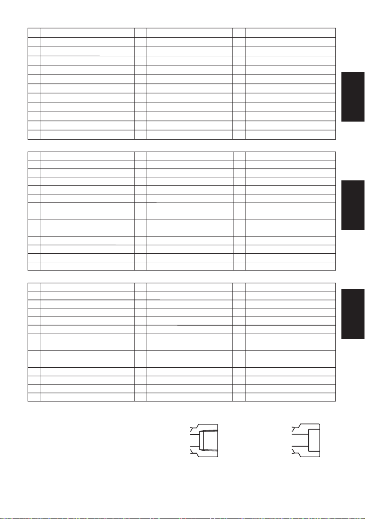
Screwed
Muffe
Taraud
é
Flanged: see page 5
Flansch: siehe Seite 5
À brides : voir page 5
Socket Weld
Schweißmuffe
Douille
à
soude
r
Connection Anschluss Raccordements
No.
12
13
14
15
16
17
18
19
20
21
22
N°
1
2
3
4
5
6
7
8
9
10
11
N°
23
24
25
26
27
28
29
30
31
32
33
Corps
Couvercle
Flotteur
Orifice
Joint d’orifice
Bouchon d’orifice ou
couvercle d’orifice
Joint de bouchon ou joint de
couvercle
Capot de flotteur
Crépine
Bride ou douille à souder
Boulon de couvercle
Anneau élastique
Bague d’écartement
Bouchon (intérieur)
Joint de bouchon (intérieur)
Anneau de levage
Douille de couvercle**
Bride de couvercle**
Tige du robinet d’air**
Boule en acier**
Corps du robinet d’air**
Joint du robinet d’air**
DésignationDésignation Désignation
N°
12
13
14
15
16
17
18
19
20
21
22
Écrou de couvercle
Joint de couvercle
Bouchon de couvercle
Joint bouchon de couvercle
Plaquette nominative
Porte-crépine
Joint de bouchon vidange*
Bouchon de vidange*
Contre-écrou d’orifice
Boulon de couvercle d’orifice
Écrou de couvercle d’orifice
KA-Gehäusemutter
Gehäusedichtung
Deckelstopfen
Deckelstopfendichtung
Typenschild
Siebhalterung
Stopfendichtung*
Entwässerungsstopfen*
Verschlussmutter
Ventilsitzdeckelschraube
Ventilsitzdeckelmutter
Nr.
12
13
14
15
16
17
18
19
20
21
22
Description
6
Deutsch
Français
English

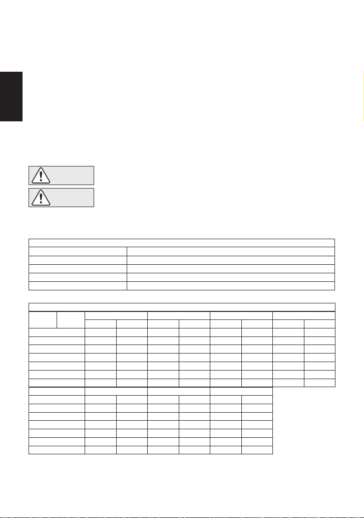
3. Specifications Technische Daten Données techniques
To avoid malfunctions, product damage, accidents or serious injury, install
properly and DO NOT use this product outside the specification range. Local
regulations may restrict the use of this product to below the conditions quoted.
Die Einbauhinweise beachten und die spezifizierten Betriebsgrenzen NICHT
ÜBERSCHREITEN. Nichtbeachtung kann zu Betriebsstörungen oder Unfällen führen.
Lokale Vorschriften können zur Unterschreitung der angegebenen Werte zwingen.
VORSICHT
Installer le produit correctement et NE PAS l’utiliser en dehors des plages
spécifiées. En cas de dépassement des limites données, des dysfonctionnements
ou accidents pourraient survenir. Il se peut que des règlements locaux limitent
l'utilisation du produit en deçà des spécifications indiquées.
ATTENTION
CAUTION
Refer to the product nameplate for detailed specifications.
Die technischen Daten stehen auf dem Typenschild.
Les données techniques sont inscrites sur la plaquette nominative.
* Maximum allowable pressure (PMA) and maximum allowable temperature (TMA) are
PRESSURE SHELL DESIGN CONDITIONS, NOT OPERATING CONDITIONS.
** "Valve No." is displayed for products with options. This item is omitted from the
nameplate when there are no options.
* Maximal zulässiger Druck (PMA) und maximal zulässige Temperatur (TMA) sind
AUSLEGUNGSDATEN NICHT BETRIEBSDATEN.
** Die "Valve No." wird angegeben bei Typen mit Optionen. Bei Typen ohne Optionen bleibt
diese Stelle frei.
* Pression maximale admissible (PMA) et Température maximale admissible (TMA) sont les
CONDITIONS DE CALCUL DU CORPS, PAS LES CONDITIONS DE FONCTIONNEMENT.
** Le "Valve No." est indiqué pour des modèles avec options. Ce numéro ne figure pas sur les
modèles sans options.
G Production Lot No.
Fertigungslos-Nr.
Lot de production n°
H Valve No.**
C Maximum Allowable Pressure*
Maximal zulässiger Druck*
Pression maximale admissible*
F Maximum Operating Temperature
Maximale Betriebstemperatur
Temp. de fonctionnement maximale
D Maximum Allowable Temperature*
Maximal zulässige Temperatur*
Température maximale admissible*
A Model
Typ
Modèle
E Maximum Differential Pressure
Maximaler Differenzdruck
Pression différentielle maximale
B Nominal Diameter
Größe/DN
Dimension/DN
B
A
G
D
E
A
D
E
H
H
C
F
C
B
F
G
7
Deutsch
Français
English
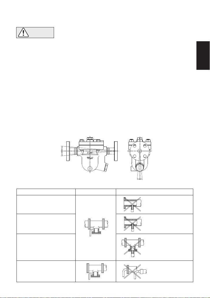
5. Piping Arrangement
Requirement
Install a catchpot with the
proper diameter.
Diameter is too
small.
Diameter is too
small and inlet
protrudes into pipe.
Rust and scale
flow into the trap
with the
condensate.
Condensate
collects in the
pipe.
Make sure the flow of
condensate is not
obstructed.
To prevent rust and scale
from flowing into the trap,
connect the inlet pipe
25-50 mm (1-2 in.) above
the base of the T - pipe.
When installing on the
blind end, make sure
nothing obstructs the flow
of condensate.
Correct Incorrect
4. Proper Installation
• Installation, inspection, maintenance, repairs, disassembly, adjustment
and valve opening/closing should be carried out only by trained
maintenance personnel.
• Take measures to prevent people from coming into direct contact with
product outlets.
• Use the eyebolts for removing the cover only; DO NOT use the eyebolts
for hoisting the product.
• Install for use under conditions in which no freeze-up will occur.
• Install for use under conditions in which no water hammer will occur.
Allowable Inclination
CAUTION
Continued page 9
1.
Before installation, be sure to remove all protective seals.
2.
Before installing the trap, blow out the inlet piping to remove all dirt and oil.
3. When hoisting the product, hang the rope around the inlet/outlet as close to the body as
possible.
4. Install the steam trap within the allowable inclination, as shown below. Also make sure that
the arrow mark on the body corresponds with the direction of flow.
5.
Install the trap in the lowest part of the pipeline or equipment so the condensate flows naturally
into the trap by gravity. The inlet pipe should be as short and have as few bends as possible.
6.
Support the pipes properly within 800 mm (2.5 ft) on either side of the trap.
7.
Install a bypass valve to discharge condensate, and inlet and outlet valves to isolate the trap in
the event of trap failure or when performing maintenance.
8.
Install a check valve at the trap outlet whenever more than one trap is connected to the
condensate collection pipeline.
9.
The use of unions is recommended to facilitate connection and disconnection of screwed
models.
5˚5˚
5˚ 5˚
8
English
( )
( )
( )
(1)
(1)
( )
36
60
24
26
26
27
1. Is the pipe diameter suitable?
2. Has the trap been installed within the allowable inclination and with the arrow on the body
pointing in the direction of flow?
3. Has sufficient space been secured for maintenance?
4. Have maintenance valves been installed at inlet and outlet? If the outlet is subject to back
pressure, has a check valve been installed?
5. Is the inlet pipe as short as possible, with as few bends as possible, and installed so that the
condensate will flow naturally down into the trap?
6. Has the piping work been done with the proper methods, as shown in the table on page 8?
Check to make sure that the pipes connected to the trap have been installed properly.
Operational inspections should be performed at least twice per year, or as called for by trap
operating conditions. Steam trap failure may result in temperature drop in the equipment, poor
product quality or losses due to steam leakage.
6. Inspection and Maintenance
WARNING
NEVER apply direct heat to the float. The float may explode due to
increased internal pressure, causing accidents leading to serious injury or
property and equipment damage.
• Installation, inspection, maintenance, repairs, disassembly, adjustment
and valve opening/closing should be carried out only by trained
maintenance personnel.
• Before attempting to open the trap, close the inlet and outlet isolation valves and wait until the
trap has cooled completely. Failure to do so may result in burns.
• Be sure to use the proper components and NEVER attempt to modify the product.
CAUTION
Body, Cover (s)
Gaskets
Screen
Float
Valve Seat
Check inside for damage, dirt, grease, oil film, rust or scale
Check for warping or damage
Check for clogging, corrosion or damage
Check for deformation, damage, oil film or water inside
Check for rust, scale, oil film, wear or damage
Parts Inspection Procedure
Tightening Torque and Distance Across Flats
Parts &
Number Model
Cover Nut 12
Orifice 4
Orifice Plug 6
Outlet Cover Nut 22
Drain Plug 19*
Orifice Locknut 20
Cover Plug 14
Model
Cover Nut 12
Orifice 4
Orifice Plug 6
Outlet Cover Nut 22
Drain Plug 19*
Cover Plug 14
Plug (Interior) 25 1 N·m 10 kg·cm
JH5RL-P
160
140
180
35
100
(115)
(100)
(130)
(26)
(73)
22
17
38
21
26
( )
( )
( )
( )
(1)
* Option for JH5RL-P, JH5RH-P
If drawings or other special documentation were supplied for the product, any torque given there
takes precedence over values shown here.
/32
21
/
16
13
/8
7
/2
1
1
JH5RH-P
170
140
180
35
100
(125)
(100)
(130)
(26)
(73)
24
17
38
21
26
( )
( )
( )
( )
(1)
mm (in)
N·m(lbf·ft)
/32
21
/32
31
/16
13
/16
15
/2
1
1
JH7RM-P
200
280
420
100
100
(150)
(205)
(310)
(73)
(73)
24
26
50
26
26
( )
(1)
( )
(1)
(1)
mm (in)
N·m(lbf·ft)
/16
15
JH7RH-P
700
200
250
100
(510)
(150)
(185)
(73)
46
30
32
26
( )
( )
( )
(1)
mm (in)
N·m(lbf·ft)
/4
1
1
/
16
13
1
/
16
3
1
JH7.2R-P
180
350
700
100
100
(130)
(260)
(510)
(73)
(73)
24
38
46
26
26
( )
( )
( )
(1)
(1)
/16
15
/2
1
1
/8
3
2
JH7.5R-P
200
600
800
100
100
150
(150)
(440)
(590)
(73)
(73)
(110)
30
46
46
26
26
27
( )
( )
( )
(1)
(1)
( )
JH8R-P
450
1000
160
100
100
150
(330)
(730)
(115)
(73)
(73)
(110)
/
16
13
1
/
16
13
1
/
16
13
1
/
32
13
1
/16
1
1
/16
3
1
/16
15
/16
1
1
N·m(lbf·ft) mm (in)
1
9
English
During Disassembly During Reassembly
Coat threads with anti-seize
and tighten to the proper
torque
* Option
** Must remove Plug (Interior) 25 (JH7.5R-P, JH8R-P only) before this part can be removed or inserted
Part & No.
JH7RH-P JH7.5R-P
JH8R-P
JH5RL-P
JH5RH-P JH7RM-P
JH7.2R-P
Disassembly / Reassembly (to reassemble, follow procedures in reverse)
Drain Plug 19
Drain Plug
Gasket 18
Cover Nut 12
Cover 2
Cover Gasket 13
Cover Plug 14
Cover Plug
Gasket 15
Plug (Interior) 25
Plug Gasket
(Interior) 26
Snap Ring 23
Screen 9 &
Float Cover 8
Screen 9
Screen Holder
Retainer 24
Screen Holder 17
Float 3
Orifice Plug 6
Orifice Plug
Gasket 7
Outlet Cover
Nut 22
Outlet Cover 6
Outlet Cover
Gasket 7
Orifice
Locknut 20
Orifice 4
Orifice Gasket 5
Use a wrench to remove
Remove gasket and
clean sealing surfaces
Use a wrench to remove
Use a wrench to remove
Remove (use all 4 eye bolts
for JH8R-P to hoist the cover)
Remove gasket and clean
sealing surfaces
Remove gasket and clean
sealing surfaces
Use a wrench to remove
Remove gasket and clean
sealing surfaces
Use appropriate pliers
Lift straight up
Lift straight up while turning
Lift straight up
Remove without bending
Remove, careful not to
scratch grounded surface
Use a wrench to remove
Remove gasket and clean
sealing surfaces
Use a wrench to remove
Remove
Remove gasket and clean
sealing surfaces
Use a wrench to remove
(may require extension bar)
Use a wrench to remove
Remove from interior
Remove gasket and clean
sealing surfaces
Replace with a new gasket
(see page 12)
Replace with a new gasket,
coat surfaces with anti-seize
Fix with Orifice Locknut
(see page 12)
Coat threads with anti-seize
and tighten to the proper
torque
Coat threads with anti-seize
and tighten to the proper
torque (see page 12)
Replace with a new gasket, do
not apply anti-seize
Attach
Coat threads with anti-seize
and tighten to the proper
torque
Replace with a new gasket,
coat surfaces with anti-seize
Coat threads with anti-seize
and tighten to the proper
torque
Insert into body, being careful
not to scratch its grounded
surface
Place screen holder on ledge
inside body, round side up;
place screen holder retainer
next (if applicable), followed by
screen
Align arrows and insert, insert
tab on bottom into guide on
body and push in until top is
flush
Insert securely into groove
Replace with a new gasket,
coat surfaces with anti-seize
Coat threads with anti-seize
and tighten to the proper torque
Replace with a new gasket,
coat surfaces with anti-seize
Coat threads with anti-seize
and tighten to the proper
torque
Replace with a new gasket, do
not apply anti-seize
Align cover with the connector
or the arrow on the body and
attach
Coat threads with anti-seize
and tighten to the proper
torque
Replace with a new gasket,
coat surfaces with anti-seize
*
*
**
** **
** **
** **
**
10
English
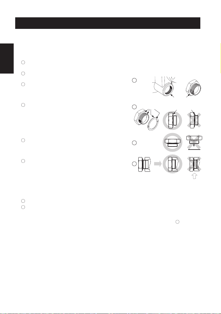
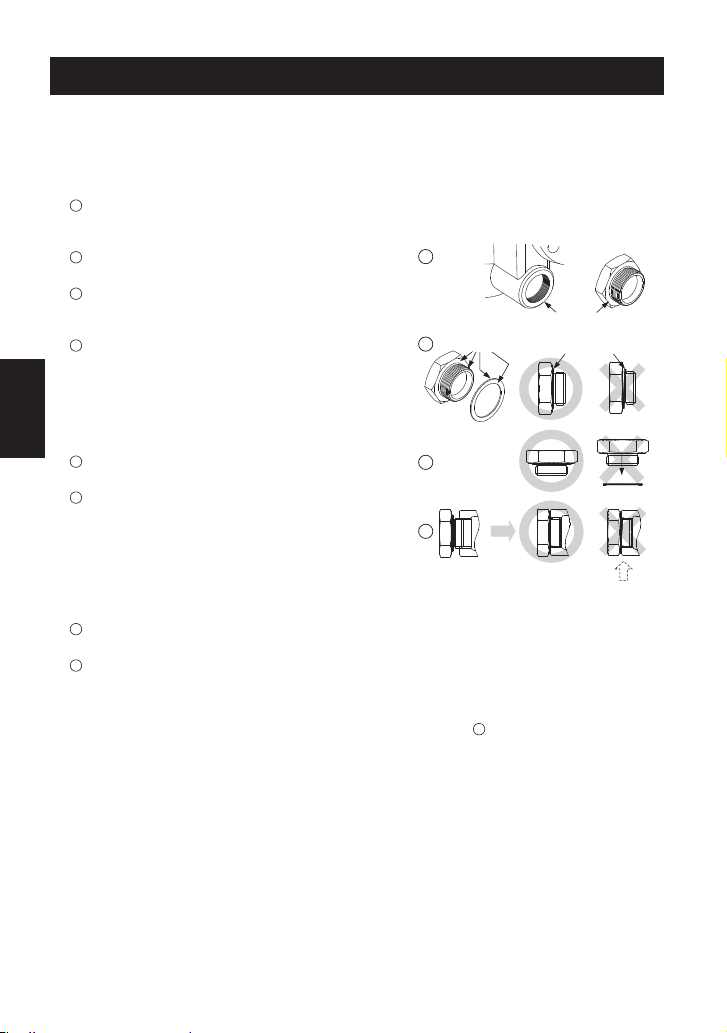
Instructions for Plug / Holder Disassembly and Reassembly
The seal on the threaded plugs/holders found on TLV products is formed by a flat metal
gasket. There are various installation orientations for the gaskets, such as horizontal,
diagonal and downward, and the gasket may be pinched in the thread recesses during
assembly.
Instructions for Disassembly and Reassembly
1Remove the plug/holder using a tool of the specified
size (distance across flats).
2The gasket should not be reused. Be sure to
replace it with a new gasket.
3Clean the gasket surfaces of the plug/holder and the
product body using a rag and/or cleaning agents, then
check to make sure the surfaces are not scratched or
deformed.
4Coat both the gasket surface of the plug/holder and
the threads of the plug/holder with anti-seize, then
press the gasket onto the center of the gasket
surface of the plug/holder, making sure the
anti-seize affixes the gasket tightly to the
plug/holder. Check to make sure the gasket is not
caught in the recesses of the threads.
5Hold the plug/holder upside down to make sure that
the anti-seize makes the gasket stick to the
plug/holder even when the plug/holder is held
upside down.
6Screw the plug/holder by hand into the product body
while making sure that the gasket remains tightly
affixed to the center of the gasket surface of the
plug/holder. Make sure the entire gasket is making
contact with the gasket surface of the product body.
It is important at this point to make sure the gasket
is not pinched in the thread recesses of the
plug/holder.
7Tighten the plug/holder to the proper torque.
8Next, begin the supply of steam and check to make sure there is no leakage from the part
just tightened. If there is leakage, immediately close the inlet valve and, if there is a bypass
valve, take the necessary steps to release any residual pressure. After the surface of the
product cools to room temperature, repeat the procedure beginning from step 1.
3
5
6
Gasket
Do not pinch gasket
in thread recesses
4Coat with anti-seize
Gasket Surface
11
English

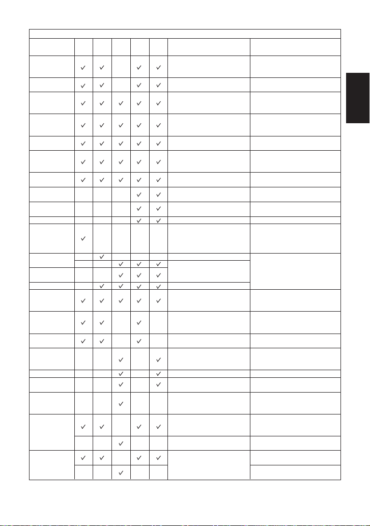
7. Maintenance Parts and Repair Parts
Maintenance parts and repair parts are available from TLV only in kits, as shown below.
Maintenance Kit: M
Repair Kit: R
Orifice 4
Orifice Gasket 5
Orifice Plug Gasket or
Outlet Cover Gasket 7
Float Cover 8
Screen 9
Cover Gasket 13
Cover Plug Gasket 15
Drain Plug Gasket* 18
Lock Nut 20
Plug Gasket (Interior) 26
JH5RL-P
JH5RH-P
MRMRMRMRMRMR
JH7RM-P JH7RH-P JH7.2R-P JH7.5R-P JH8R-P
Replacement float available.
Air Vent Valve Replacement units available for optional JH-V models.
* Option for JH5RL-P, JH5RH-P
8. Operational Check
A visual inspection can be carried out to aid in determining the necessity for immediate
maintenance or repair, if the trap is open to atmosphere. If the trap does not discharge to
atmosphere, use diagnostic equipment such as TLV TrapMan or TLV Pocket TrapMan (within
their pressure and temperature measurement range).
NOTES for JH7RH-P:
Special Points Pertaining to Orifice and Orifice Gasket Reassembly
Follow the steps below when inserting the orifice into the body in order to ensure that the gasket
does not fall off and is inserted correctly without protruding from the groove.
1. First, insert the orifice alone into the orifice-housing section of the body, in order to
ascertain how much of it should be sticking out.
2. Take the orifice out again, and then fill the groove in the orifice with water and insert the
gasket. The surface tension of the water will now hold the gasket in place, and it will not
fall out even if the orifice is pointed downwards.
3. Without altering anything, insert it into the orifice-housing section of the body and check to
make sure that the amount of orifice sticking out of the body is the same as the amount
that was sticking out when only the orifice was inserted in step 1.
4. Hold it in that position by hand and, after hand-tightening the orifice locknut from the
outlet side, hold the orifice in place from the body float chamber side using a drive wrench
and then tighten the orifice locknut to the proper torque using a torque wrench.
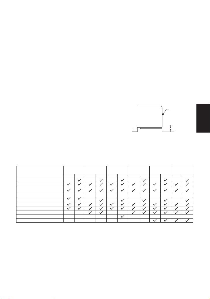
Special Points Pertaining to Cover and Outlet Cover Reassembly
1. After operation following disassembly and reassembly,
it is recommended that the trap be let to sit for a day
and then receive additional tightening.
2. Using the tightening torques for the cover nuts and
outlet cover nuts as a reference, tighten until the cover
and outlet cover gaps are uniform. The gaps should be
1.5 mm (1/16”) or less. Body
Cover or
Outlet Cover
1.5mm( ”)
/16
1
12
English

No condensate
is discharged
(blocked)
or discharge
is poor
Replace the float
Check specifications and reselect
trap suitable for actual flow
Air binding has occurred Perform a bypass blowdown or
consider switching to a product with
a built-in air vent or air vent valve
Rust and scale have accumulated
around the orifice or under the float Clean
Improper tightening torque for cover
was used Tighten to the proper torque
Water hammer occurs Examine the piping for problems that
can cause water hammer
Float is deformed or coated with scale
Orifice is damaged
Clean or replace the float
Replace with new orifice
Trap is installed above the maximum
allowable inclination angle
Vibration of trap occurs
Correct the installation
Lengthen inlet piping, then fasten it securely
Deterioration of or damage to gaskets Replace with new gaskets
Leakage from eroded cavities of body
or cover Replace the trap
Flow exceeds rated capacity of the trap
Blowdown through the bypass or
close the trap inlet valve and allow
the trap to cool
Compare specifications and actual
operating conditions
Clean
9. Troubleshooting
If the expected performance is unachievable after installation of the steam trap, read chapters 4
and 5 again and check the following points to take appropriate corrective measures.
Instruction Manual is continued on page 28.
Steam is
discharged or
leaks from the
trap outlet
(blowing)
(steam leakage)
Float is damaged or filled with
condensate
Orifice, screen or piping are clogged
with rust or scale
Steam-locking has occurred
Float is frequently
damaged
Steam leaks
from a place
other than
the trap outlet
The trap operating pressure exceeds
the maximum specified pressure, or
there is insufficient pressure differential
between the trap inlet and outlet
Problem Cause Remedy
Flash Steam
White jet
containing
water droplets
Live Steam Leakage
Clear, slightly
bluish jet
Normal: Condensate is discharged continuously with flash steam and the sound
of flow can be heard. If there is very little condensate, there is almost no
sound of flow.
Blocked: No condensate is discharged. The trap is quiet and makes no noise,
and the surface temperature of the trap is low.
Blowing: Live steam continually flows from the outlet and there is a continuous
metallic sound.
Live steam is discharged through the trap outlet together with the
condensate and there is a high-pitched sound.
(When conducting a visual inspection, flash steam is sometimes mistaken for steam leakage. For
this reason, the use of a steam trap diagnostic instrument such as TLV TrapMan is highly
recommended.)
Steam
Leakage:
13
English
4. Einbauhinweise
•
Einbau und Ausbau, Inspektion, Wartungs- und Reparaturarbeiten, Öffnen
und Schließen von Armaturen, Einstellung von Komponenten, dürfen nur
von geschultem Wartungspersonal vorgenommen werden.
•
In sicherer Enfernung von Auslassöffnungen aufhalten und andere Personen
warnen, sich fern zu halten.
•
Die Ringschrauben nur zum Abheben des Gehäusedeckels benutzen,
NICHT zum Heben des gesamten Produkts.
•
Kondensatableiter in frostsicherer Umgebung einbauen.
•
Kondensatableiter nur dort einbauen, wo kein Wasserschlag eintreten kann.
VORSICHT
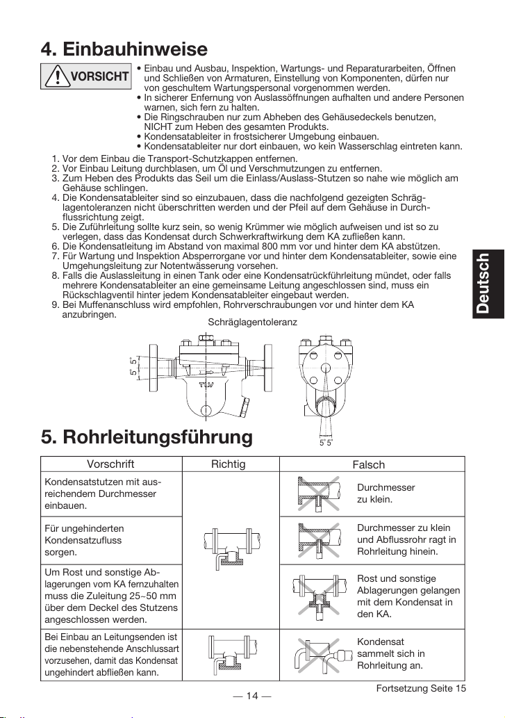
5. Rohrleitungsführung
Vorschrift
Kondensatstutzen mit aus-
reichendem Durchmesser
einbauen.
Durchmesser
zu klein.
Durchmesser zu klein
und Abflussrohr ragt in
Rohrleitung hinein.
Rost und sonstige
Ablagerungen gelangen
mit dem Kondensat in
den KA.
Kondensat
sammelt sich in
Rohrleitung an.
Für ungehinderten
Kondensatzufluss
sorgen.
Um Rost und sonstige Ab-
lagerungen vom KA fernzuhalten
muss die Zuleitung 25~50 mm
über dem Deckel des Stutzens
angeschlossen werden.
Bei Einbau an Leitungsenden ist
die nebenstehende Anschlussart
vorzusehen, damit das Kondensat
ungehindert abfließen kann.
Richtig Falsch
Fortsetzung Seite 15
Schräglagentoleranz
1.
Vor dem Einbau die Transport-Schutzkappen entfernen.
2.
Vor Einbau Leitung durchblasen, um Öl und Verschmutzungen zu entfernen.
3. Zum Heben des Produkts das Seil um die Einlass/Auslass-Stutzen so nahe wie möglich am
Gehäuse schlingen.
4. Die Kondensatableiter sind so einzubauen, dass die nachfolgend gezeigten Schräg-
lagentoleranzen nicht überschritten werden und der Pfeil auf dem Gehäuse in Durch-
flussrichtung zeigt.
5.
Die Zuführleitung sollte kurz sein, so wenig Krümmer wie möglich aufweisen und ist so zu
verlegen, dass das Kondensat durch Schwerkraftwirkung dem KA zufließen kann.
6.
Die Kondensatleitung im Abstand von maximal 800 mm vor und hinter dem KA abstützen.
7.
Für Wartung und Inspektion Absperrorgane vor und hinter dem Kondensatableiter, sowie eine
Umgehungsleitung zur Notentwässerung vorsehen.
8.
Falls die Auslassleitung in einen Tank oder eine Kondensatrückführleitung mündet, oder falls
mehrere Kondensatableiter an eine gemeinsame Leitung angeschlossen sind, muss ein
Rückschlagventil hinter jedem Kondensatableiter eingebaut werden.
9.
Bei Muffenanschluss wird empfohlen, Rohrverschraubungen vor und hinter dem KA
anzubringen.
5˚5˚
5˚ 5˚
14
Deutsch

1. Ist die Nennweite groß genug?
2. Wurde der KA horizontal, bzw. Innerhalb der Schräglagentoleranz und mit dem Pfeil in
Durchflussrichtung eingebaut?
3. Ist genügend Platz für Wartungsarbeiten vorhanden?
4. Wurden vor und hinter dem KA Absperrarmaturen eingebaut? Falls Gegendruck besteht,
wurde ein Rückschlagventil eingebaut?
5. Ist die Zuleitung so kurz wie möglich, hat sie so wenig Krümmer wie möglich und kann das
Kondensat durch Schwerkraft zufließen?
6. Wurden die Rohrleitungen so ausgeführt, wie auf Seite 14 beschrieben?
Stellen Sie sicher, dass die Rohrleitungsarbeiten richtig ausgeführt wurden und dass der KA wie
beschrieben, eingebaut wurde:
Gehäuse, Deckel
Dichtungen
Schmutzsieb
Schwimmerkugel
Ventilsitz
Auf Ablagerungen, Rost, Schmutz, Ölfilm prüfen
Auf Verformung oder Beschädigung prüfen
Auf Verstopfung, Ablagerungen, Beschädigung prüfen
Auf Verformung, Beschädigung oder Wasser in der Kugel prüfen
Auf Ablagerungen, Rost, Schmutz, Ölfilm prüfen
Überprüfung der Einzelteile
Es wird empfohlen, mindestens zweimal pro Jahr, oder je nach Betriebsweise in kürzeren
Zeitabständen, eine Inspektion durchzuführen.
6. Inspektion und Wartung
GEFAHR Um Unfälle und Verletzungen zu vermeiden, darf die Schwimmerkugel
NICHT ERHITZT WERDEN; da sie infolge erhöhten Innendrucks platzen
kann.
VORSICHT
Bauteil & Nr.
KA-Gehäusemutter 12
Ventilsitz 4
Ventilsitzstopfen 6
Ventilsitzdeckelmutter 22
Entwässerungsstopfen 19*
Verschlussmutter 20
Deckelstopfen 14
Stopfen (innen) 25
160
140
180
35
100
22
17
38
21
26
170
140
180
35
100
24
17
38
21
26
200
280
420
100
100
24
26
50
26
26
700
200
250
100
46
30
32
26
180
350
700
100
100
24
38
46
26
26
200
600
800
100
100
150
30
46
46
26
26
27
450
1000
160
100
100
150
36
60
24
26
26
27
JH5RL-P JH5RH-P JH7RM-P JH7RH-P JH7.2R-P JH7.5R-P JH8R-P
Anzugsmomente und Schlüsselweiten
N.m mm N.m mm N.m mm N.m mm N.m mm N.m mm N.m mm
* Option für JH5RL-P, JH5RH-P
Falls Zeichnungen oder andere spezielle Dokumente mit dem Produkt geliefert wurden, haben An-
gaben über Anzugsmomente in diesen Unterlagen Vorrang vor den hier gezeigten Anzugsmomenten.
• Einbau und Ausbau, Inspektion, Wartungs- und Reparaturarbeiten, Öffnen
und Schließen von Armaturen, Einstellung von Komponenten, dürfen nur
von geschultem Wartungspersonal vorgenommen werden.
• Vor dem Öffnen des Kondensatableiters sind die Absperrarmaturen auf beiden Seiten zu
schließen. Gehäuse auf Raumtemperatur abkühlen lassen. Nichtbeachtung kann zu
Verbrennungen führen.
• Zur Reparatur nur Original-Ersatzteile verwenden und NICHT VERSUCHEN, das Produkt zu
verändern.
15
Deutsch

Ausbau Einbau
Gabel- oder Ringschlüssel
verwenden
Gewinde schmieren,
Anzugsmoment beachten
* Option
** Zum Ausbau und Einbau dieses Teils muss erst Stopfen (innen) 25 abgenommen werden (nur JH7.5R-P und JH8R-P)
Bauteil & Nr.
JH7RH-P JH7.5R-P JH8R-P
JH5RL-P
JH5RH-P JH7RM-P
JH7.2R-P
Ausbau und Einbau der Teile (Einbau erfolgt in umgekehrter Reihenfolge)
Entwässerungs-
stopfen 19
Stopfendichtung 18
Gehäusemutter 12
Gehäusedeckel 2
Gehäusedichtung 13
Deckel-
stopfen 14
Deckelstopfen-
dichtung 15
Stopfen (innen) 25
Stopfendichtung
(innen) 26
Spannring 23
Schmutzsieb 9 &
Schwimmerab-
deckung 8
Schmutzsieb 9
Abstandsring 24
Siebhalterung 17
Schwimmerkugel 3
Ventilsitzstopfen 6
Stopfendichtung 7
Ventilsitzdeckel-
mutter 22
Ventilsitzdeckel 6
Stopfendichtung
oder Deckeldichtung 7
Verschlussmutter 20
Ventilsitz 4
Ventilsitzdich-
tung 5
Dichtung entfernen und
Dichtflächen reinigen
Gabel- oder Ringschlüssel
verwenden
Ausbauen (alle vier
Ringschrauben von JH8R-P
zum Anheben benutzen)
Dichtung entfernen und
Dichtflächen reinigen
Gabel- oder Ringschlüssel
verwenden
Dichtung entfernen und
Dichtflächen reinigen
Gabel- oder Ringschlüssel
verwenden
Dichtung entfernen und
Dichtflächen reinigen
Mit Zange herausziehen
Nach oben abheben
Drehend nach oben abziehen
Nach oben abheben
Herausnehmen, nicht verbiegen
Feingeschliffene Oberfläche
nicht zerkratzen
Gabel- oder Ringschlüssel
verwenden
Dichtung entfernen und
Dichtflächen reinigen
Gabel- oder Ringschlüssel
verwenden
Deckel abnehmen
Dichtung entfernen und
Dichtflächen reinigen
Gabel- oder Ringschlüssel
verwenden (u.U. wird eine
Verlängerungsschiene benötigt)
Gabel- oder Ringschlüssel
verwenden
Aus dem Inneren entnehmen
Dichtung entfernen und
Dichtflächen reinigen
Dichtung erneuern, mit
Schmiermittel bestreichen
Gewinde schmieren,
Anzugsmoment beachten
Deckel so aufsetzen, dass
Verbindungshülse passt
Dichtung erneuern, nicht mit
Schmiermittel bestreichen
Gewinde schmieren,
Anzugsmoment beachten
Dichtung erneuern, mit
Schmiermittel bestreichen
Gewinde schmieren,
Anzugsmoment beachten
Dichtung erneuern, mit
Schmiermittel bestreichen
Sicher in Rille einsetzen
Mit Pfeil auf Schwimmer-Abdeckung
(wie Pfeil auf Gehäuse und Nocke)
in Führung im Gehäuse einsetzen bis
Sieboberkante mit Gehäuseoberkante
übereinstimmt
Siebhalterung mit Rundung
nach oben auf Gehäuse-
vorsprung aufsetzen, dann
Abstandsring, falls vorhanden,
und Schmutzsieb
Einsetzen, feingeschliffene
Oberfläche nicht zerkratzen
Gewinde schmieren,
Anzugsmoment beachten
Dichtung erneuern, mit
Schmiermittel bestreichen
Gewinde schmieren,
Anzugsmoment beachten
Deckel aufsetzen
Dichtung erneuern, nicht
mit Schmiermittel bestreichen
Gewinde schmieren,
Anzugsmoment beachten
(siehe auch Seite 18)
Gewinde schmieren,
Anzugsmoment beachten
Mit Ventilsitz-
Verschlussmutter anziehen
(siehe auch Seite 18)
Dichtung erneuern, mit
Schmiermittel bestreichen
Dichtung erneuern
(siehe auch Seite 18)
*
*
**
** **
** **
** **
**
16
Deutsch
Aus- und Einbau-Anleitung für Entwässerungsstopfen
Die Gewindedichtung der Entwässerungsstopfen an TLV-Kondensatableitern besteht aus
einem flachen Metallring. Stopfen und Dichtung können in verschiedenen Lagen eingebaut
werden - horizontal, diagonal oder nach unten zeigend. Wird der Metallring dabei im
Gewinde gequetscht, verliert er seine Funktionstüchtigkeit.
Ausbau und Einbau
1Den Entwässerungsstopfen mit einem
Ringschlüssel gemäß der angegeben
Schlüsselweite ausschrauben.
2Einmal eingebaute Dichtungen nicht
wiederverwenden, sondern unbedingt ersetzen.
3Die Dichtflächen am Entwässerungsstopfen und am
Kondensatableiter mit einem Lappen o.ä. säubern
und auf einwandfreien Zustand prüfen (Kratzer).
4Sowohl die Dichtfläche, als auch das Gewinde
des Entwässerungsstopfens mit Schmiermittel
bestreichen. Dann den Dichtring zentriert auf die
Dichtfläche des Stopfens bringen, sodass der
Ring aufgrund des Schmiermittels am Stopfen
haftet. Der Dichtring darf nicht in eine
Gewindevertiefung verrutschen.
5Den Entwässerungsstopfen zur Probe der
Haftung des Dichtringes nach unten richten.
6 Den Entwässerungsstopfen per Hand in den
Kondensatableiter eindrehen und dabei darauf
achten, dass der Dichtring zentriert auf der
Dichtfläche des Stopfens bleibt. Darauf achten,
dass der Dichtring nicht in das Gewinde
verrutscht, besonders wenn der Dichtring Kontakt
auch mit der Dichtfläche des Kondensatableiters
bekommt.
7Den Entwässerungsstopfen mit dem
ausgewiesenen Drehmoment festziehen.
8Führen Sie als nächstes eine Dichtigkeitsprüfung unter Dampf vor und achten besonders
auf das soeben eingebaute Bauteil. Falls Leckage auftritt sofort die Absperrarmatur an der
Einlassseite schließen und den Restdruck ablassen, falls eine Umgehungsleitung installiert
ist. Nach dem Ausgleich mit dem Umgebungsdruck und dem Abkühlen der
Produktoberflächen auf Raumtemperatur Aus- und Einbau ab 1wiederholen.
Dichtfläche
Dichtung
Dichtung nicht in das
Gewinde bringen
3
5
6
4Mit Schmiermittel
versehen
17
Deutsch
Gehäuse
Gehäusedeckel
oder
Ventilsitzdeckel
1,5mm
7. Ersatzteile für Wartung und Reparatur
Wartungs- und Reparaturteile sind nur in unten angezeigten Sätzen erhältich.
Wartungssatz: W
Reparatursatz: R
Ventilsitz 4
Ventilsitzdichtung 5
Stopfendichtung oder
Deckeldichtung 7
Schwimmerabdeckung 8
Schmutzsieb 9
Gehäusedichtung 13
Deckelstopfendichtung 15
Stopfendichtung* 18
Verschlussmutter 20
Stopfendichtung (innen) 26
JH5RL-P
JH5RH-P
WRWRWRWRWRWR
JH7RM-P JH7RH-P JH7.2R-P JH7.5R-P JH8R-P
Ersatz-Schwimmerkugel erhältlich.
Entlüftungsventilsatz Für alle Typen JH-V (Option) sind Ersatzteil-Sätze erhältlich.
* Option für JH5RL-P, JH5RH-P
Hinweise für JH7RH-P:
Besondere Punkte zum Einbau von Ventilsitz und Ventilsitzdichtung
Setzen Sie den Ventilsitz in folgenden Schritten in das Gehäuse ein, um sicher zu stellen, dass die
Ventilsitzdichtung richtig sitzt und nicht aus der Nut hervorsteht:
1. Als erstes den Ventilsitz allein in die vorgesehene Stelle im Gehäuse einsetzen, um zu ermittlen, wie
weit er herauszustehen hat.
2. Den Ventilsitz wieder entnehmen, seine Nut mit Wasser benetzen und die Ventilsitzdichtung auflegen.
Die Oberflächenspannung des Wassers hält die Dichtung an seiner Stelle, auch wenn der Ventilsitz
umgedreht wird.
3. Ventilsitz und -dichtung nun in die vorgesehene Stelle im Gehäuse einsetzen und darauf achten, dass
der Ventilsitz gerade so viel heraussteht, wie vorher bei Schritt 1 ohne Dichtung.
4. Den eingesetzten Ventilsitz festhalten und seine Verschlussmutter von der Auslasseite her per Hand
andrehen. Dann den Ventilsitz in der Schwimmerkammer mit einem Sechskantschlüssel festhalten und
die Verschlussmutter mit einem Drehmomentschlüssel bis zum angegebenen Anziehmoment
festziehen.
Besondere Punkte zum Einbau von
Gehäusedeckel und Ventilsitzdeckel
1. Es wird empfohlen, nach einem auf Ausbau und Einbau folgenden
Betriebsdurchgang den Kondensatableiter einen Tag ruhen zu
lassen und anschließend Schrauben und Muttern nachzuziehen.
2. Gehäuseschrauben und Auslassdeckelschrauben unter
Berücksichtigung der Anziehmomente festziehen, bis die
jeweiligen Spalte zwischen Schraubkopf und Deckel gleich sind.
Sie sollten 1,5 mm oder weniger betragen.
18
Deutsch

Entspannungs-
dampf
Weißer
Strahl mit
Wassertröpfchen
Dampfverlust
Klarer, leicht
bläulicher Strahl
8. Funktionsprüfung
Normal: Kondensat wird kontinuierlich unter Bildung von Entspannungsdampf
abgeleitet. Ein entsprechendes Fließgeräusch ist zu hören. Bei geringer
Kondensatmenge ist dieses Geräusch ebenfalls geringer, oder kaum noch
wahrnehmbar.
Blockiert: Kondensatabfluss nicht feststellbar. Der KA macht kein Geräusch und seine
Oberflächentemperatur ist niedrig.
KA bläst: Sattdampf tritt kontinuierlich an der Auslassseite aus und ein metallisch
klingendes Geräusch ist hörbar.
Dampfverlust: Sattdampf, vermischt mit Kondensat tritt mit einem pfeifenden Geräusch
an der Auslassseite aus.
Falls der Kondensatableiter das Kondensat ins Freie abführt, können visuelle Inspektionen einen
Hinweis geben, ob sofortige Wartung oder Reparatur notwendig ist. An Kondensatrückführ-
leitungen angeschlossene Kondensatableiter können mit geeigneten Messgeräten, z. B. TLV
Pocket TrapMan oder TLV TrapMan (innerhalb ihrer Messwertgrenzen) geprüft werden.
(Bei visueller Inspektion wird oft Entspannungsdampf mit Dampfverlust verwechselt. Daher wird
empfohlen, im Zweifel Messgeräte, z. B. TLV TrapMan zu verwenden.)
19
Deutsch
This manual suits for next models
10
Table of contents
Languages:
Other TLV Industrial Equipment manuals


Popular Industrial Equipment manuals by other brands


Siemens
Siemens 3VA944 0KP00 Series operating instructions

Meler
Meler MICRON+ GEAR Series instruction manual

LNS
LNS Hydrobar Express 332 Startup manual

Clemco
Clemco BNP-65P manual

Swift-Cut
Swift-Cut Swifty 1250 Installation and operation manual

Mayr
Mayr EAS-NC Lastic-Backlash-free Installation and operational instructions


