TLV PowerDyne QuickTrap P46UC-Y User manual

172-65591A-01 (P46UC-Y) 19 January 2021
Manufacturer
881 Nagasuna, Noguchi, Kakogawa, Hyogo, 675-8511, Japan
Tel: [81]-(0)79-422-1122 Fax: [81]-(0)79-422-0112
Copyright © 2021 by TLV Co., Ltd. All rights reserved
Thermodynamic Steam Trap
QuickTrap®
Trap Unit
P46UC-Y

172-65591A-01 (P46UC-Y) 19 Jan 2021
1
Contents
Introduction ........................................................................ 1
Checking the Piping........................................................... 3
Specifications..................................................................... 4
Configuration...................................................................... 4
Installation.......................................................................... 5
Maintenance....................................................................... 6
Disassembly/Reassembly.................................................. 7
Instructions for Plug/Holder Disassembly and Reassembly... 10
Troubleshooting ............................................................... 11
TLV EXPRESS LIMITED WARRANTY............................ 12
Options............................................................................. 14
Introduction
Thank you for purchasing the TLV PowerDyne thermodynamic steam trap.
This product has been thoroughly inspected before being shipped from the factory.
When the product is delivered, before doing anything else, check the specifications and
external appearance to make sure nothing is out of the ordinary. Also be sure to read
this manual carefully before use and follow the instructions to be sure of using the
product properly.
This trap unit is of a revolutionary design that uses a high-performance universal flange
and features a built-in automatic blow-off function and will function as a trap when
installed onto a two bolt connector in the existing pipeline. As it includes a built-in
screen with a large surface area this trap unit is intended for use with connector units
that do not have a built-in screen (Spirax Sarco: PC10, Armstrong: Standard
Connector). The universal flange allows the trap to be installed in either horizontal or
vertical piping. This flexibility greatly reduces the time required for installation and
removal, as compared to conventional steam traps, and also facilitates repair and
maintenance operations. This PowerDyne thermodynamic steam trap features a
bimetal ring for thermostatic air venting, which allows the quick, automatic discharge of
large quantities of initial air and cold condensate immediately after operation start-up,
thereby greatly reducing start-up time. This PowerDyne thermodynamic steam trap,
with its superior features listed above, in combination with the proven performance
record of the bimetal thermostatic air vent, increases heating efficiency and reduces
manpower requirements for maintenance and bypass blowdown.
If detailed instructions for special order specifications or options not contained in this
manual are required, please contact TLV for full details.
This instruction manual is intended for use with the model(s) listed on the front cover. It
is necessary not only for installation, but for subsequent maintenance, disassembly/
reassembly and troubleshooting. Please keep it in a safe place for future reference.
172-65591A-01 (P46UC-Y) 19 Jan 2021
2
Safety Considerations
Read this section carefully before use and be sure to follow the instructions.
Installation, inspection, maintenance, repairs, disassembly, adjustment and valve
opening/closing should be carried out only by trained maintenance personnel.
The precautions listed in this manual are designed to ensure safety and
prevent equipment damage and personal injury. For situations that may
occur as a result of erroneous handling, three different types of cautionary
items are used to indicate the degree of urgency and the scale of potential
damage and danger: DANGER, WARNING and CAUTION.
The three types of cautionary items above are very important for safety: be
sure to observe all of them as they relate to installation, use, maintenance
and repair. Furthermore, TLV accepts no responsibility for any accidents or
damage occurring as a result of failure to observe these precautions.
Symbols
Indicates a DANGER, WARNING or CAUTION item.
DANGER
Indicates an urgent situation which poses a threat of death or serious
injury
WARNING
Indicates that there is a potential threat of death or serious injury
CAUTION
Indicates that there is a possibility of injury or equipment / product
damage
CAUTION
Install properly and DO NOT use this product outside the
recommended operating pressure, temperature and other
specification ranges.
Improper use may result in such hazards as damage to the product or
malfunctions that may lead to serious accidents. Local regulations
may restrict the use of this product to below the conditions quoted.
Take measures to prevent people from coming into direct
contact with product outlets.
Failure to do so may result in burns or other injury from the discharge
of fluids.
When disassembling or removing the product, wait until the
internal pressure equals atmospheric pressure and the surface
of the product has cooled to room temperature.
Disassembling or removing the product when it is hot or under
pressure may lead to discharge of fluids, causing burns, other injuries
or damage.
Be sure to use onlythe recommended components when repairing
the product, and NEVER attempt to modify the product in any way.
Failure to observe these precautions may result in damage to the product
and burns or other injurydue to malfunction or the discharge of fluids.
Use only under conditions in which no freeze-up will occur.
Freezing may damage the product, leading to fluid discharge, which
may cause burns or other injury.
Use only under conditions in which no water hammer will occur.
The impact of water hammer may damage the product, leading to fluid
discharge, which may cause burns or other injury.
172-65591A-01 (P46UC-Y) 19 Jan 2021
3
Checking the Piping
Use only under conditions in which no water hammer will occur. The
impact of water hammer may damage the product, leading to fluid
discharge, which may cause burns or other injury.
CAUTION
Check to make sure that the pipes to be connected to the trap have been installed
properly.
1. Is the pipe diameter suitable?
2. Has sufficient space been secured for maintenance?
3. Have isolation valves been installed at the inlet and outlet? If the outlet is subject to
back pressure, has a check valve (TLV-CK) been installed?
4. Is the inlet pipe as short as possible, with as few bends as possible, and installed
so the liquid will flow naturally down into the trap?
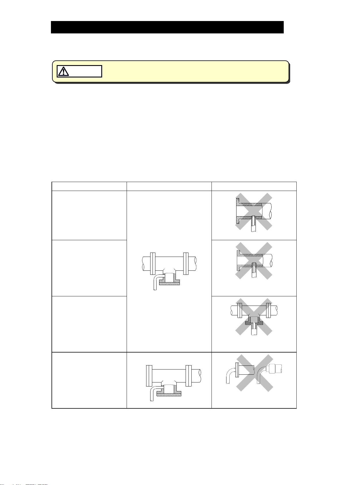
5. Has the piping work been done correctly, as shown in the figures below?
Requirement
Correct
Incorrect
Install catchpot with the
proper diameter.
Diameter is too small.
Make sure the flow of
condensate is not
obstructed.
Diameter is too small and inlet
protrudes into pipe interior.
To prevent rust and scale
from flowing into the trap,
the inlet pipe should be
connected 25 –50 mm (1
–2 in) above the base of
the T-pipe.
Rust and scale flow into the
trap with the condensate.
When installing on the
blind end, make sure the
flow of condensate is not
obstructed.
Condensate collects in the
pipe.
172-65591A-01 (P46UC-Y) 19 Jan 2021
4
Specifications
Install properly and DO NOT use this product outside the recommended
operating pressure, temperature and other specification ranges.
Improper use may result in such hazards as damage to the product or
malfunctions which may lead to serious accidents. Local regulations
may restrict the use of this product to below the conditions quoted.
CAUTION
Use only under conditions in which no freeze-up will occur. Freezing
may damage the product, leading to fluid discharge, which may cause
burns or other injury.
CAUTION
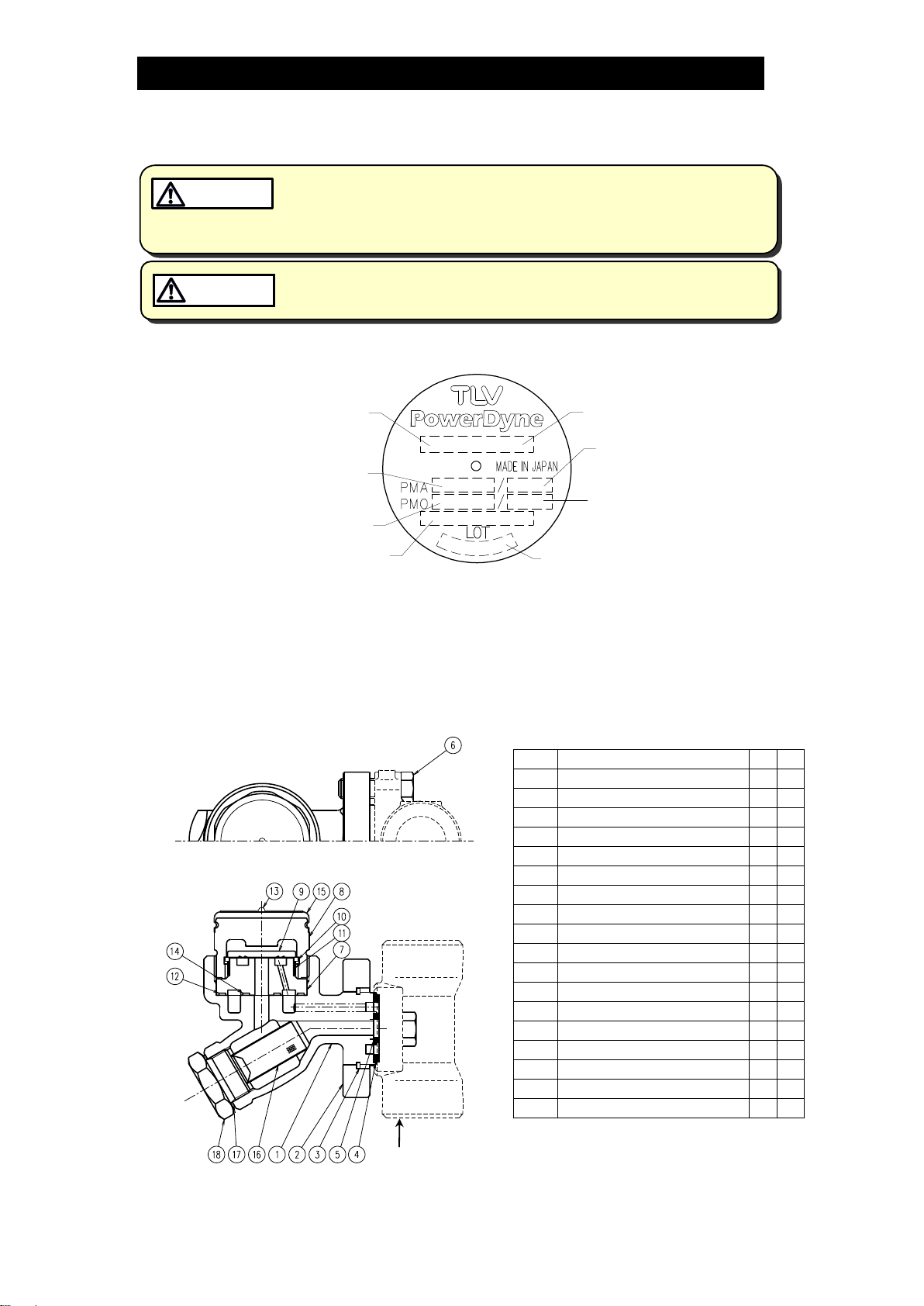
Refer to the product nameplate for detailed specifications.
Model
Production Lot No.
Maximum Allowable
Temperature (TMA)*
Maximum Operating
Temperature (TMO)
Nominal Diameter
Maximum Allowable
Pressure*
Maximum Operating
Pressure
Valve No.**
Minimum Operating Pressure: 0.03 MPaG (5 psig)
Maximum Allowable Back Pressure: 80% of the inlet pressure
* Maximum allowable pressure (PMA) and maximum allowable temperature (TMA) are
PRESSURE SHELL DESIGN CONDITIONS, NOT OPERATING CONDITIONS.
** Valve No. is displayed for products with options. This item is omitted from the nameplate
when there are no options.
Configuration
Connector body
without screen
No.
Name
M
R
1
Trap Body
2
Connector Flange
3
Snap Ring
4
Outer Connector Gasket
5
Inner Connector Gasket
6
Connector Bolt
7
Module Valve Seat
8
Cover
9
Disc
10
Disc Holder Ring
11
Air Vent Ring
12
Outer Module Gasket
13
Nameplate
14
Inner Module Gasket
15
Cap
16
Screen
17
Screen Holder Gasket
18
Screen Holder
*Replacement parts are available only in
the following kits:
M: Maintenance Kit
R: Repair Kit

172-65591A-01 (P46UC-Y) 19 Jan 2021
5
Installation
Install properly and DO NOT use this product outside the recommended
operating pressure, temperature and other specification ranges.
Improper use may result in such hazards as damage to the product or
malfunctions which may lead to serious accidents. Local regulations
may restrict the use of this product to below the conditions quoted.
CAUTION
Take measures to prevent people from coming into direct contact with
product outlets. Failure to do so may result in burns or other injury from
the discharge of fluids.
CAUTION
The installation procedures shown below are only for the P46UC-Y (trap unit). Please
follow the instruction manual provided by the manufacturer when installing the
connector unit itself.
Applicable connector units: Spirax Sarco PC10, Armstrong standard connector
(neither includes a screen)
(Installation, inspection, maintenance, repairs, disassembly, adjustment and valve
opening/closing should be carried out only by trained maintenance personnel.)
1. Install the product, onto the connector unit only if the connector unit is at ambient
temperature and there are no scratches or dirt on the seating surface of the gasket.
2. Before installation, be sure to remove all protective seals.
3. When installing the product onto the connector unit, the universal flange face (for
connecting to the trap unit) must be in the vertical plane, and the trap unit must be
installed with the nameplate facing upwards.
Refer to the “Detaching / Reattaching the Trap Unit”in the “Disassembly /
Reassembly”section described later in this manual.
4. Open the inlet and outlet valves and check to make sure that the product functions
properly.
If there is a problem, determine the cause using the “Troubleshooting” section in this
manual.
Installation Examples: Horizontal Piping
Correct
Incorrect
Nameplate is not facing
upwards
UniversalConnectorFlangeis not
inthe vertical plane
GroundGround
Nameplate
Connector
Flange
GroundGround
GroundGround
GroundGround
GroundGround
Installation Examples: Vertical Piping
Correct
Incorrect
Nameplate is not facing upwards
GroundGround
Nameplate
Connector
Flange
GroundGround
GroundGround
172-65591A-01 (P46UC-Y) 19 Jan 2021
6
Maintenance
Take measures to prevent people from coming into direct contact with
product outlets. Failure to do so may result in burns or other injury from
the discharge of fluids.
CAUTION
Be sure to use only the recommended components when repairing the
product, and NEVER attempt to modify the product in any way. Failure to
observe these precautions may result in damage to the product or burns
or other injury due to malfunction or the discharge of fluids.
CAUTION
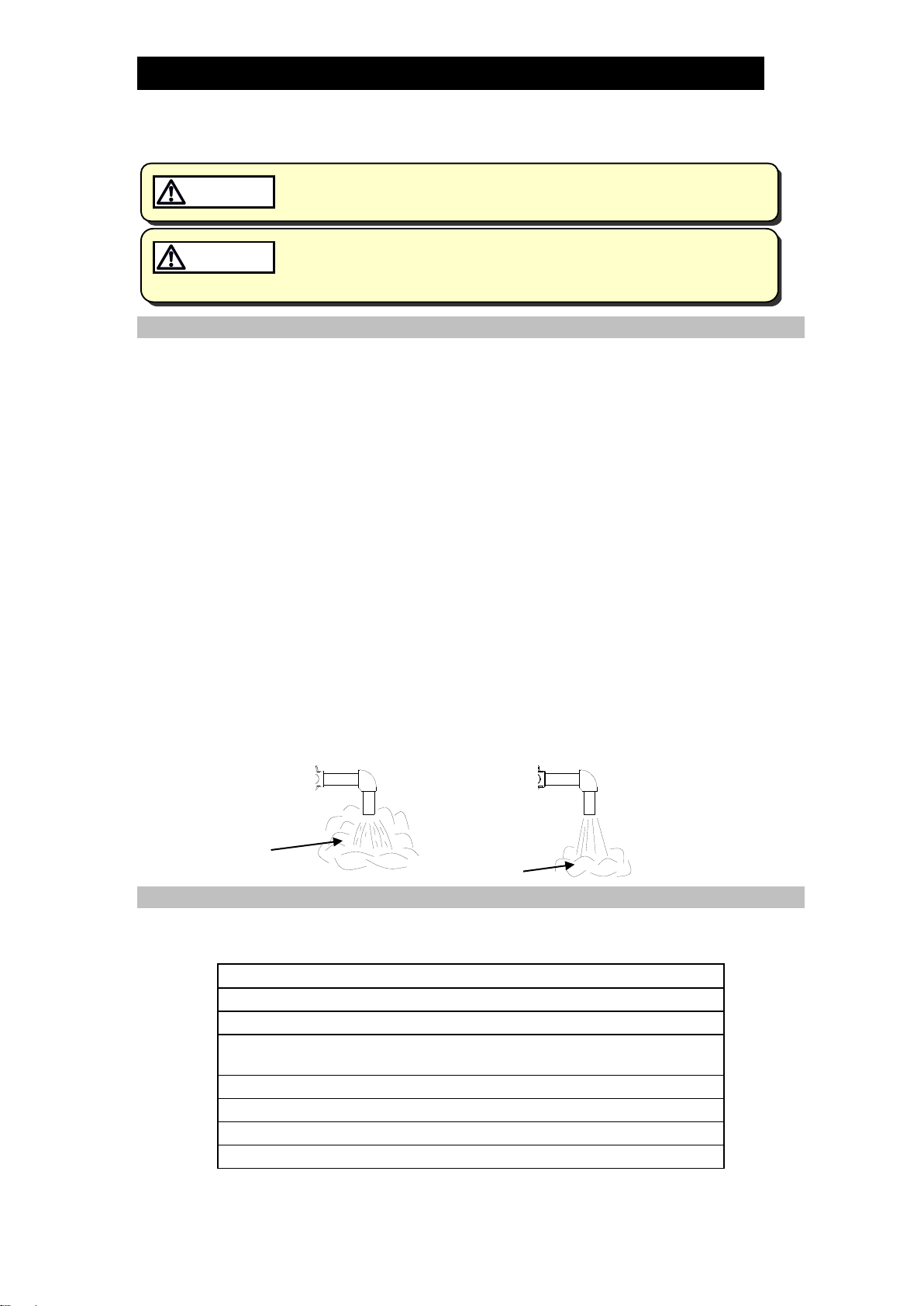
Operational Inspection
A visual inspection of the following items should be done on a daily basis to determine
whether the product is operating properly or has failed. Periodically (at least biannually)
the operation should also be checked by using diagnostic equipment such as a
stethoscope, thermometer, TLV Pocket TrapMan or TLV TrapMan.
If the product should fail, it may cause damage to piping and equipment, resulting in
faulty or low quality products or losses due to steam leakage.
Normal
:
Condensate is discharged continuously, together with flash steam,
and the sound of flow can be heard. If there is very little
condensate, there is almost no sound of flow.
Blocked
(Discharge Impossible)
:
No condensate is discharged. The product is quiet and makes no
noise, and the surface temperature of the product is low.
Blowing
:
Live steam continually flows from the outlet and there is a
continuous metallic sound.
Steam Leakage
:
Live steam is discharged through the trap outlet together with
condensate, accompanied by a high-pitched sound.
(When conducting a visual inspection, flash steam is sometimes mistaken for steam leakage. For this
reason, the use of a steam trap diagnostic instrument [such as TLV TrapMan if appropriate] in
conjunction with the visual inspection is highly recommended.)
Parts Inspection
When parts have been removed, or during periodic inspections, use the following table
to inspect the parts and replace any that are found to be defective.
Procedure
Gaskets:
Check for warping or scratches
Screens:
Check for clogging or corrosion
Disc:
Check for scratches or wear
Check dirt, oil film, wear and damage
Disc Holder Ring:
Check for scratches or wear
Air Vent Ring:
Check for scratches or wear
Module Valve Seat
Check for scratches or wear
Body Interior:
Check for build-up of scale
Flash Steam
Live Steam Leakage
Clear, slightly
bluish jet
White jet
containing
water droplets

172-65591A-01 (P46UC-Y) 19 Jan 2021
7
Disassembly/Reassembly
When disassembling or removing the product, wait until the internal
pressure equals atmospheric pressure and the surface of the product
has cooled to room temperature. Disassembling or removing the
product when it is hot or under pressure may lead to discharge of fluids,
causing burns, other injuries or damage.
CAUTION
The Disassembly/Reassembly procedures shown below are only for the P46UC-Y (trap
unit). Please follow the instruction manual provided by the manufacturer when
disassembling / assembling the connector unit itself.
Use the following procedures to remove the product and components. Use the same
procedures in reverse to reassemble.
(Installation, inspection, maintenance, repairs, disassembly, adjustment and valve
opening/closing should be carried out only by trained maintenance personnel.)
Detaching / Reattaching the Trap Unit
Part
During Disassembly
During Reassembly
Connector Bolts
Remove with a socket wrench
Consult the table of tightening torques
and tighten to the proper torque
Trap Unit
Remove the trap unit
Follow the special instructions below
(Fig. A)
Inner/Outer
Connector
Gaskets
Remove with a scraper and
clean the connector flange with a
soft tool
Replace with new gaskets; to facilitate
assembly and prevent loosening of the
gaskets, apply a small amount of
adhesive at 120º intervals around the
outer edge of the gaskets
Attaching the Trap Unit to the Connector Unit (Fig. A)
1. If attaching a new trap unit, be sure to remove the protective
cap from the connector flange. Be careful not to drop the
gaskets when removing the cap.
2. Grasp the end of the trap unit and align its gasket housing with
the indentation on the connector unit. Be sure to have the
nameplate facing upwards.
3. Once aligned, insert and finger tighten the connector bolts.
Verify that the trap unit is within the allowable inclination.
Figure A
Disassembly / Reassembly of Components (Screen) Inside the Trap Body
Part
During Disassembly
During Reassembly
Screen Holder
Remove with a socket wrench
Consult the table of tightening torques
and tighten to the proper torque
Screen Holder
Gasket
Remove the gasket
Replace with a new gasket only if warped
or damaged
Screen
Remove with needle-nose pliers
Insert securely into the trap body

172-65591A-01 (P46UC-Y) 19 Jan 2021
8
Removing / Reattaching of Components (Valve Seat Unit) Inside the Trap Body
Part
During Disassembly
During Reassembly
Figure B
Sealing
surface
Cover
Remove with a socket
wrench.
If the cover is seized do not
try to force it loose as this
could result in damage to
the piping. If the cover
appears to be seized,
loosen and remove the
connector bolts and
remove the entire trap unit
from the connector unit.
Then secure the trap unit in
a vice before attempting to
remove the cover.
Consult the table of
tightening torques and
tighten to the proper torque
Disc
Remove, being careful not
to scratch the lapped
surface
Make sure that the seat
surface (lapped side with
groove) is facing down,
toward the valve seat (Fig. B)
Disc Holder
Ring
Remove without bending
Set on the air vent ring and
make sure that it does not
sit on the valve seat surface
Air Vent Ring
Remove without bending,
as it will not return to its
proper shape
Reinsert without bending
Module Valve
Seat
Remove, being careful not
to scratch the lapped
surface
Insert into the body levelly,
being careful not to tilt it or
to scratch the seat surface
Outer Module
Gasket
Remove with a scraper and
clean the gasket housing
Replace with a new gasket
if misshapen or damaged
Inner Module
Gasket

172-65591A-01 (P46UC-Y) 19 Jan 2021
9
Table of Tightening Torques
Part Name
Torque
Distance Across Flats
Nm
(lbfft)
mm
(in)
Cover
250
(185)
46
(113/16)
Connector Bolt
39
(28)
14
(9/16)
Screen Holder
100
(73)
30
(13/16)
(1 Nm 10 kgcm)
NOTE:
- Coat all threaded portions with anti-seize.
- If drawings or other special documentation were supplied for the product, any torque
given there takes precedence over values shown here.
Exploded View
Nameplate
Cover
Disc
Disc Holder Ring
Air Vent Ring
Module Valve Seat
Inner Module Gasket
Outer Module Gasket
Trap Body
Screen Holder
Screen Holder Gasket
Screen
Connector Flange
Inner Connector Gasket
Outer Connector Gasket
(Connector Body)
Connector Bolt
Valve Seat Unit
Cap
172-65591A-01 (P46UC-Y) 19 Jan 2021
10
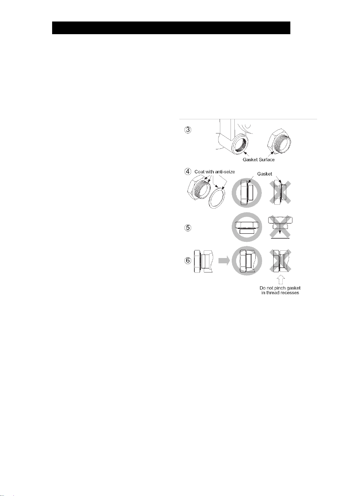
Instructions for Plug/Holder Disassembly and Reassembly
The seal on the threaded plugs/holders found on TLV products is formed by a flat metal
gasket. There are various installation orientations for the gaskets, such as horizontal,
diagonal and downward, and the gasket may be pinched in the thread recesses during
assembly.
Instructions for Disassembly and Reassembly
①Remove the plug/holder using a tool
of the specified size (distance across
flats).
②The gasket should not be reused. Be
sure to replace it with a new gasket.
③Clean the gasket surfaces of the
plug/holder and the product body
using a rag and/or cleaning agents,
then check to make sure the
surfaces are not scratched or
deformed.
④Coat both the gasket surface of the
plug/holder and the threads of the
plug/holder with anti-seize, then
press the gasket onto the center of
the gasket surface of the plug/holder,
making sure the anti-seize affixes
the gasket tightly to the plug/holder.
Check to make sure the gasket is
not caught in the recesses of the
threads.
⑤Hold the plug/holder upside down to
make sure that the anti-seize makes
the gasket stick to the plug/holder even when the plug/holder is held upside down.
⑥Screw the plug/holder by hand into the product body while making sure that the
gasket remains tightly affixed to the center of the gasket surface of the plug/holder.
Make sure the entire gasket is making contact with the gasket surface of the
product body. It is important at this point to make sure the gasket is not pinched in
the thread recesses of the plug/holder.
⑦Tighten the plug/holder to the proper torque.
⑧Next, begin the supply of steam and check to make sure there is no leakage from
the part just tightened. If there is leakage, immediately close the inlet valve and, if
there is a bypass valve, take the necessary steps to release any residual pressure.
After the surface of the product cools to room temperature, repeat the procedure
beginning from step 1.

172-65591A-01 (P46UC-Y) 19 Jan 2021
11
Troubleshooting
When disassembling or removing the product, wait until the internal
pressure equals atmospheric pressure and the surface of the product
has cooled to room temperature. Disassembling or removing the
product when it is hot or under pressure may lead to discharge of fluids,
causing burns, other injuries or damage.
CAUTION
If the trap fails to operate properly, use the following table to locate the cause and
remedy.
Problem
Cause
Remedy
No condensate is
discharged (blocked)
or discharge is poor
The module valve seat, screen or piping
are clogged with rust or scale
Clean parts
The disc is stuck to the module valve
seat surface
Clean parts
Air binding has occurred
Perform a bypass blowdown, or
close the trap inlet valve and
allow the trap to cool
Air binding due to the disc holder ring or
air vent ring wear
Replace with a new disc holder
ring or air vent ring
Steam-locking has occurred
Perform a bypass blowdown or
close the trap inlet valve and
allow the trap to cool. Piping
correction may also be required.
Trap operating pressure is below the
minimum specified pressure or there is
insufficient pressure differential between
the trap inlet and outlet
Compare specifications and
actual operating conditions
Steam is discharged
or leaks from the
outlet
(blowing)
(steam leakage)
Rust or scale on the disc or on the
module valve seat
Clean parts
Disc or module valve seat surface
damage or wear
Replace with a new disc
Replace with a new module
valve seat or trap unit
Improper installation orientation
Correct the installation
Trap vibration
Lengthen the inlet piping and
fasten it securely
Trap operating pressure is less than the
minimum specified pressure or the back
pressure exceeds the allowable back
pressure
Compare specifications and
actual operating conditions
The back pressure exceeds the
allowable back pressure (50% of inlet
pressure)
Compare specifications and
actual operating conditions
Steam is leaking from
a place other than the
outlet
Gasket deterioration or damage
Replace the gaskets
Improper tightening torque was used
Tighten to the proper torque
Note: If parts need replacement, refer to the parts list in this manual and select the appropriate
kit/unit for replacement parts. Parts are only available as a part of the kits/units shown.

172-65591A-01 (P46UC-Y) 19 Jan 2021
12
TLV EXPRESS LIMITED WARRANTY
Subject to the limitations set forth below, TLV Corporation, a North Carolina corporation
(“TLV”) warrants that products which are sold by it, TLV CO., LTD., a Japanese corporation
(“TLVJ”) or TLV International, Inc., a Japanese corporation (“TII”), (hereinafter the
“Products”) are designed and manufactured by TLVJ, conform to the specifications
published by TLV for the corresponding part numbers (the “Specifications”) and are free
from defective workmanship and materials. With regard to products or components
manufactured by unrelated third parties (the “Components”), TLV provides no warranty
other than the warranty from the third party manufacturer(s), if any.
Exceptions to Warranty
This warranty does not cover defects or failures caused by:
1. improper shipping, installation, use, handling, etc., by other than TLV or service
representatives authorized by TLV; or
2. dirt, scale or rust, etc.; or
3. improper disassembly and reassembly, or inadequate inspection and maintenance
by other than TLV or service representatives authorized by TLV; or
4. disasters or forces of nature or Acts of God; or
5. abuse, abnormal use, accidents or any other cause beyond the control of TLV; or
6. improper storage, maintenance or repair; or
7. operation of the Products not in accordance with instructions issued with the
Products or with accepted industry practices; or
8. use for a purpose or in a manner for which the Products were not intended; or
9. use of the Products in a manner inconsistent with the Specifications; or
10. use of the Products with Hazardous Fluids (fluids other than steam, air, water,
nitrogen, carbon dioxide and inert gases (helium, neon, argon, krypton, xenon and
radon)); or
11. failure to follow the instructions contained in the TLV Instruction Manual for the
Product.
Duration of Warranty
This warranty is effective for a period of the earlier of: (i) three (3) years after delivery of
Products to the first end user in the case of sealed SST-Series Products for use in steam
pressure service up to 650 psig; (ii) two (2) years after delivery of Products to the first end
user in the case of PowerTrap®units; or (iii) one (1) year after delivery of Products to the
first end user in the case of all other Products. Notwithstanding the foregoing, asserting a
claim under this warranty must be brought by the earlier of one of the foregoing periods,
as applicable, or within five (5) years after the date of delivery to the initial buyer if not
sold initially to the first end user.
ANY IMPLIED WARRANTIES NOT NEGATED HEREBY WHICH MAY ARISE BY OPERATION
OF LAW, INCLUDING THE IMPLIED WARRANTIES OF MERCHANTABILITY AND FITNESS
FOR A PARTICULAR PURPOSE AND ANY EXPRESS WARRANTIES NOT NEGATED HEREBY,
ARE GIVEN SOLELY TO THE INITIAL BUYER AND ARE LIMITED IN DURATION TO ONE (1)
YEAR FROM THE DATE OF SHIPMENT BY TLV.
Exclusive Remedy
THE EXCLUSIVE REMEDY UNDER THIS WARRANTY, UNDER ANY EXPRESS WARRANTY
OR UNDER ANY IMPLIED WARRANTIES NOT NEGATED HEREBY (INCLUDING THE IMPLIED
WARRANTIES OF MERCHANTABILITY AND FITNESS FOR A PARTICULAR PURPOSE), IS
REPLACEMENT; PROVIDED: (a) THE CLAIMED DEFECT IS REPORTED TO TLV IN WRITING
WITHIN THE APPLICABLE WARRANTY PERIOD, INCLUDING A DETAILED WRITTEN
DESCRIPTION OF THE CLAIMED DEFECT AND HOW AND WHEN THE CLAIMED DEFECTIVE
PRODUCT WAS USED; AND (b) THE CLAIMED DEFECTIVE PRODUCT AND A COPY OF THE

172-65591A-01 (P46UC-Y) 19 Jan 2021
13
PURCHASE INVOICE IS RETURNED TO TLV, FREIGHT AND TRANSPORTATION COSTS
PREPAID, UNDER A RETURN MATERIAL AUTHORIZATION AND TRACKING NUMBER
ISSUED BY TLV. ALL LABOR COSTS, SHIPPING COSTS, AND TRANSPORTATION COSTS
ASSOCIATED WITH THE RETURN OR REPLACEMENT OF THE CLAIMED DEFECTIVE
PRODUCT ARE SOLELY THE RESPONSIBILITY OF BUYER OR THE FIRST END USER. TLV
RESERVES THE RIGHT TO INSPECT ON THE FIRST END USER’S SITE ANY PRODUCTS
CLAIMED TO BE DEFECTIVE BEFORE ISSUING A RETURN MATERIAL AUTHORIZATION.
SHOULD SUCH INSPECTION REVEAL, IN TLV’S REASONABLE DISCRETION, THAT THE
CLAIMED DEFECT IS NOT COVERED BY THIS WARRANTY, THE PARTY ASSERTING THIS
WARRANTY SHALL PAY TLV FOR THE TIME AND EXPENSES RELATED TO SUCH ON-SITE
INSPECTION.
Exclusion of Consequential and Incidental Damages
IT IS SPECIFICALLY ACKNOWLEDGED THAT THIS WARRANTY, ANY OTHER EXPRESS
WARRANTY NOT NEGATED HEREBY, AND ANY IMPLIED WARRANTY NOT NEGATED
HEREBY, INCLUDING THE IMPLIED WARRANTIES OF MERCHANTABILITY AND FITNESS
FOR A PARTICULAR PURPOSE, DO NOT COVER, AND NEITHER TLV, TII NOR TLVJ WILL IN
ANY EVENT BE LIABLE FOR, INCIDENTAL OR CONSEQUENTIAL DAMAGES, INCLUDING,
BUT NOT LIMITED TO LOST PROFITS, THE COST OF DISASSEMBLY AND SHIPMENT OF
THE DEFECTIVE PRODUCT, INJURY TO OTHER PROPERTY, DAMAGE TO BUYER’S OR THE
FIRST END USER’S PRODUCT, DAMAGE TO BUYER’S OR THE FIRST END USER’S
PROCESSES, LOSS OF USE, OR OTHER COMMERCIAL LOSSES. WHERE, DUE TO
OPERATION OF LAW, CONSEQUENTIAL AND INCIDENTAL DAMAGES UNDER THIS
WARRANTY, UNDER ANY OTHER EXPRESS WARRANTY NOT NEGATED HEREBY OR
UNDER ANY IMPLIED WARRANTY NOT NEGATED HEREBY (INCLUDING THE IMPLIED
WARRANTIES OF MERCHANTABILITY AND FITNESS FOR A PARTICULAR PURPOSE)
CANNOT BE EXCLUDED, SUCH DAMAGES ARE EXPRESSLY LIMITED IN AMOUNT TO THE
PURCHASE PRICE OF THE DEFECTIVE PRODUCT. THIS EXCLUSION OF CONSEQUENTIAL
AND INCIDENTAL DAMAGES, AND THE PROVISION OF THIS WARRANTY LIMITING
REMEDIES HEREUNDER TO REPLACEMENT, ARE INDEPENDENT PROVISIONS, AND ANY
DETERMINATION THAT THE LIMITATION OF REMEDIES FAILS OF ITS ESSENTIAL
PURPOSE OR ANY OTHER DETERMINATION THAT EITHER OF THE ABOVE REMEDIES IS
UNENFORCEABLE, SHALL NOT BE CONSTRUED TO MAKE THE OTHER PROVISIONS
UNENFORCEABLE.
Exclusion of Other Warranties
THIS WARRANTY IS IN LIEU OF ALL OTHER WARRANTIES, EXPRESS OR IMPLIED, AND
ALL OTHER WARRANTIES, INCLUDING BUT NOT LIMITED TO THE IMPLIED WARRANTIES
OF MERCHANTABILITY AND FITNESS FOR A PARTICULAR PURPOSE, ARE EXPRESSLY
DISCLAIMED.
Severability
Any provision of this warranty which is invalid, prohibited or unenforceable in any
jurisdiction shall, as to such jurisdiction, be ineffective to the extent of such invalidity,
prohibition or unenforceability without invalidating the remaining provisions hereof, and
any such invalidity, prohibition or unenforceability in any such jurisdiction shall not
invalidate or render unenforceable such provision in any other jurisdiction.
13901 South Lakes Drive, Charlotte, NC 28273-6790, U.S.A.
Tel: [1]-704-597-9070 Fax: [1]-704-583-1610

172-65591A-01 (P46UC-Y) 19 Jan 2021
14
Options
When operating the blowdown valve, stand to the side well clear of the
outlet to avoid contact with internal fluids that will be discharged. Failure
to do so may result in burns or other injury.
CAUTION
Do not use excessive force when opening the blowdown valve. Such
force may break the pin equipped as a valve stopper pin, causing a
blowout from internal pressure resulting in burns or other injury.
CAUTION
With Blowdown Valve (TLV BD2)
Configuration
Screen Holder Gasket
BD2 Valve Seat
(Screen Holder)
BD2 Valve
Discharge Hole
Screen
Stopper Pin
TLV Blowdown Valve: BD2
The BD2 Blowdown Valve, installed in the screen area of the trap body, uses the trap’s
internal pressure to blow any condensate, steam, dirt or scale accumulated around the
screen area out to atmosphere.

172-65591A-01 (P46UC-Y) 19 Jan 2021
15
BD2 Blowdown Valve Operation
Install properly and DO NOT use this product outside the recommended
operating pressure, temperature and other specification ranges.
Improper use may result in such hazards as damage to the product or
malfunctions which may lead to serious accidents. Local regulations
may restrict the use of this product to below the conditions quoted.
CAUTION
Take measures to prevent people from coming into direct contact with
product outlets. Failure to do so may result in burns or other injury from
the discharge of fluids.
CAUTION
Do not use excessive force when connecting threaded pipes to the
product. Over-tightening may cause breakage leading to fluid
discharge, which may cause burns or other injury.
CAUTION
1. The BD2 valve is in the closed position when the BD2 is shipped from the factory.
Before attempting to operate the BD2, reconfirm that the BD2 valve is still in the
closed position. Locate the blow outlet and, during operation, stand to the side and
well clear of it, as the jet of condensate or steam could cause burns.
2. Remain in the area the entire time the BD2 valve is in the open position. Before
opening the BD2 valve, grip the BD2 valve seat with a wrench and hold firmly in
place so that it will not rotate when the BD2 valve is loosened. Grip the BD2 valve
with another wrench and slowly loosen. Condensate and steam will discharge from
the blow outlet in a jet stream. Be careful not to loosen the BD2 valve so far that it
becomes removed from the BD2 valve seat. (If the grooved pin becomes damaged,
large quantities of steam will be discharged in a jet stream.)
3. Close the BD2 valve until the flow of fluid completely stops. If the flow of fluid does
not stop, re-open the valve (as in step “2”) to blow out any scale or dirt that may be
caught in the valve. Re-tighten the valve until the flow of fluid stops completely.
Tightening Torques and Distance Across Flats
Part Name
Torque
Distance Across Flats
Nm
(lbfft)
mm
(in)
BD2 Valve
30
(22)
17
(21/32)
Screen Holder
100
(73)
30
(13/16)
(1 Nm 10 kgcm)
NOTE: Avoid the use of excessive tightening torques, as threaded parts may become damaged.
Table of contents
Other TLV Industrial Equipment manuals


Popular Industrial Equipment manuals by other brands

EASTMAN
EASTMAN C Series Instruction and Illustrated manual

Yale
Yale MWW Series operating instructions

Wow
Wow Coolius 4000 Bus instruction manual

PCB Piezotronics
PCB Piezotronics PCB Load & Torque 1102-03A Installation and operating manual

Indutherm
Indutherm VTC Series instruction manual

Speedball
Speedball 004230 manual


