TLV SW1U-A User manual
172-65288MA-02 (SW1U-A/SW1U-B) 6 February 2019
Process Lever Float Steam Trap
SW1U-A / SW1U-B
Copyright © 2019 by TLV CO., LTD.
All rights reserved

172-65288MA-02 (SW1U-A/SW1U-B) 6 Feb 2019
1
Contents
Introduction .......................................................................2
Safety Considerations.......................................................3
Checking the Piping..........................................................5
Operation ..........................................................................5
Specifications....................................................................6
Configuration.....................................................................7
Installation.........................................................................8
Maintenance....................................................................10
Disassembly/Reassembly...............................................11
Troubleshooting ..............................................................12
Product Warranty ............................................................13
172-65288MA-02 (SW1U-A/SW1U-B) 6 Feb 2019
2
Introduction
Thank you for purchasing the TLV process lever float steam trap.
This product has been thoroughly inspected before being shipped from the factory.
When the product is delivered, before doing anything else, check the specifications
and external appearance to make sure nothing is out of the ordinary. Also be sure to
read this manual carefully before use and follow the instructions to be sure of using
the product properly.
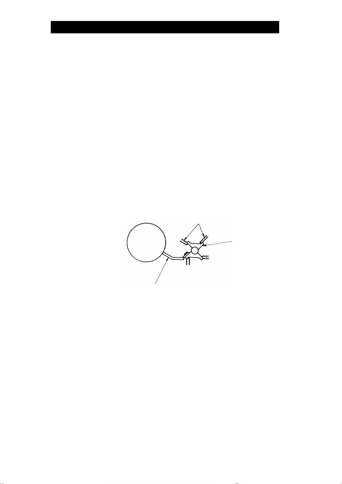
This steam trap employs TLY®(Tetra-Leaf & Yoke) construction, which affords it
stable operation and long service life. TLY construction was developed for process
lever float steam traps, and comprises a four-bladed valve connected directly to a
lever float.
As the valve opening and closing forces created by the pressure differential
between inlet and outlet pressures are balanced, a four-bladed valve ensures stable
trap operation at all times.
This trap is ideal for applications requiring the removal of condensate from
equipment using large quantities of steam and from process machinery.
Additionally, it quickly and automatically discharges large quantities of condensate
at a temperature slightly lower than saturation temperature.
For products with special order specifications or options, if detailed instructions for
the special order specifications or options are not contained in this manual, please
contact TLV for full details.
This instruction manual is intended for use with the model(s) listed on the front
cover. It is necessary not only for installation but for subsequent maintenance,
disassembly/reassembly and troubleshooting. Please keep it in a safe place for
future reference.
TLY is a registered trademark of TLV CO., LTD.
Valve Seat
Four-bladed
Valve
Lever Float

172-65288MA-02 (SW1U-A/SW1U-B) 6 Feb 2019
3
Safety Considerations
•Read this section carefully before use and be sure to follow the instructions.
•Installation, inspection, maintenance, repairs, disassembly, adjustment,
and valve opening/closing should be carried out only by trained
maintenance personnel.
•The precautions listed in this manual are designed to ensure safety and
prevent equipment damage and personal injury. For situations that may
occur as a result of erroneous handling, three different types of cautionary
items are used to indicate the degree of urgency and the scale of potential
damage and danger: DANGER, WARNING and CAUTION.
•The three types of cautionary items above are very important for safety:
be sure to observe all of them as they relate to installation, use,
maintenance, and repair. Furthermore, TLV accepts no responsibility for
any accidents or damage occurring as a result of failure to observe these
precautions.
Symbols
Indicates a DANGER, WARNING or CAUTION item.
DANGER
Indicates an urgent situation which poses a threat of death or
serious injury
WARNING
Indicates that there is a potential threat of death or serious injury
CAUTION
Indicates that there is a possibility of injury or equipment / product
damage
WARNING
NEVER apply direct heat to the float.
The float may explode due to increased internal pressure, causing
accidents leading to serious injury or damage to property and
equipment.
CAUTION
Install properly and DO NOT use this product outside the
recommended operating pressure, temperature and other
specification ranges.
Improper use may result in such hazards as damage to the
product or malfunctions that may lead to serious accidents. Local
regulations may restrict the use of this product to below the
conditions quoted.
DO NOT use this product in excess of the maximum
operating pressure differential.
Such use could make discharge impossible (blocked).
Use hoisting equipment for heavy objects (weighing
approximately 20 kg (44 lb) or more).
Failure to do so may result in back strain or other injury if the
object should fall.
Continued on the next page

172-65288MA-02 (SW1U-A/SW1U-B) 6 Feb 2019
4
CAUTION
Take measures to prevent people from coming into direct
contact with product outlets.
Failure to do so may result in burns or other injury from the
discharge of fluids.
When disassembling or removing the product, wait until the
internal pressure equals atmospheric pressure and the
surface of the product has cooled to room temperature.
Disassembling or removing the product when it is hot or under
pressure may lead to discharge of fluids, causing burns, other
injuries or damage.
Be sure to use only the recommended components when
repairing the product, and NEVER attempt to modify the
product in any way.
Failure to observe these precautions may result in damage to the
product and burns or other injury due to malfunction or the
discharge of fluids.
Use only under conditions in which no freeze-up will occur.
Freezing may damage the product, leading to fluid discharge,
which may cause burns or other injury.
Use only under conditions in which no water hammer will
occur.
The impact of water hammer may damage the product, leading to
fluid discharge, which may cause burns or other injury.
172-65288MA-02 (SW1U-A/SW1U-B) 6 Feb 2019
5
Checking the Piping
Use only under conditions in which no water hammer will occur. The
impact of water hammer may damage the product, leading to fluid
discharge, which may cause burns or other injury.
CAUTION
Check to make sure that the pipes to be connected to the trap have been installed
properly.
1. Is the pipe diameter suitable?
2. Is the piping where the trap is to be installed horizontal?
3. Has sufficient space been secured for maintenance?
4. Have isolation valves been installed at the inlet and outlet? If the outlet is subject
to back pressure, has a check valve been installed?
5. Has a bypass line been installed properly?
6. Is the inlet pipe as short as possible, with as few bends as possible, and installed
so the liquid will flow naturally down into the trap?
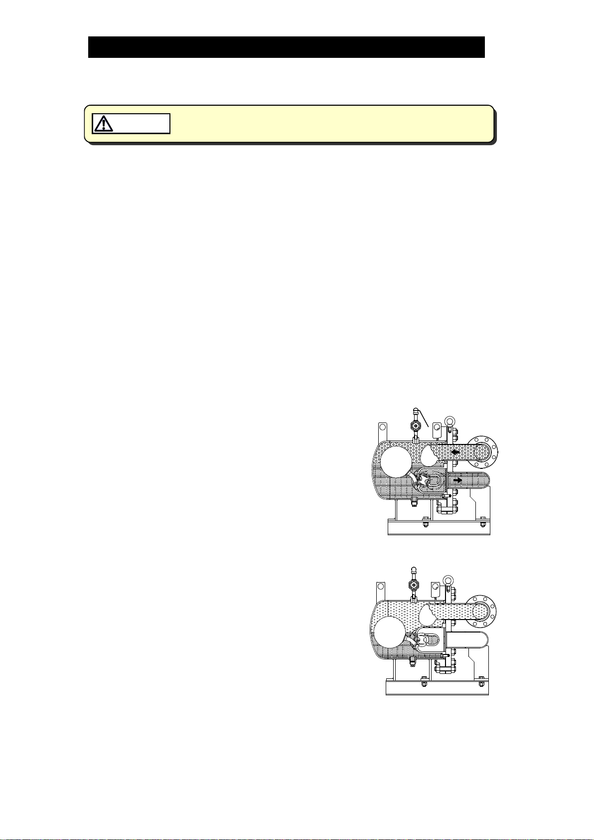
Operation
Principles of condensate discharge:
At start-up, open the bypass valve to remove any initial
condensate or air at 100°C (212°F) or less.
(This step must be performed in order to ensure
smooth start-up.)
Air binding occurs when the inflow of steam is
accompanied by the inflow of air during normal
operation. Whenever air binding occurs, it can be
released by opening the bellows sealed valve to
discharge the air.
After air is discharged, the bellows sealed valve must
be closed.
As condensate flows into the trap, the rising
condensate level causes the float to rise due to
buoyancy, automatically opening the valve and
allowing condensate to be continuously discharged.
When this occurs, the opening size of the valve varies
depending on the condensate flow rate.
As the condensate is discharged, the condensate level
falls, causing the float to fall, thereby automatically
closing the valve.
The valve remains closed as long as no condensate
enters the trap.
Bellows Sealed
Valve

172-65288MA-02 (SW1U-A/SW1U-B) 6 Feb 2019
6
Specifications
Install properly and DO NOT use this product outside the recommended
operating pressure, temperature and other specification ranges.
Improper use may result in such hazards as damage to the product or
malfunctions which may lead to serious accidents. Local regulations
may restrict the use of this product to below the conditions quoted.
CAUTION
DO NOT use this product in excess of the maximum operating pressure
differential; such use could make discharge impossible (blocked).
CAUTION
Use only under conditions in which no freeze-up will occur. Freezing
may damage the product, leading to fluid discharge, which may cause
burns or other injury.
CAUTION
Refer to the product nameplate for detailed specifications.
Maximum Allowable
Temperature (TMA)
Model
Valve No.*
Maximum Operating
Pressure Maximum Differential
Pressure
Production Lot No.
Nominal Diameter
* Valve No. is displayed for products with options. This item is omitted from the nameplate
when there are no options.
172-65288MA-02 (SW1U-A/SW1U-B) 6 Feb 2019
7
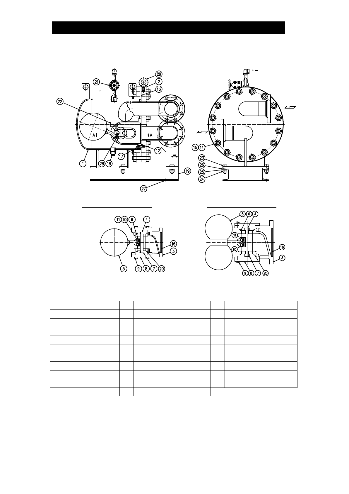
Configuration
No.
Name
No.
Name
No.
Name
1
Body Unit
11
Spring Washer
21
Bellows Sealed Valve
2
Cover Unit
12
Valve Seat Body Gasket
22
Nameplate
3
Valve Seat Body
13
Cover Gasket
23
Mounting Bolt
4
TLY Valve
14
Cover Bolt
24
Mounting Nut
5
Float Unit
15
Cover Nut
25
Spring Washer
6
Seal Ring
16
Baffle
26
Washer
7
Bearing
17
Valve Seat Body Bolt
27
Foundation Bolt
8
Valve Holder
18
Drain Plug
28
Set Screw
9
Valve Holder Bolt
19
Mounting Base
29
Eye Bolt
10
Lever Bolt
20
Wave Spring
A-A Cut View (SW1U-A) A-A Cut View (SW1U-B)
172-65288MA-02 (SW1U-A/SW1U-B) 6 Feb 2019
8
Installation
Install properly and DO NOT use this product outside the recommended
operating pressure, temperature and other specification ranges.
Improper use may result in such hazards as damage to the product or
malfunctions which may lead to serious accidents. Local regulations
may restrict the use of this product to below the conditions quoted.
CAUTION
Use hoisting equipment for heavy objects (weighing approximately
20 kg (44 lb) or more). Failure to do so may result in back strain or other
injury if the object should fall.
CAUTION
Take measures to prevent people from coming into direct contact with
product outlets. Failure to do so may result in burns or other injury from
the discharge of fluids.
CAUTION
Installation, inspection, maintenance, repairs, disassembly, adjustment and valve
opening/closing should be carried out only by trained maintenance personnel.
1. Before installation, be sure to remove all protective seals.
2. When installing the product, be sure to install a bypass line. At start-up, open
the bypass valve to remove initial condensate and air of less than 100°C
(212°F).
3. Install an inlet valve and strainer at the trap inlet.
4. Before installing the product, open the inlet valve and blow out the piping to
remove any piping scraps, dirt and oil. Close the inlet valve after blowdown.
5. Install an outlet pipe with consideration for maintenance work from the bellows
sealed valve for the discharge of air safely to a drainage vessel or ditch.
Make sure the end of the pipe is above the waterline, so that dirt and water
cannot be sucked up by vacuum when the system shuts down and the bellows
sealed valve is open.
6. Secure the product to the mounting base using the 4 foundation bolts.
7. A shut-off valve should be installed at the product outlet.
8. Install the product so the arrow on the body is pointing in the direction of
condensate flow.
9. Install the product into the piping in a manner that lets the condensate flow
naturally down into the trap.
10. Secure the necessary space to perform a complete disassembly and inspection.
(See the figures on the next page.)
If there is a problem, determine the cause using the “Troubleshooting” section in this
manual.

172-65288MA-02 (SW1U-A/SW1U-B) 6 Feb 2019
9
SW1U-A
SW1U-B
(Units: mm (in) )
(415/16)
(493/
16
)
(77/8)
(97/8)
(63)
(531/
8
)
Install outlet pipe for air
discharge to the safe place

172-65288MA-02 (SW1U-A/SW1U-B) 6 Feb 2019
10
Maintenance
Take measures to prevent people from coming into direct contact with
product outlets. Failure to do so may result in burns or other injury from
the discharge of fluids.
CAUTION
Be sure to use only the recommended components when repairing the
product, and NEVER attempt to modify the product in any way. Failure to
observe these precautions may result in damage to the product or burns
or other injury due to malfunction or the discharge of fluids.
CAUTION
Operational Check
A visual inspection of the following items should be done on a daily basis to
determine whether the product is operating properly or has failed. Periodically (at
least once every six months) the operation should also be checked by using
diagnostic equipment, such as a stethoscope or thermometer. A complete
disassembly and inspection should be performed at least once every 3 years.
If the product should fail, it may cause damage to piping and equipment, resulting in
faulty or low quality products or losses due to steam leakage.
Normal
:
Condensate is discharged continuously, together with flash
steam, and the sound of flow can be heard. If there is very little
condensate, there is almost no sound of flow.
Blocked
(Discharge
Impossible)
:
No condensate is discharged. The trap is quiet and makes no
noise, and the surface temperature of the trap is low.
Blowing
:
Live steam continually flows from the outlet and there is a
continuous metallic sound.
Steam Leakage :
Live steam is discharged through the trap outlet together with
condensate, accompanied by a high-pitched sound.
NOTE:
Flash steam: White jet containing water droplets
Live steam: Clear, slightly bluish jet
Parts Inspection
When parts have been removed, or during periodic inspections, use the following
table to inspect the parts and replace any that are found to be defective.
Procedure
Gaskets: Check for damage and warping
Float: Check for breakage, deformation and water on the inside
Seal Ring, Bearing: Check for breakage and wear
Valve, Valve Seat Body: Check for dirt build-up, damage and deformation

172-65288MA-02 (SW1U-A/SW1U-B) 6 Feb 2019
11
Disassembly/Reassembly
NEVER apply direct heat to the float. The float may explode due to
increased internal pressure, causing accidents leading to serious injury
or damage to property and equipment.
WARNING
Use hoisting equipment for heavy objects (weighing approximately
20 kg (44 lb) or more). Failure to do so may result in back strain or other
injury if the object should fall.
CAUTION
When disassembling or removing the product, wait until the internal
pressure equals atmospheric pressure and the surface of the product
has cooled to room temperature. Disassembling or removing the
product when it is hot or under pressure may lead to discharge of fluids,
causing burns, other injuries or damage.
CAUTION
Use the following procedures to remove components. Use the same procedures in
reverse to reassemble. (Installation, inspection, maintenance, repairs, disassembly,
adjustment and valve opening/closing should be carried out only by trained
maintenance personnel.)
Disassembly/Reassembly
Part
During Disassembly
During Reassembly
Bellows
Sealed Valve
Slowly open before
disassembling the trap and make
sure no remained pressure in the
trap
Close after reassembling the trap
Body Unit
Loosen and remove the cover
nuts and bolts connecting the
body unit and cover unit
Consult the table of tightening torques and
tighten cover nuts to the proper torque
Cover Gasket
Remove the gasket and clean
sealing surfaces
Replace with a new gasket
Valve Seat
Body
Loosen the valve seat body bolts
and remove from the cover unit
Consult the table of tightening torques and
tighten valve seat body bolts to the proper
torque
Valve Seat
Body Gasket
Remove the gasket and clean
sealing surfaces
Replace with a new gasket if warped or
damaged
Float Unit
Remove the lever bolts, then
remove from the valve
Consult the table of tightening torques and
tighten lever bolts to the proper torque;
TLY Valve
Remove the valve holder bolts
from the valve seat body, remove
the valve holder and then remove
the TLY valve
Consult the table of tightening torques and
tighten flange bolts to the proper torque
Seal Ring,
Bearing
Remove from the valve seat body
Replace with new rings if warped or
damaged

172-65288MA-02 (SW1U-A/SW1U-B) 6 Feb 2019
12
Table of Tightening Torques
Part
SW1U-A
SW1U-B
Torque
Distance Across
Flats
Torque
Distance Across
Flats
N⋅m
(lbf·ft)
mm
(in)
N⋅m
(lbf·ft)
mm
(in)
Cover Nut
300
(220)
30
(13/16)
1,200
(890)
46
(113/16)
Valve Seat
Body Bolt
100 (73) 24 (15/16) 350 (260) 30 (13/16)
Valve
Holder Bolt
100 (73) 24 (15/16) 120 (88) 24 (15/16)
Lever Bolt
35
(26)
16
(5/8)
150
(110)
24
(15/16)
NOTE:
-Coat all threaded portions with anti-seize.
-If drawings or other special documentation were supplied for the
product, any torque given there takes precedence over values
shown here.
(1 N⋅m ≈10 kg⋅cm
)
Troubleshooting
NEVER apply direct heat to the float. The float may explode due to
increased internal pressure, causing accidents leading to serious injury
or damage to property and equipment.
WARNING
When disassembling or removing the product, wait until the internal
pressure equals atmospheric pressure and the surface of the product
has cooled to room temperature. Disassembling or removing the
product when it is hot or under pressure may lead to discharge of fluids,
causing burns, other injuries or damage.
CAUTION
When the product fails to operate properly, use the following table to locate and
cause the remedy.
Problem
Cause
Remedy
No condensate
is discharged
The float is damaged or filled with
condensate
Replace with a new float unit
The valve is stuck closed
Disassemble, inspect, clean
The inlet strainer has become clogged
Clean the strainer
Condensate
discharge is
poor
The inlet pressure is too small or the
back pressure is too large
Adjust the pressure
The inlet strainer has become clogged
Clean the strainer
Steam is
blowing
The valve or valve seat body have a
build-up of dirt
Disassemble, inspect, clean
The valve or valve seat body are
damaged or deformed
Replace with a new valve
and/or valve seat body
The valve is stuck closed
Disassemble, inspect, clean

172-65288MA-02 (SW1U-A/SW1U-B) 6 Feb 2019
13
Product Warranty
1. Warranty Period
One year following product delivery.
2. Warranty Coverage
TLV CO., LTD. warrants this product to the original purchaser to be free
from defective materials and workmanship. Under this warranty, the
product will be repaired or replaced at our option, without charge for parts
or labor.
3. This product warranty will not apply to cosmetic defects, nor to any
product whose exterior has been damaged or defaced; nor does it apply
in the following cases:
1) Malfunctions due to improper installation, use, handling, etc., by other
than TLV CO., LTD. authorized service representatives.
2) Malfunctions due to dirt, scale, rust, etc.
3) Malfunctions due to improper disassembly and reassembly, or
inadequate inspection and maintenance by other than TLV CO., LTD.
authorized service representatives.
4) Malfunctions due to disasters or forces of nature.
5) Accidents or malfunctions due to any other cause beyond the control
of TLV CO., LTD.
4. Under no circumstances will TLV CO., LTD. be liable for consequential
economic loss damage or consequential damage to property.
* * * * * * *
For Service or Technical Assistance:
Contact your TLV representative or your regional TLV office.
Manufacturer
881 Nagasuna, Noguchi
Kakogawa, Hyogo 675-8511, JAPAN
Tel: 81-(0)79-427-1800
This manual suits for next models
1
Table of contents
Other TLV Industrial Equipment manuals


