Forma Scientific 1184 User manual

Covers Models:
1184/1186, 1185, 1194/1196
Biological Safety Cabinet
Class Ii, Type A/B3
Manual 7001186
IMPORTANT: READ THIS TECHNICAL MANUAL CAREFULLY TO DETERMINE
PROPER INSTALLATION, OPERATION, AND USAGE PROCEDURES. PAY CAREFUL
ATTENTION TO ALL CAUTIONS AND WARNINGS.
CAUTION: ALL INTERNAL ADJUSTMENTS AND MAINTENANCE MUST BE
PERFORMED BY QUALIFIED SERVICE PERSONNEL.
March 1992

INDEX
PAGE
SECTION 1 – RECEIVING 4
1.1 Preliminary Inspection 5
1.2 Visible Loss or Damage 5
1.3 Concealed Loss or Damage 5
1.4 Responsibility for Shipping Damage 5
1.5 Unpacking List 5
SECTION 2 - INTRODUCTION 6
2.1 Description 7
2.2 Theory of Operation 7
2.3 Airflow Diagram (Fig. 2.0) 8
SECTION 3 - INSTALLATION OF CABINET 9
3.1 Location 10
3.2 Power Connection 10
3.3 Plumbing Connection 10
3.4 Exhaust Requirements 11
2

INDEX (continued)
PAGE
SECTION 4 - OPERATION OF CABINET 12
4.1 Control & Indicating Devices 13
A) Blower Switch 13
B) Light Switch 13
C) Ultra-Violet Light (Optional) 13
D) Alarm By-Pass Switch
(sliding window models only) 13
E) Static Pressure Gauge (in. w.g.) 14
F) Blower Speed Control 14
G) Blower Motor/Lights Reset Button (15 Amp) 14
H) Receptacle Reset Button (15 Amp) 15
I) Duplex Receptacles 15
J) Drain Valve 15
K) Service Valves 16
L) Exhaust Filter Guard 16
M) Hinged Window Assembly 16
N) Sliding Window Assembly 16
4.2 Overview of Cabinet Dwg 4.0 17
4.3 Overview of Control Panel Dwg. 4.1 (Model 1184/1186) 18
4.4 Overview of Control Panel Dwg. 4.2 (Model 1194/1196) 19
SECTION 5 - GENERAL CAUTIONS 20
5.1 General Caution Notes 21
5.2 Important Label Location Drawing 22
SECTION 6 - CABINET START-UP 23
6.1 General Recommendations 24
6.2 Use of Auxiliary Equipment in the Cabinet 24
6.3 Cabinet Check 25
6.4 Start-Up Procedure 25
SECTION 7 - TROUBLESHOOTING 26
7.1 Troubleshooting Guide 27-28
3

INDEX (continued)
PAGE
SECTION 8 - MAINTENANCE 29
8.1 Checking the Static Pressure Gauge "Zero" 30
8.2 Re-zeroing the Static Pressure Gauge 30
8.3 Adjusting the Damper 30-31
8.4 BSC Test Grids (Model 1184/1186) 32
8.5 BSC Test Grids (Model 1186/1196) 33
SECTION 9 - SPECIFICATIONS 34
9.1 Model 1184 (4' Cabinet with sliding window) 35
9.2 Model 1185 (4’ Cabinet with sliding window) 36
9.2 Model 1186 (6' Cabinet with sliding window) 37
9.3 Model 1194 (4' Cabinet with hinged window) 38
9.4 Model 1196 (6' Cabinet with hinged window) 39
SECTION 10 - ACCESSORIES 40
10.1 Accessories (Chart) 41
SECTION 11 - REPLACEMENT PARTS 42
11.1 Model 1184/1185 Replacement Parts 43
11.2 Model 1186 Replacement Parts 44
11.3 Model 1194 Replacement Parts 45
11.4 Model 1196 Replacement Parts 46
SUPPLEMENTS 47
4

SECTION 1 - RECEIVING
Table of Contents
1.1 Preliminary Inspection
1.2 Visible Loss or Damage
1.3 Concealed Loss or Damage
1.4 Responsibility for Shipping Damage
1.5 Unpacking List
5

1.1 PRELIMINARY INSPECTION
This item was thoroughly inspected and carefully packed prior to shipment and all necessary
precautions were taken to ensure safe arrival of the merchandise at its destination. Immediately
upon receipt, before the unit is moved from the receiving area, carefully examine the shipment for
loss or damage. Unpack the shipment and inspect both interior and exterior for any in-transit
damage.
1.2 VISIBLE LOSS OR DAMAGE
If any loss or damage is discovered, note any discrepancies on the delivery receipt. Failure to
adequately describe such evidence of loss or damage may result in the carrier refusing to honor a
damage claim. Immediately call the delivering carrier and request that their representative perform
an inspection. Do not discard any of the packing material and under no circumstances move the
shipment from the receiving area.
1.3 CONCEALED LOSS OR DAMAGE
If damage is discovered upon unpacking the shipment, stop further unpacking, retain all packaging
material and immediately notify the delivering carrier, requesting that an inspection be performed
as soon as possible. Again, under no circumstances move the shipment from the receiving area.
1.4 RESPONSIBILITY FOR SHIPPING DAMAGE
For products shipped F.O.B. Marietta, Ohio, the responsibility of Forma Scientific, Inc. ends when
the merchandise is loaded onto the carrier's vehicle.
On F.O.B. Destination shipments, Forma Scientific's and the carrier's responsibility ends when your
Receiving Department personnel sign a free and clear delivery receipt.
Whenever possible, Forma Scientific, Inc. will assist in settling claims for loss or in-transit damage.
1.5 UNPACKING LIST
The "Installation/Operation" manual is taped down to the interior work chamber of the cabinet.
Included with the Installation/Operation manual are four index buttons. These buttons may be used
to identify the type of service supplied to the service valves. Also included in a separate bag, is a
small Allen wrench (used for calibrating the Static Pressure Gauge). This Allen wrench should be
kept with the manual at all times.
6

SECTION 2 - INTRODUCTION
Table of Contents
2.1 Description
2.2 Theory of Operation
2.3 Airflow Diagram (Fig. 2.0)
7

2.1 DESCRIPTION
The Model 1184/1186/1194/1196 Series is a Class II, Type A/B3 cabinet. The "Type A/B3"
designation indicates two alternative uses of the cabinet. When vented directly into the laboratory
room, the unit serves a "Type A" unit. When vented to the outside atmosphere, through an in-house
exhaust system, it serves as a "Type B3" unit. Either usage of the cabinet offers both personnel and
product protection.
The cabinet can be used with low-to-moderate risk hazard to the user and/or the experiment. Class
1, 2, and 3 (low-to-moderate risk) agents are described in the "BIOSAFETY IN
MICROBIOLOGICAL AND BIOMEDICAL LABORATORIES"; CDC NIH Publication No.
(NIH) 88-8395, 2nd Edition, May 1988. The Model 1184/1186/1194/1196 cabinets are designed to
meet the requirements of the National Sanitation Foundation Standard #49.
The cabinet is available in a sliding or hinged window version. The cabinet's window permits the
user to place auxiliary equipment and research implements in the work area. The work opening
must be held to 10" during all work procedures. If the window is raised higher than the designated
10", the air barrier at the front of the cabinet will be weakened and containment will be seriously
impaired.
2.2 THEORY OF OPERATION
Figure 2.0 on the following page shows the general airflow pattern of the cabinet.
Clean HEPA filtered air descends through the work zone with approximately 40% being discharged
through the exhaust HEPA filter with the remaining air recirculating through the supply HEPA
filter into the work area. Exhausted air must be replaced by room air entering the system through
the front access opening.
Room air entering the work zone, through the front access opening, completes the air barrier at the
unit face and is responsible for containment properties of the unit. All work must be performed
beyond the intake grille, on the solid work tray.
8

2.3 AIRFLOW DIAGRAM
FIGURE 2.0
9

SECTION 3 - INSTALLATION OF CABINET
Table of Contents
3.1 Location
3.2 Power Connection
3.3 Plumbing Connection
3.4 Exhaust Requirements
10

3.1 LOCATION
Locate the cabinet on a firm level surface in an area of minimum ambient temperature fluctuation.
The cabinet should be placed in a somewhat remote area of the laboratory, away from disruptive air
currents caused by excessive personnel traffic, air-conditioning or heating ductwork, and/or
laboratory windows and doors. Proper cabinet location is very vital, as drafts can disrupt critical air
flow characteristics and allow room contaminants to ENTER or ESCAPE the cabinet work area.
Where space permits, a clear fourteen-inch area should be permitted on each side of the cabinet for
maintenance and proper performance purposes. A recommended twelve-inch height should be
permitted from the top of the cabinet to the ceiling.
3.2 POWER CONNECTION
NOTE: The electrical wall outlet(s) leading to the cabinet should be accessible for electrical
testing.
This cabinet is equipped with two power cords, one for the internal blower motor/lights and the
other for the duplex utility outlets. It is recommended that the cords be plugged into separate
circuits, so if the duplex outlets overload, the cabinet itself will not shut down.
Connect each power cord to an adequate power supply. Please refer to Section 9 or the electrical
data plate (mounted on the front of the unit) for exact electrical specifications.
3.3 PLUMBING CONNECTION
Two service valves are standard with each cabinet. These valves are located on the right and left
side of the workstation.
NOTE: REMOVE HOLE PLUGS FOR ACCESS! Connection to utilities should be made with
proper materials for the individual service.
All service valves are piped within the cabinet. External connection is to 3/8" FPT coupling.
NOTE: Identification INDEX BUTTONS are supplied.
The cabinet will support a TOTAL of six service valves. The additional four service valves may be
purchased from Forma Scientific Inc.
CAUTION! EXPLOSIVE/FLAMMABLE SUBSTANCES SHOULD NEVER BE USED IN THE
CABINET, UNLESS APPROVED AND MONITORED BY A BIOLOGICAL SAFETY
OFFICER OR OTHER QUALIFIED INDIVIDUAL.
11

3.4 EXHAUST REQUIREMENTS
Filtered air from the cabinet may be exhausted directly into the room or, if safety requires, be
vented to the atmosphere through an external exhaust system.
CAUTION! BEFORE INSTALLATION OF THE CABINET, CONSULT A BIOLOGICAL
SAFETY OFFICER OR OTHER QUALIFIED INDIVIDUAL FOR CABINET-TYPE EXHAUST
REQUIREMENTS.
A) DIRECT ROOM EXHAUST
1) Locate the exhaust filter guard (on top of cabinet).
2) Remove and save the four acorn-type nuts and washers that secure the exhaust filter guard.
3) Remove cardboard cover plate from top of cabinet.
4) Replace the exhaust filter guard with the slope toward the front and the back of the unit.
Secure with the four acorn-type nuts and washers removed in Step #2.
B) EXTERNAL EXHAUST SYSTEM (For Class II Type B3 Only)
The intermediate connection of the cabinet to any external exhaust system (in-house) can be
performed by using an exhaust transition, which is available for purchase from Forma Scientific
Inc. This exhaust transition requires a minimum of 16-1/2" headroom from the top of the cabinet.
CAUTION: THE EXHAUST SYSTEM SHOULD HAVE SAFEGUARDS AGAINST
EXHAUST FAILURE. IT IS REQUIRED THAT A BIOLOGICAL SAFETY OFFICER OR
INDUSTRIAL HYGIENIST OR OTHER QUALIFIED INDIVIDUAL REVIEW THE AGENTS
AND CHEMICALS UTILIZED WITHIN THE CABINET TO DETERMINE IF ADDITIONAL
FILTRATION TREATMENT IS NECESSARY BEFORE VENTING TO THE ATMOSPHERE.
The exhaust system must be capable of handling the volume of air passing through the cabinet.
EXHAUST REQUIREMENTS ARE APPROXIMATELY:
Model 1184: 339-369 CFM
Model 1186: 505-556 CFM
Model 1194: 339-369 CFM
Model 1196: 510-561 CFM
12

SECTION 4 - OPERATION OF CABINET
Table of Contents
4.1 Control & Indicating Devices
A) Blower Switch
B) Light Switch
C) Ultra-Violet Light (Optional)
D) Alarm By-Pass Switch
E) (sliding window models only)
F) Static Pressure Gauge (in. w.g.)
G) Blower Speed Control
H) Blower Motor/Lights Reset Button (15 Amp)
I) Receptacle Reset Button (15 Amp)
J) Duplex Receptacles
K) Drain Valve
L) Service Valves
M) Exhaust Filter Guard
N) Sliding Window Assembly
4.2 Overview of Cabinet Drawing
4.3 Overview of Control Panel (Models 1184/1186)
4.4 Overview of Control Panel (Models 1194/1196)
13

4.1 CONTROL & INDICATING DEVICES
(REFER TO DRAWINGS 4.0, 4.1 and 4.2 FOR PROPER IDENTIFICATION)
Before operating the cabinet, it is recommended that the user(s) become familiar with the following
items on the cabinet.
A) BLOWER SWITCH
The blower switch controls the on/off power to the internal blower.
B) LIGHT SWITCH
The "dual purpose" light switch controls power to the fluorescent lamp or the optional ultra-violet
lamp (both lamps are located in the work area).
NOTE: WITH THE ULTRA-VIOLET LAMP OPTION, THE SWITCH PROVIDES THE
FOLLOWING SETTINGS; "OFF"= CENTER, FLUORESCENT "ON" TOP SIDE, AND
ULTRA-VIOLET "ON" BOTTOM SIDE. ONLY ONE LAMP MAY BE LIT AT ONE TIME.
C) ULTRA-VIOLET LIGHT (OPTIONAL)
CAUTION: EYES OR SKIN SHOULD NOT BE EXPOSED TO ULTRA-VIOLET LIGHT.
RECOMMENDED USAGE IS ONLY WHEN LAB IS NOT IN USE.
Cabinets may be equipped with an ultra-violet germicidal light as optional equipment. The "dual
purpose" light switch labeled "Lights" controls power to the optional ultra-violet lamp.
NOTE: WITH THE ULTRA-VIOLET LAMP OPTION, THE SWITCH PROVIDES THE
FOLLOWING SETTINGS; "OFF" = CENTER, FLUORESCENT "ON" TOP SIDE, AND
ULTRA-VIOLET "ON" BOTTOM SIDE. ONLY ONE LAMP MAY BE LIT AT ONE TIME.
D) ALARM BY-PASS SWITCH (SLIDING WINDOW MODELS ONLY)
The "ALARM BY-PASS" switch permits the operator to disable/silence the audible "Window
Above 10" Alarm" for approximately five minutes.
NOTE: The "RED" visual indicator will remain illuminated.
This allows the operator to load or unload the work area without an audible alarm. A "ring-back"
feature serves to remind the operator that the window is still above the 10" level.
14

E) STATIC PRESSURE GAUGE (IN. W.G.)
The static pressure gauge, located on the control panel, measures the air pressure differential across
the filters, providing an indication of filter "loading". As the filters become loaded, the resistance to
air passage increases, and the reading on the static pressure gauge increases accordingly. When the
reading increases by 50% (from original measurement), cabinet airflow should be checked with a
thermoanemometer, by a qualified service technician. The filters must be replaced if proper airflow
cannot be obtained.
NOTE: The static pressure gauge should not be used as a direct measure of airflow.
F) BLOWER SPEED CONTROL
The blower speed control, located on the interior right side of the control panel, is used to adjust the
air velocity from the internal blower motor. A clockwise turn of the screw adjustment will increase
air velocity and a counter-clockwise turn will decrease it.
CAUTION! BLOWER SPEED WAS FACTORY-SET AND SHOULD ONLY BE CHANGED
BY A QUALIFIED TECHNICIAN.
G) BLOWER MOTOR/LIGHTS RESET BUTTON (15 Amp)
The reset button (located on the left side of the control panel, directly below the Receptacle Reset
Button) is an inline circuit breaker for the internal blower motor and lighting. If an overload
condition occurs, the circuit breaker will trip, and the button will protrude from the panel.
Depressing the button will reset the circuit breaker.
NOTE: SHOULD AN OVERLOAD CONDITION OCCUR;
1. TURN POWER OFF TO BLOWER.
2. TURN POWER OFF TO LIGHTING.
3. DEPRESS THE BLOWER MOTOR/LIGHTING RESET BUTTON.
15

H) RECEPTACLE RESET BUTTON (15 Amp)
The receptacle reset button (located directly above the Blower Motor/Lights Reset Button) is an
inline circuit breaker for the receptacles only. If an overload condition occurs the circuit breaker
will trip, and the button will protrude from the panel. Depressing the button will reset the circuit
breaker.
NOTE: SHOULD AN OVERLOAD CONDITION OCCUR!
1. TURN POWER OFF TO APPLIANCE/APPARATUS.
2. UNPLUG APPLIANCE/APPARATUS FROM RECEPTACLE.
3. TURN RECEPTACLE POWER SWITCH TO OFF POSITION.
4. DEPRESS THE RECEPTACLE RESET BUTTON.
I) DUPLEX RECEPTACLES
A duplex receptacle (115 Volt, 15A) is located on the left and right side wall of the workstation.
NOTE: POWER IS SUPPLIED TO THE DUPLEX RECEPTACLES THROUGH THE
RECEPTACLE SWITCH, LOCATED ON THE CONTROL PANEL.
J) DRAIN VALVE
The drain valve, located on the right front side of the cabinet, has been provided for the safe
drainage of the drain pan. This valve should always remain closed while work is being performed
in the cabinet and should be used only in the event of a major spill.
CAUTION: IF AN ACCIDENTAL SPILL OCCURS, IMMEDIATELY CONSULT A
BIOLOGICAL SAFETY OFFICER OR OTHER QUALIFIED INDIVIDUAL FOR PROPER
PROCEDURES. TO INSURE PROPER CONTAINMENT OF A SPILL, CONNECT A SEALED
HOSE FROM THE VALVE TO A SEALED CONTAINER.
K) SERVICE VALVES
Two service valves are standard with each cabinet. These valves are located on the right and left
side of the work station and can be coded with the type of service that they supply.
NOTE: Identification INDEX BUTTONS are supplied.
The cabinet will support a TOTAL of six service valves. Additional service valves may be
purchased from Forma Scientific Inc.
16

L) EXHAUST FILTER GUARD
The exhaust filter guard, located on top of the exhaust filter, prevents the storage of objects on the
housing and protects exhaust air flow.
M) HINGED WINDOW ASSEMBLY
The hinged window assembly allows the operator to raise the glass window to place
product/auxilliary equipment, etc. within the work area.
CAUTION! WHEN ACTUAL WORK IS BEING PERFORMED IN THE CABINET, THE
HINGED WINDOW MUST BE CLOSED! THIS IS TO AVOID CONTAMINATION TO BOTH
PRODUCT AND PERSONNEL.
N) SLIDING WINDOW ASSEMBLY
The sliding window assembly allows the operator to raise the glass window to place
product/auxiliary equipment, etc. within the work area.
CAUTION! WHEN ACTUAL WORK IS BEING PERFORMED IN THE CABINET, THE
SLIDING WINDOW MUST BE PLACED AT THE 10" LEVEL! THIS IS TO AVOID
CONTAMINATION TO BOTH PRODUCT AND PERSONNEL.
NOTE: IF THE SLIDING WINDOW IS ABOVE THE 10" LEVEL, A VISUAL (RED
INDICATING LIGHT) AND AUDIBLE (BUZZER SOUND) WILL ALARM TO NOTIFY THE
OPERATOR(S) OF AN UNSAFE CONDITION.
17

SECTION 4.2
DRAWING #4.0
OVERVIEW OF CABINET
18
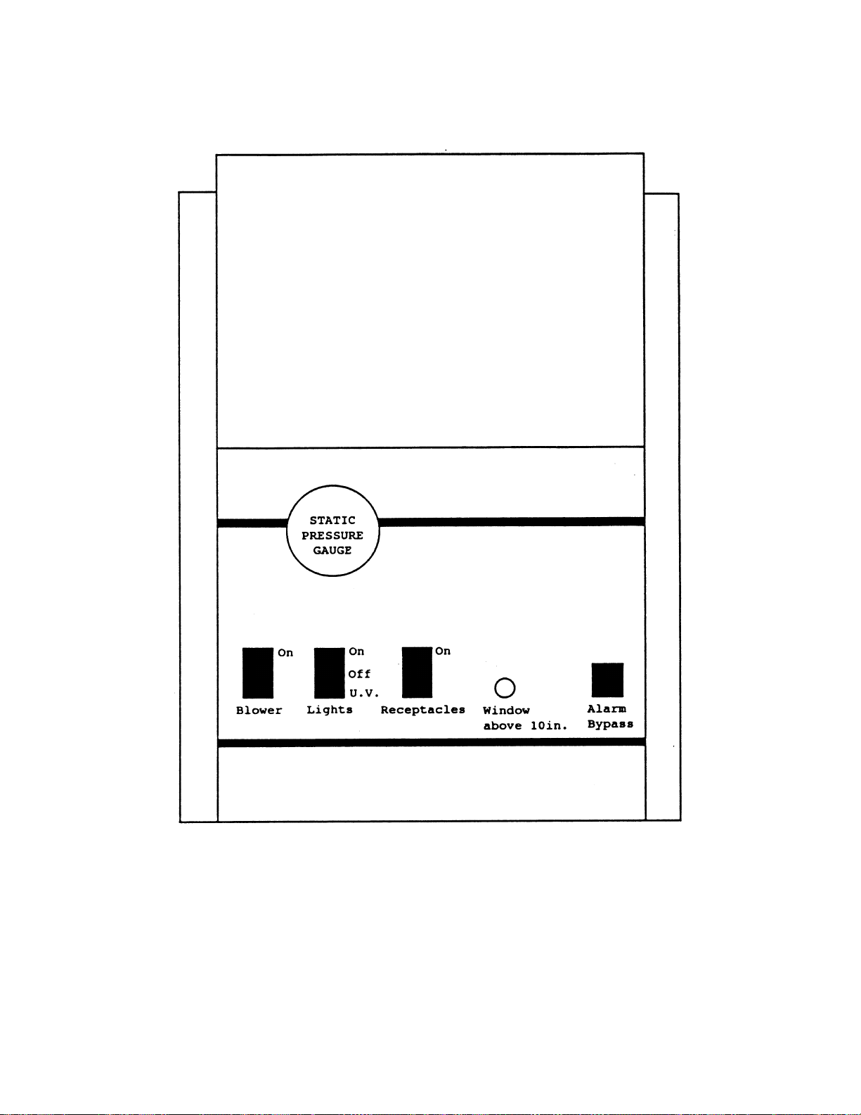
SECTION 4.3
DRAWING #4.1
OVERVIEW OF 1184/1186
CONTROL PANEL
19
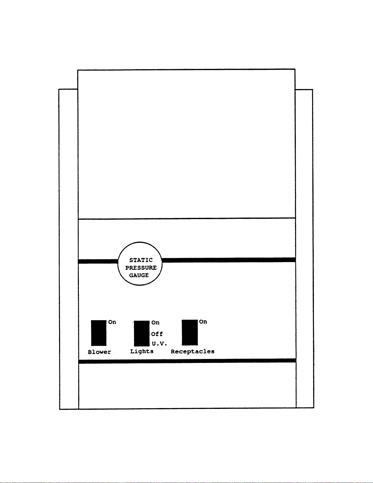
SECTION 4.4
DRAWING #4.2
OVERVIEW OF 1194/1196 CONTROL PANEL
20
Other manuals for 1184
2
This manual suits for next models
4
Table of contents
Other Forma Scientific Laboratory Equipment manuals

Forma Scientific
Forma Scientific 3911 User manual

Forma Scientific
Forma Scientific 1184 User manual

Forma Scientific
Forma Scientific 1122 User manual

Forma Scientific
Forma Scientific 1284 User manual

Forma Scientific
Forma Scientific 3911 User manual

Forma Scientific
Forma Scientific 3940 Operating instructions

Forma Scientific
Forma Scientific 1284 User manual

Forma Scientific
Forma Scientific 3911 User manual

Forma Scientific
Forma Scientific 1184 User manual

Forma Scientific
Forma Scientific 3920 User manual


