TMS Lite ANGX-1000-CH1-24V User manual
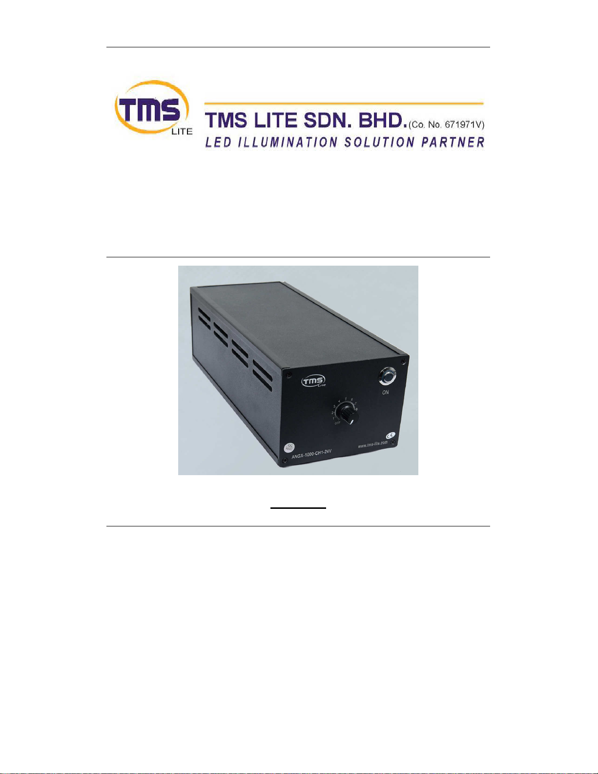
TMS Lite ANALOG LIGHTING CONTROLLER UNIT
MODEL
ANGX-1000-CH1-24V
USER MANUAL
Rev 1.2 21
th
April 2014

TMS Lite ANALOG LIGHTING CONTROLLER UNIT
- i-
Contents
Introduction........................................................................................................................................1
Features List...................................................................................................................................1
Applications ...................................................................................................................................1
Hardware............................................................................................................................................2
Packing List....................................................................................................................................2
Front Panel.....................................................................................................................................2
Rear Panel......................................................................................................................................3
Power ON.......................................................................................................................................3
Constant.........................................................................................................................................3
ANGX-1000-CH1 SPECIFICATIONS ...............................................................................................4
Configuration .............................................................................................................................4
Precautions.................................................................................................................................4
CONTROLLER DRAWING LAYOUT..............................................................................................5
CABLE SELECTION ........................................................................................................................6
LIGHTING CONNECTORS ..............................................................................................................7
POWER CORD..................................................................................................................................7

TMS Lite ANALOG LIGHTING CONTROLLER UNIT
- 2-
Revision Notes
Rev
Date/Author
Comment
1.0 KW NG First Release
1.2 KW NG Second Release

TMS Lite ANALOG LIGHTING CONTROLLER UNIT
- 1-
Introduction
Features List
•1-Channel Analog Control LED light source.
•Variable constant current intensity control for LED lighting
•AC Power Input is 100V - 240V AC 50/60 Hz.
•Lighting Output Voltage 24V DC maximum.
•Maximum output current is selectable, 3A or 5A (select by toggle switch at rear panel).
Applications
•Manual variable Light Control for LED lighting.
•General purpose LED light intensity control.
TMS Lite ANALOG LIGHTING CONTROLLER UNIT
- 2-
Hardware
Packing List
Please make sure that the following parts are in the packing list:
1.
1.1.
1. ANGX-1000-CH1-24V lighting controller unit
AC Power Cord 110V AC or 240V AC
LED Lightings (Optional)
Ext. Lighting Cable (Optional)
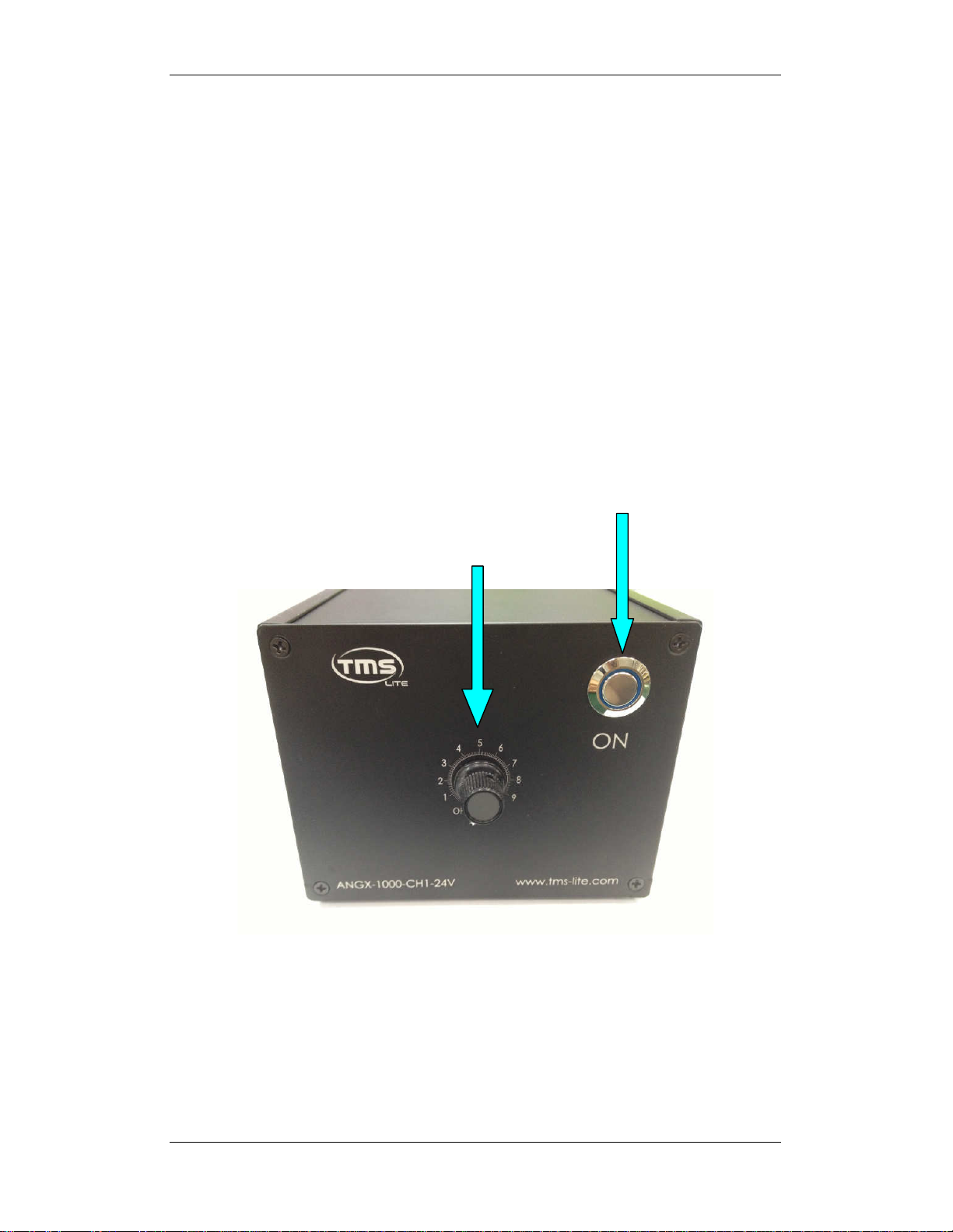
Front Panel
The front panel consists of VR KNOB (Control LED Intensity range from 0~10) and
a Push Button Switch (ON/OFF Power)
Push Button
(ON/OFF Switch)
VR Intensity Control

TMS Lite ANALOG LIGHTING CONTROLLER UNIT
- 3-
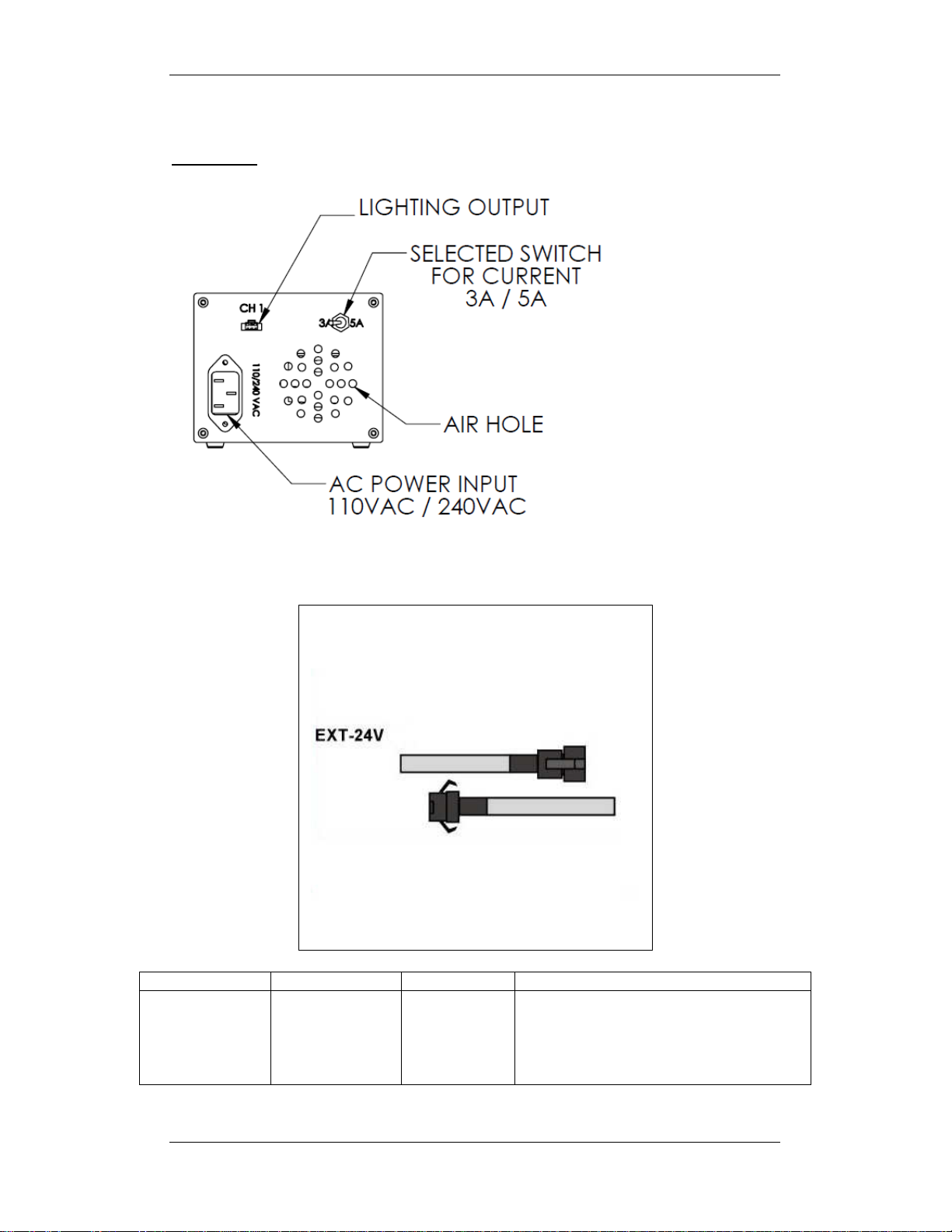
Rear Panel
The rear panel consists of 3-Pin AC Plug, Lighting Output Connector and
Current Select Switch ( Set the maximum output current to either 3A or 5A )
Power ON
The maximum output current setting for the controller is either 3A or 5A. The current setting is
selectable by a toggle switch on the rear panel of the unit. Position the Current Select Switch
at 3A (left) will set the maximum output current to 3 Amps. Position the Current Select Switch
at 5A (right) will set the maximum output current to 5 Amps.
Please make sure only 24V LED Lighting is connected to Lighting Output connector before
power on the unit.
Connect a power cord cable to 100V - 240V AC supply line to the controller chassis plug for
supply AC voltage to controller.
The BLUE LED inside the Button will light up when user has switch ON the unit by pressing
the Push Button once. Pressing the Push Button once again will switch OFF the unit.
Operating Modes
•Constant (Analog VR intensity control)
Constant
The unit produces constant output current which is controlled by VR Knob from 0 to 10
(Analog).
VR Knob controls the lightings intensity.
The Lightings intensity is set by manually adjust the position of VR Knob (label 0-10) at the
front panel of the unit.
When VR Knob position at 'OFF', it sets the lightings intensity at ‘0’.
When VR Knob position at '1', it sets the lightings intensity at minimum.
When VR Knob position at '10', it sets the lightings intensity at maximum.
Lighting Output
Power Input
(Chassis Plug)
( 100V -
240V AC
50/60 Hz)
Current Select Switch
Left Position: 3A
Right Position: 5A
TMS Lite ANALOG LIGHTING CONTROLLER UNIT
- 4-
ANGX-1000-CH1 SPECIFICATIONS
CONTROL:
VR Knob
Manual Control (Adjustable)
General:
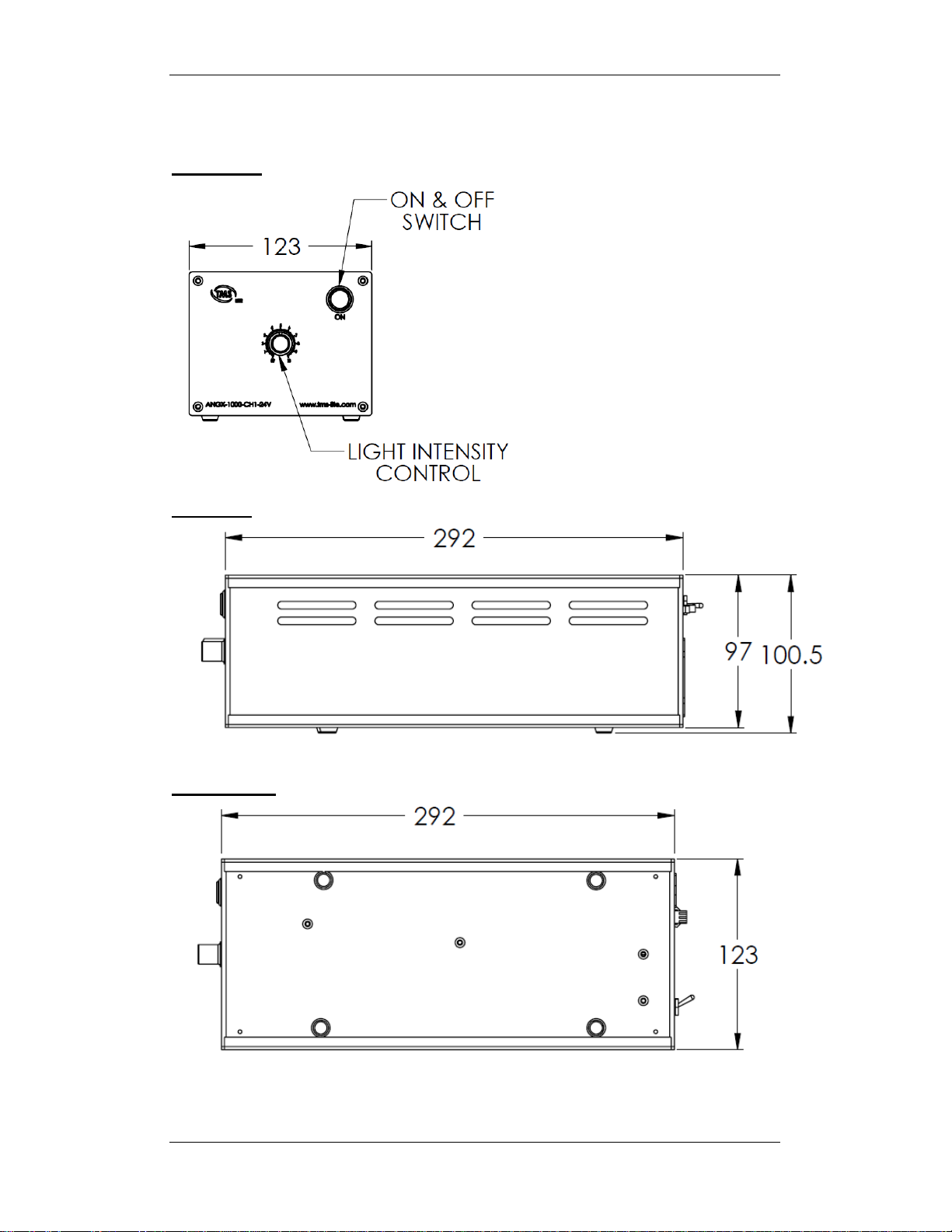
Dimension L:330 mm W:123 mm H:93mm
Power Input 100V - 240V AC 50/60 Hz (240W)
Board Max Power Consumption 5.5A @ 26.5V
Board Voltage 26.5VDC
Channels:
1 Channel
Output Mode Constant
Output Current Selectable maximum current 3A or 5A
From 130mA up to 5A
Lighting Output
Voltage
24V Max.
Functions:
Constant Lighting Intensity VR Adjustable
Intensity Range 0 ~ 10 steps
Note: The intensity of light is affected by the length of the lighting cable.
Configuration
Connections:
For ANGX-1000-CH1-24V to operate properly, the unit terminals must be connected
correctly. The terminals voltage polarity must be followed accordingly to prevent
damage to the unit.
−
Supply Voltage Selection
The unit can operate on 100V AC - 240V AC.
−
Power Input Terminals
Connect the Power Cord Cable to 3-pin chassis plug of controller.
Connect a power cord cable to 100V - 240V AC supply line to the controller
chassis plug for supply AC voltage to controller.
−
Lightings Output Terminals Channel (CH1)
The lighting connector is to be connected to 24V-Lighting
Precautions
−Do not open the cover of the product
Electric shock may occur, do not touch the internal parts.
−Install the unit at a site with good ventilation
Poor ventilation result over heating and cause the unit to fail.
−Do not use the unit in a closed system, as it becomes hot
Cool down with fans, if it is used in a close space.
−Do not rest your hand or any part of your body on the product casing
Warning: The casing of the product is hot. Its temperature may raise to 80 °C.
TMS Lite ANALOG LIGHTING CONTROLLER UNIT
- 5-
CONTROLLER DRAWING LAYOUT
Front View:
Side View:
Bottom View:
TMS Lite ANALOG LIGHTING CONTROLLER UNIT
- 6-
Rear View:
CABLE SELECTION
MODEL
POWER
LENGTH
APPLICATIONS
EXT-24V 24V
1M
2M
3M
4M
5M
•Used to connect a 24V lighting to
ANG & ANGX SERIES

TMS Lite ANALOG LIGHTING CONTROLLER UNIT
- 7-
LIGHTING CONNECTORS
24V-Lighting Connector
Pin 1 -- Brown wire (+ve) Pin 3 -- White wire (-ve)
POWER CORD
240VAC Power Cord
110VAC Power Cord
Table of contents
Other TMS Lite Controllers manuals


Popular Controllers manuals by other brands


FXLuminaire
FXLuminaire Luxor ZD quick start guide

Supmeter
Supmeter BST100-B11 Operation manual

ITOH DENKI
ITOH DENKI Power Moller CBM-105FP1-EU1 Technical documentation

Lynxspring
Lynxspring BW437-FCU-LX quick guide

Regin
Regin Regio Mini Series instructions

Phoenix Contact
Phoenix Contact ILC 330 user manual