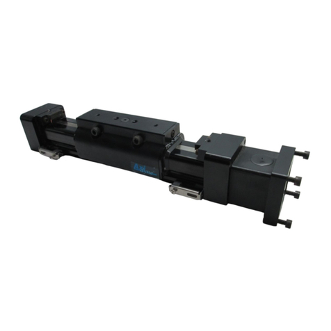
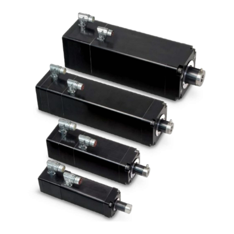
Tolomatic TRS Series User manual

3600-4225_00 TRS Manual 1 Last Revision: 3/1/2022
MANUAL
For Installation, Maintenance
and Operation
TRS Series Actuators
LINEAR SOLUTIONS MADE EASY

3600-4225_00 TRS Manual 2 Last Revision: 3/1/2022
Original instructions in English. Translations in community languages supplied as required.
Information furnished is believed to be accurate and reliable. However, Tolomatic assumes no responsibility for its
use or for any errors that may appear in this document.
Tolomatic reserves the right to change the design or operation of the equipment described herein and any
associated motion products without notice. Information in this document is subject to change without notice.
Copyright ©2022 Tolomatic, Inc. All Rights Reserved
All brand and product names are trademarks of their respective owners. Information in this document is
believed to be accurate at time of publication.

3600-4225_00 TRS Manual 3 Last Revision: 3/1/2022
CONTENTS
•CONTENTS .............................................................................................................................................3
•List of Figures & Tables............................................................................................................................5
1: Safety.........................................................................................................................................................................6
•1.1 Safety Symbols ..................................................................................................................................6
•1.2 Safety Considerations ........................................................................................................................6
2: TRS Product Overview...............................................................................................................................................8
•2.1 General Description............................................................................................................................8
•2.2 Product Features................................................................................................................................8
•2.3 Installation..........................................................................................................................................9
•2.4 Identification Label .............................................................................................................................9
•2.5 Manufacturer ......................................................................................................................................9
3: TRS Actuator Product Configuration........................................................................................................................10
•3.1 Tolomatic TRS Actuator Series Configuration..................................................................................10
•3.2 Standard Configurations and Options ..............................................................................................10
•3.2.1 Motor (Gearhead) Mounting..........................................................................................................12
•3.2.2 Actuator Mounting .........................................................................................................................12
•3.2.3 Carrier Style Choices ....................................................................................................................12
4: TRS Mechanical Installation.....................................................................................................................................13
•4.1 General Operation............................................................................................................................13
•4.2 Loads and critical speed...................................................................................................................13
•4.3 Mechanical Installation.....................................................................................................................13
•4.4 Motor Installation..............................................................................................................................14
•4.4.1 Reverse Parallel (RP) Configuration ............................................................................................14
•4.4.2 Inline (LMI) Configuration..............................................................................................................17
•4.5 Actuator Mounting ............................................................................................................................17
•4.5.1 Standard Bottom Mounting............................................................................................................17
•4.5.2 Toe Clamp Mounting.....................................................................................................................18
•4.5.3 “Carrier-To-Carrier” Mounting........................................................................................................18
•4.5.4 Switch Mounting............................................................................................................................19
5: TRS Operation and Start up Considerations............................................................................................................20
•5.1 Back Driving.....................................................................................................................................20
•5.2 Homing.............................................................................................................................................20

3600-4225_00 TRS Manual 4 Last Revision: 3/1/2022
•5.3 Breather/Purge Port Operation.........................................................................................................20
6: TRS Repair and Maintenance..................................................................................................................................21
•6.1 Dust Bands Replacement.................................................................................................................21
•6.2 Lubrication (for TRS actuator equipped with optional access covers)..............................................22
•6.3 Storage Recommendations..............................................................................................................23
Appendix A: Performance & Mechanical Specifications...............................................................................................24
Appendix B: Troubleshooting.......................................................................................................................................24
Appendix C: Warranty..................................................................................................................................................25
•C.1 Warranty..........................................................................................................................................25
Appendix D: Declaration of Incorporation.....................................................................................................................27

3600-4225_00 TRS Manual 5 Last Revision: 3/1/2022
List of Figures & Tables
Figure 2.1: Tolomatic TRS Actuator...............................................................................................................................8
Figure 2.2: TRS major components ...............................................................................................................................8
Figure 2.3: Tolomatic TRS Actuator identification label. ................................................................................................9
Figure 3.1: Tolomatic TRS actuator ordering codes and descriptions .........................................................................11
Figure 3.2: TRS actuator reverse parallel and inline motor choices.............................................................................12
Figure 3.3: TRS actuator mounting..............................................................................................................................12
Figure 3.4: TRS carrier styles ......................................................................................................................................12
Table 4.1: Reverse Parallel (RP) motor fastener torque requirements ........................................................................14
Figure 4.1: Reverse parallel (RP) belt clearance required ...........................................................................................14
Table 4.2: Motor fastener torque requirements............................................................................................................15
Figure 4.2: Reverse parallel (RP) tensioning screw.....................................................................................................15
Table 4.3: Sonic tension meter parameters .................................................................................................................16
Figure 4.3: Belt pulley diagram ....................................................................................................................................16
Figure 4.4: Placement of coupler half on motor shaft...................................................................................................17
Table 4.4: Inline (LMI) motor fastener torque requirements .........................................................................................17
Table 4.5: TRS bottom mounting torque requirements ................................................................................................18
Figure 4.5: TRS toe clamp ...........................................................................................................................................18
Figure 4.6: TRS carrier to carrier mounting examples .................................................................................................18
Table 4.6: TRS Carrier to Carrier torque requirements................................................................................................19
Figure 4.7: Switch in rail of TRS actuator.....................................................................................................................19
Figure 5.1: Breather/Purge port on TRS actuator ........................................................................................................20
Figure 6.1: Dust band replacement illustration.............................................................................................................21
Figure 6.2: Optional access covers are located centered on each side of the actuator...............................................22
Figure 6.3: Position the carrier to permit lubrication of each of the 4 linear bearings...................................................22
Table 6.1: Lubrication quantity recommendations for TRS actuators ..........................................................................23

3600-4225_00 TRS Manual 6 Last Revision: 3/1/2022
1: SAFETY
1.1 Safety Symbols
General
Read completely through the applicable sections of the manual before the equipment/unit is unpacked, installed or
operated. Pay careful attention to all of the dangers, warnings, cautions and notes stated in the manual.
Serious injury to persons or damage to the equipment may result if the information in the manual is not followed.
Safety Symbols
Items that are specifically marked DANGER, WARNING, CAUTION, PROHIBITIVE, MANDATORY ACTION, or
NOTE! are arranged in a hierarchical system and have the following meaning:
Indicates a very hazardous situation which, if not avoided, could result in death or serious injury. This signal word is
limited to the most extreme situations.
Indicates a potentially hazardous situation which, if not avoided, could result in death or serious injury.
Indicates a potentially hazardous situation which, if not avoided, may result in property damage, minor or moderate
injury.
Indicates Prohibited Action
Indicates Mandatory Action
Information that requires special attention is stated here.
1.2 Safety Considerations
Proper and Safe Use of Product
Fail-Safe e-Stop Recommendations
After motor has been installed a means for a fail-safe e-stop is highly recommended to ensure equipment and
personal safety. The e-stop should be able to remove power from the actuator to stop and/or prevent any undesired
motion.
Device Damage Prevention
To prevent permanent damage to the device published speed and load ratings should never be exceeded. In
addition, proper mechanical assembly should be verified and safety measures checked before applying power to the
complete equipment package.

3600-4225_00 TRS Manual 7 Last Revision: 3/1/2022
Personal Safety
During normal operation the motor can become hot. In addition, the case ground of the appropriately marked electric
motor should be tied to an earth ground to prevent the presence of case voltage.
During normal operation, the actuator carrier travels back and force creating a possible point of collision or contact
with personnel resulting in physical damage. Proper guarding and signage must be used to prevent the above.
Handling and Unpacking
When unpacking and handling the actuator, care should be taken not to drop the actuator as this can damage the
internal mechanical components, electrical connectors or cause misalignment of feedback device, leading to poor
performance or loss of functionality. Since this is an electro-mechanical device, proper ESD (Electro Static
Discharge) measures should be taken to avoid static electricity from contacting the signal and power lines of the
device.
Packing and Transport
Package actuator to prevent damage during transport. It is recommended that the actuator be returned in its original
packaging. If the original packaging is not available, then follow these recommendations.
1. Make sure the actuator is clean, dry and protected from moisture.
2. Foam in place if possible.
3. Reinforce ends of box with multiple layers of cardboard or wood to prevent the actuator from
breaking through the packaging during shipment.
4. It is best to ship one unit per container because individual items that are not isolated with stable
packaging (foam in place) from each other often get damaged during shipment.
5. When shipping more than one unit in a single container, it is recommended to foam in place to
prevent damage during shipping to both the units and the packaging.
Modifications to the Equipment
Requirements Regarding Personnel
All personnel must be completely informed regarding all safety regulations and the function of the equipment.
When installed, pinch points are generated capable of damaging forces. The risk
area surrounding the TRS must either be guarded or clearly marked, including
display signage in accordance with all applicable national and international legal
requirements. The risk area must be protected by a safety system that stops the
equipment if anyone enters the risk area. Personnel who enter the risk area must be
authorized, trained and qualified for the different tasks inside the risk area.

3600-4225_00 TRS Manual 8 Last Revision: 3/1/2022
2: TRS PRODUCT OVERVIEW
2.1 General Description
Tolomatic TRS Actuators
Figure 2.1: Tolomatic TRS Actuator
TRS series is a family of ball or roller screw driven mechanical rodless band style linear actuators manufactured by
Tolomatic Inc. to customer specified stroke length and mounting provisions for customer specified motor (gearhead)
and are intended for use in general purpose industrial applications.
The product family includes the following models: TRS100 and TRS165.
An appropriately marked electric motor or a motor (gearhead) assembly is coupled with the input shaft of the
actuator to create linear motion. The motor (gearhead) may be installed by the customer at their facility or by
Tolomatic.
2.2 Product Features
Figure 2.2: TRS major components

3600-4225_00 TRS Manual 9 Last Revision: 3/1/2022
2.3 Installation
The TRS is a compact screw drive rodless band style linear actuator. The TRS provides linear motion of the carrier
developing the required thrust force and velocity in a variety of applications.
Before installation and commissioning of the equipment, this manual and all accompanying manufacturer documents
and manuals MUST be completely read by the appropriate personnel. All warning texts must be given special
attention.
2.4 Identification Label
Figure 2.3: Tolomatic TRS Actuator identification label.
Do not remove the identification label. Do not render it unreadable.
2.5 Manufacturer
Tolomatic, Inc.
3800 County Road 116, Hamel, MN 55340, USA
Phone: 763-478-8000
Sales@Tolomatic.com

3600-4225_00 TRS Manual 10 Last Revision: 3/1/2022
3: TRS ACTUATOR PRODUCT CONFIGURATION
3.1 Tolomatic TRS Actuator Series Configuration
TRS Series Standard Configurations and Options
•TRS series includes two actuator models: TRS100 and TRS165
•Each of the TRS actuator models is available with a choice of a ball screw with 5 mm or 10 mm
lead; in addition TRS165 actuators are also available with roller screws with 5 mm and 10 mm
lead;
•Each of the TRS actuator models is available with Inline or Reverse Parallel motor (gearhead)
mounting configurations;
•Orientation of the motor (gearhead) with respect to the actuator in a Reverse Parallel motor
mounting configuration (“top”, “bottom”, “left” or “right”) is specified by the customer;
•Each of the TRS actuator models is available with either a standard (threaded holes on the bottom
of the actuator base) or optional toe clamp mounting
•Each of the TRS actuator models is available with a choice of externally mounted positioning
sensors (switches)
For performance data and specifications please refer to the Tolomatic TRS Product Catalog 3600-4222.
3.2 Standard Configurations and Options
Please see Tolomatic TRS Product Catalog 3600-4222 for complete information on ordering codes. Please use 3D
CAD files available at www.tolomatic.com for critical dimensions.

3600-4225_00 TRS Manual 11 Last Revision: 3/1/2022
Figure 3.1: Tolomatic TRS actuator ordering codes and descriptions

3600-4225_00 TRS Manual 12 Last Revision: 3/1/2022
3.2.1 Motor (Gearhead) Mounting
Figure 3.2: TRS actuator reverse parallel and inline motor choices
Each of the TRS actuators is available in Reverse Parallel or Inline motor (gearhead) mounting
configuration; Timing belt reduction drive in the Reverse Parallel configuration is available with 1:1
reduction ratio; Motor (gearhead) can be installed by the Customer at their facility or at Tolomatic.
3.2.2 Actuator Mounting
Standard base bottom mount
Optional toe clamp mount
Figure 3.3: TRS actuator mounting
All of the TRS actuators are available with the following mounting options:
Standard base bottom mount; Toe clamp mount.
3.2.3 Carrier Style Choices
Figure 3.4: TRS carrier styles
TRS100 is available with either a standard or an optional CTC (“carrier to carrier”) carrier design. CTC
carrier allows a TRS100 actuator to be mounted “carrier to carrier” onto another TRS100 or a TRS165
actuator to create a 2-axis system with no need for transition plates.

3600-4225_00 TRS Manual 13 Last Revision: 3/1/2022
4: TRS MECHANICAL INSTALLATION
Prior to installation and commissioning of this equipment this Manual and all accompanying manufacturer
documents and manuals MUST be completely read by the appropriate personnel. All warnings must be
given special attention.
4.1 General Operation
TRS series linear actuators function by translating rotary motion of an externally mounted electric motor
into a linear motion of the load mounted on the carrier using a ball screw or a planetary roller screw
mechanism. The carrier rides on linear bearings attached to the base of the actuator. The travel
coordinates, linear speed, acceleration and force are typically controlled by a servo drive.
The relationship between the rotary motion of the motor and the linear motion of the actuator corresponds
to the following relationships:
Linear distance traveled (mm) = number of screw revolutions x screw lead (mm)
Linear speed (mm/sec) = screw RPM/60 x screw lead (mm)
Linear force (N) = [motor torque (Nm)/1000 x 2 x πx reduction ratio x screw efficiency]/screw lead (mm)
Care should be taken not to exceed the physical travel limits of the actuator. Exceeding the specified stroke will
cause the actuator to reach mechanical end of stroke internally. Although protected by the end of stroke bumpers,
reaching internal end of stroke at speeds and torque greater than those used to home (less than 25mm/sec and low
torque) may physically damage the screw and the internal components of the actuator.
4.2 Loads and critical speed
Exceeding the specified load limits of the bearing system will lead to reduction of its service life. Exceeding
critical speed of the linear motion will lead to increased vibration and heat generation that may cause
premature wear and reduced service life of the actuator.
4.3 Mechanical Installation
1. Open the crate and remove packaging material
2. Carefully remove linear actuator from the crate
3. Visually inspect the actuator for damage
4. Notify the carrier of any shipping damage immediately
5. Move the actuator to its position
6. If the actuator is mounted in a vertical or inclined position include safety measures to prevent load
from falling in the case of screw failure or loss of power
7. Ensure sufficient clearance around the actuator to allow for airflow and cooling
8. Follow installation mounting instructions for each configuration.

3600-4225_00 TRS Manual 14 Last Revision: 3/1/2022
4.4 Motor Installation
4.4.1 Reverse Parallel (RP) Configuration
When the motor (gearhead) is installed by the Customer at their facility, TRS actuator is shipped with
socket head cap screws holding the RP Cover and the RP Plate “hand tight” and the motor (gearhead)
fasteners, the timing belt and pulley and the Keyless Locking Device (KLD) separate.
To install the motor (gearhead):
a. Remove the RP cover;
b. Assemble the motor (gearhead) on the actuator RP plate by tightening the motor fasteners to the
values below.
FASTENER SIZE
TORQUE
(Nm)
(lbf-in)
M3
1.0
9
M4
3.0
27
M5 5.0 44
M6
8.0
71
Table 4.1: Reverse Parallel (RP) motor fastener torque requirements
c. Assemble the timing pulley on the motor (gearhead) shaft using the supplied KLD according to the
following procedure:
•Check to ensure that locking screws, taper, shaft and bore contact areas are clean and
thoroughly lubricated with a coating of light machine oil;
•The connector does not require a key for its operation; if the motor (gearhead) is supplied with
a key, it needs to be removed. The radial slit of the locking connector’s inner ring should be
positioned approximately opposite the keyway, and one of the locking screws should be
positioned directly over the keyway;
•Insert the KLD into the pulley bore and place the pulley onto the motor (gearhead) shaft. The
pulley must be located on the shaft such that the distance between the back of the pulley and
the face of the RP plate is equal to 1.60 mm (.063”);
Figure 4.1: Reverse parallel (RP) belt clearance required

3600-4225_00 TRS Manual 15 Last Revision: 3/1/2022
•Tighten all the locking screws until the screw heads are in contact with the face of the front
flange;
•Use a torque wrench set approximately 5% higher that the specified tightening torque value
from the table below:
TORQUE
MOTOR SHAFT DIAMETER
NUMBER OF
FASTENERS
FASTENER
SIZE (Nm) (lbf-in)
1/4"
3
M4
4.5
40
5/16", 3/8"; 6mm, 8mm, 10 mm 3 M4 5.0 44
1/2"; 11 mm; 12 mm
4
M4
5.0
44
5/8"; 14 mm; 15 mm; 16 mm 6 M4 5.0 44
Table 4.2: Motor fastener torque requirements
•Starting with a locking screw adjacent to the slit and moving in the direction away from the slit
tighten the screws in a circular pattern using quarter turns for each screw several times until
quarter turns can no longer be achieved. At this point apply the 5% overtorque for two more
complete times around;
•Reset the torque wrench to the specified torque value and ensure that none of the screws can
be turned;
•If at any point the KLD needs to be removed, take out the locking screws and use jacking
holes located on the face of the front flange. The KLD is released by evenly and gradually
tightening the screws inserted into the jacking holes, using quarter turns for each screw;
d. Remove four M6 fasteners attaching the RP plate to the actuator one by one, apply medium
strength thread adhesive (Loctite 242 or 248 or equivalent) and hand tighten them making sure
they will allow the RP plate to move along the surface of the head;
e. Place the timing belt around both pulleys taking care to avoid contact with sharp corners or edges
f. Make sure that the fasteners attaching the RP plate to the actuator head are not tightened;
g. Tension the timing belt by rotating the tensioning screw located at the bottom of the Reverse
Parallel Plate while verifying the tension value by using either a sonic tension meter or a force
deflection method. For proper operation timing belt should be tensioned to 90-110 N (20-25 lbf);
Figure 4.2: Reverse parallel (RP) tensioning screw

3600-4225_00 TRS Manual 16 Last Revision: 3/1/2022
•Sonic tension meter
i. Enter the following sonic tension meter parameters:
PARAMETER
UNITS
VALUE
TIMING BELT MASS
g/m
3.9
TIMING BELT WIDTH
mm
15
SPAN LENGTH
mm
125
Table 4.3: Sonic tension meter parameters
ii. Measure the span tension using the sonic meter manufacturer’s recommendations
•Force deflection method
i. Ensure one of the pulleys is free to rotate
ii. The force required to deflect the belt at the center of the span by 3 mm (.12”) should be
18-27 N (4-6 lbf)
Figure 4.3: Belt pulley diagram
h. Tighten the M6 fasteners attaching the RP plate to the actuator head to the torque value of 8.0 Nm
(72 lbf-in);
i. Reassemble the RP cover and tighten its M5 fasteners to 5.0 Nm (44 lbf-in).

3600-4225_00 TRS Manual 17 Last Revision: 3/1/2022
4.4.2 Inline (LMI) Configuration
When the motor (gearhead) is installed by the Customer at their facility, TRS actuator is shipped with the
motor (gearhead) fasteners and the coupling half separate.
To install the motor (gearhead):
a. Assemble the coupling half on the motor (gearhead) shaft such that the end of the motor shaft is
approximately 0.76 mm (.030”) off the face of the coupling half (see the picture below). Secure the
coupling half with M4 fasteners tightened to 3.0 Nm (27 lbf-in). Medium strength thread adhesive
is recommended.
Figure 4.4: Placement of coupler half on motor shaft
b. Carefully align the coupling half with the mating half on the actuator’s drive shaft and move the
motor (gearhead) in until it is fully seated on the LMI motor spacer. Tighten the motor fasteners to
the values below (medium strength thread adhesive recommended).
FASTENER
SIZE
TORQUE
(Nm)
(lbf-in)
M3
1.0
9
M4
3.0
27
M5
5.0
44
M6
8.0
71
Table 4.4: Inline (LMI) motor fastener torque requirements
4.5 Actuator Mounting
4.5.1 Standard Bottom Mounting
TRS100 and TRS165 actuators may be located/aligned with M6 dowel pins and secured to a surface with
M8 fasteners. M8x1.25 threaded mounting holes are located on the bottom of the actuator base, the
number of holes varies with the length of the actuator. Dowel pins and fasteners are not included. Please
see Tolomatic TRS Product Catalog 3600-4222 for the dimensional drawings.

3600-4225_00 TRS Manual 18 Last Revision: 3/1/2022
METRIC FASTENERS
MODEL NUMBER OF
DOWEL PINS
DOWEL
PIN SIZE
NUMBER OF
FASTENERS
PROPERTY
CLASS
FASTENER
SIZE
TORQUE
lb-in
(Nm)
TRS100 2 6 AS REQUIRED 12.9 M8 354 40
TRS165 2 6 AS REQUIRED 12.9 M8 354 40
Table 4.5: TRS bottom mounting torque requirements
4.5.2 Toe Clamp Mounting
TRS100 and TRS165 actuators may be supplied in a toe clamp mounting option (see picture). Toe clamps
are used in pairs. After their tabs have been placed into grooves on the sides of the actuator base the toe
clamps are secured to the surface with M10 fasteners (socket head cap or button head screws). Proper
tension torque should be applied to the fasteners.
Figure 4.5: TRS toe clamp
4.5.3 “Carrier-To-Carrier” Mounting
Available “Carrier-To-Carrier” mounting used for constructing 2-axis motion actuator systems allows to
mount a carrier of a TRS100 actuator directly to a carrier of another TRS100 or a TRS165 actuator and
perpendicular to that actuator without help of transition plates (see the picture below).
TRS100 to TRS100
TRS100 to TRS165
Figure 4.6: TRS carrier to carrier mounting examples

3600-4225_00 TRS Manual 19 Last Revision: 3/1/2022
METRIC FASTENERS
MODEL NUMBER OF
DOWEL PINS
DOWEL
PIN SIZE
NUMBER OF
FASTENERS
PROPERTY
CLASS
FASTENER
SIZE
TORQUE
lb-in
(Nm)
TRS100 TO TRS100 2 6 AS REQUIRED 12.9 M6x1.0 142 16.0
TRS165 TO TRS165 2 8 AS REQUIRED 12.9 M6x1.0 142 16.0
Table 4.6: TRS Carrier to Carrier torque requirements
4.5.4 Switch Mounting
Place switches in the groove in the switch rail at desired location with Tolomatic facing outward (see the
picture below). While applying light pressure to the switch rotate the switch into the groove and lock it
securely into place by tightening the screw on the switch.
Figure 4.7: Switch in rail of TRS actuator

3600-4225_00 TRS Manual 20 Last Revision: 3/1/2022
5: TRS OPERATION AND START UP CONSIDERATIONS
5.1 Back Driving
TRS actuators are equipped with ball and roller screws that are not self-braking and will not hold position
under load. When there is no current/torque input to the drive motor, the screw will rotate and the carrier
can move freely. A motor brake option should be used if the motion system/axis requires the actuator to
hold position when it is not powered, or as a safety measure if the actuator is mounted in a vertical
orientation to prevent the payload from free falling in the event of unintended power loss.
5.2 Homing
To establish full open and close position of the actuator, set the drive torque limits to the lowest values possible for
motion (10-20% to begin with) and use a slow velocity jog command (<1mm/s) to search for the hard limits. If 10-
20% of the continuous current is not sufficient to drive both the actuator installed on the equipment, slowly increase
the current limit until the unit is able to move to both the fully open and fully closed positions. Proper care must be
taken when finding limits after installation of the equipment. Applying a load in excess of the continuous rated force
at the end of travel may cause internal damage and could render the assembly inoperable or cause damage.
Once the full open and closed positions are determined, these values can be stored in the drive/controller as travel
limits.
5.3 Breather/Purge Port Operation
The 1/8-27 NPTF port on the face of the actuator head can be used as a “purge port” for providing positive
pressure to the interior of the actuator with the purpose of preventing ingress of contaminants. It is
recommended that the supplied air is dry and clean, and the air line should be periodically inspected for
moisture.
Figure 5.1: Breather/Purge port on TRS actuator
This manual suits for next models
2
Table of contents
Other Tolomatic Controllers manuals

Tolomatic
Tolomatic Axidyne AXIOM PLUS PV Series User manual

Tolomatic
Tolomatic IMA-S Series User manual

Tolomatic
Tolomatic BCS10 Operator's manual

Tolomatic
Tolomatic 3604-9651 Manual

Tolomatic
Tolomatic SmartActuator Series User manual

Tolomatic
Tolomatic ACS Manual

Tolomatic
Tolomatic ServoWeld CSW Owner's manual

Tolomatic
Tolomatic IMA Series User manual

Tolomatic
Tolomatic ACS Manual

Tolomatic
Tolomatic RSX User manual