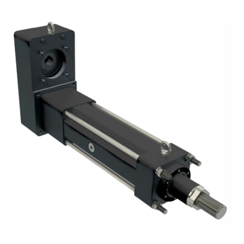
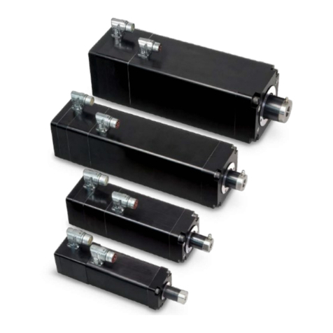
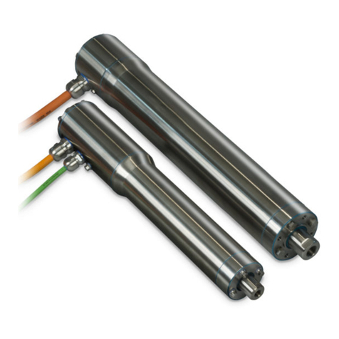
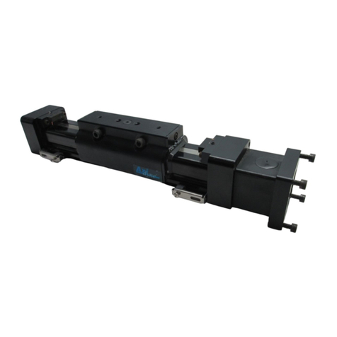
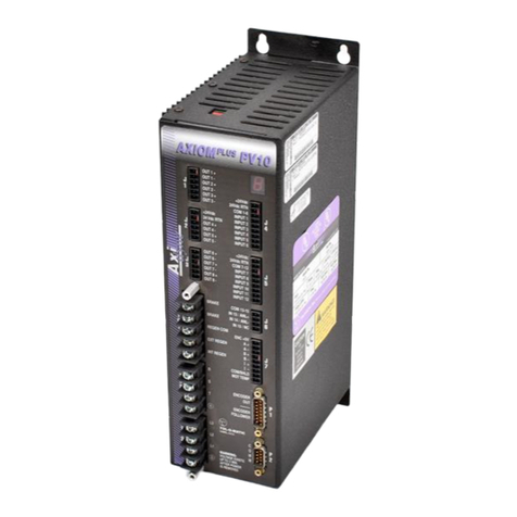
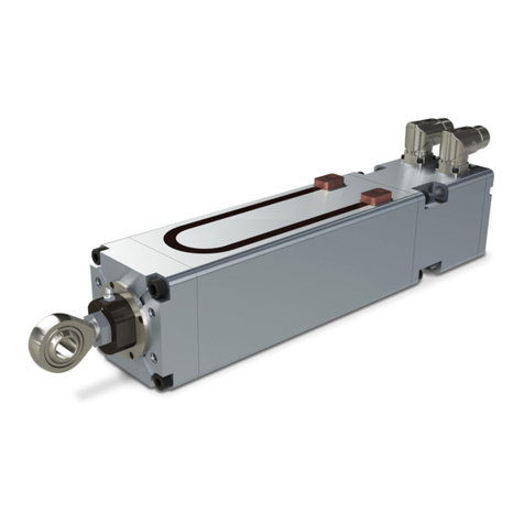
Tolomatic SmartActuator Series User manual

USER GUIDE
LINEAR SOLUTIONS MADE EASY
SmartActuator Series
Integrated Control
Rod Style Actuator & Motor
ICRSV1B BASIC
ICRSV1P PLUS
ICMSV1P PLUS
2100-4001_04_ICR_USERGUIDE

Tolomatic reserves the right to change the design or operation
of the equipment described herein and any associated motion
products without notice. Information in this document is
subject to change without notice.
201503261442
Original Instructions - English
Translations will be supplied in other community languages
as required by customers

Tolomatic User Guide: ICR Rod Style Integrated Control Actuator i
Contents
List of Figures..................................................................................................iv
Health and Safety Regulations........................................................................vi
EMC Guidelines........................................................................................... vii
Proper and Safe Use of Product ................................................................... vii
1 ICR Basic and ICR/ICM Plus Product Overview ...................................1-1
1.1 The SV1B Basic and SV1P Plus SmartActuators ...................................1-1
1.1.1 SV1B Basic Overview..................................................................1-1
1.1.2 SV1P Plus Overview....................................................................1-2
1.1.3 ICR Options................................................................................1-3
1.1.4 ICR Mechanical Specifications.....................................................1-5
1.1.5 ICR Speed and Thrust Curves......................................................1-6
1.1.6 RMS Thrust and Velocity Considerations ......................................1-7
1.1.7 ICR Screw Life............................................................................1-7
1.1.8 ICR System Critical Speed...........................................................1-8
1.1.9 Side Load Considerations............................................................1-8
1.1.10 Brake Considerations................................................................1-8
1.1.11 ICM Plus Mechanical Specs ......................................................1-8
1.1.12 ICM Plus Motor Speed vs Torque ...............................................1-8
2 ICR SV1B Basic - Electrical Interface, Specs & Wiring........................2-1
2.1 Cabling and Connectors – ICR SV1B Basic Actuator .............................2-1
2.1.1 Power Cables and Pin-outs .........................................................2-1
2.1.2 I/O Cables and Pin-outs ..............................................................2-2
2.1.3 Cable Routing ............................................................................2-4
2.2 Digital Inputs – ICR SV1B Basic Actuator..............................................2-4
2.2.1 Typical Wiring Connections..........................................................2-5
2.3 Digital Outputs – ICR SV1B Basic Actuator...........................................2-7
2.4 Optional Electronic Brake – ICR SV1B Basic Actuator............................2-8
2.5 Input Power – ICR SV1B Basic Actuator ...............................................2-9
2.6 Environmental Conditions ..................................................................2-11
2.7 ICR SV1B Basic Actuator Setup .........................................................2-11
3 ICR/ICM SV1P Plus - Electrical Interface, Specs & Wiring ..................3-1
3.1 Cabling and Connectors – ICR/ICM SV1P Plus......................................3-1
3.1.1 Power Cables and Pin-outs.........................................................3-1
3.1.2 I/O Cables and Pin-outs..............................................................3-2
3.1.3 Optional Communications Cable..................................................3-4
3.2 Digital Inputs – ICR/ICM SV1P Plus......................................................3-5

ii Tolomatic User Guide: ICR Rod Style Integrated Control Actuator
3.2.1 Isolated Digital Inputs .................................................................3-5
3.2.2 High Speed Digital Inputs............................................................3-5
3.2.3 Typical Wiring Connections .........................................................3-6
3.3 Analog Inputs – ICR/ICM SV1P Plus.....................................................3-7
3.4 Digital Outputs – ICR/ICM SV1P Plus ...................................................3-7
3.5 Input Power – ICR/ICM SV1P Plus .......................................................3-9
3.6 Optional Electronic Brake – ICR/ICM SV1P Plus..................................3-11
3.7 ICR/ICM Plus Setup...........................................................................3-12
3.7.1 Single Device Setup for Optional CANopen Position Control ........3-12
3.7.2 Multi-drop RS-232 (RS-232 to Optional CANopen) Setup ...........3-12
3.7.3 Multiple Device Setup for Optional CANopen and DeviceNet .......3-14
3.8 Environmental Conditions ..................................................................3-14
4 Power Supply Recommendations ..............................................................
4.1 Regulated and Unregulated Power Supplies .........................................4-1
4.1.1 Power Supply Sizing Guidelines...................................................4-1
4.1.2 System Power Overloading Considerations ..................................4-2
4.1.3 Suggested Power Supplies .........................................................4-3
4.1.4 Shunt Regulators........................................................................4-4
4.1.5 Diodes.......................................................................................4-4
5 How to Use the ICR SV1B Basic Actuator.............................................5-1
5.1 Enable Input Command.......................................................................5-1
5.2 Home Position ....................................................................................5-2
5.3 Extend Input Command.......................................................................5-3
5.4 Retract Input Command ......................................................................5-4
5.5 E-stop Input........................................................................................5-5
5.6 Fault Output .......................................................................................5-5
5.7 In-Position Output...............................................................................5-5
5.8 User Interface.....................................................................................5-6
5.8.1 Extend Velocity Potentiometer .....................................................5-6
5.8.2 Retract Velocity Potentiometer.....................................................5-7
5.8.3 Force Control Potentiometer........................................................5-7
5.9 User Interface (SV1B Manufactured before 4-2013) ............................5-8
5.9.1 Extend Velocity Potentiometer .....................................................5-8
5.9.2 Retract Velocity Potentiometer.....................................................5-9
5.9.3 Force Control Potentiometer........................................................5-9
CONTENTS

Tolomatic User Guide: ICR Rod Style Integrated Control Actuator iii
6 How to Use the ICR/ICM SV1P Plus ......................................................6-1
6.1 Host Computer Requirements..............................................................6-1
6.1.1 Hardware Requirements .............................................................6-1
6.1.2 Operating Systems Supported.....................................................6-1
6.1.3 Software....................................................................................6-1
6.2 Install the CME 2®Software ................................................................6-2
6.2.1 Web Download Install .................................................................6-2
6.2.2 CD-ROM Install ..........................................................................6-2
6.3 Start the CME 2®Software..................................................................6-2
6.3.1 Initial Communication Setup........................................................6-2
6.4 Configure Serial Port Parameters (RS-232 and DeviceNet) ....................6-3
6.5 Configure CAN Network Parameters.....................................................6-4
6.6 CME 2®User Interface and Tool Bar ....................................................6-5
6.7 ICR/ICM SV1P Plus Amplifier Files .......................................................6-6
6.7.1 Loading the Amplifier Files..........................................................6-6
6.7.2 Saving Amplifier Files .................................................................6-6
6.8 Command Sources .............................................................................6-7
6.8.1 Programmable Command ...........................................................6-7
6.8.2 Analog Command.......................................................................6-8
6.8.3 Digital Input Command ...............................................................6-9
6.8.4 Communication Commands ........................................................6-9
6.9 Diagnostics.......................................................................................6-10
6.9.1 Control Panel ...........................................................................6-10
6.9.2 Scope Tool ...............................................................................6-11
7 Appendix ................................................................................................7-1
7.1 ICR_LMI SV1B Basic and SV1P Plus Actuator Dimensions ....................7-1
7.2 ICR_RP SV1B Basic and SV1P Plus Actuator Dimensions......................7-2
7.3 ICM Plus Dimensions ..........................................................................7-2
7.4 ICR_LMI SV1B Basic and SV1P Plus Options Dimensions .....................7-3
7.5 ICR_RP SV1B Basic and SV1P Plus Options Dimensions.......................7-4
7.6 ICR SV1B Basic and SV1P Plus Rod End and Switch Dimensions ..........7-5
7.7 Maintenance and Inspection................................................................7-6
7.8 Product Warranty ................................................................................7-6
7.9 Troubleshooting ..................................................................................7-7
7.9.1 Troubleshooting the ICR SV1B Basic Actuator...............................7-7
7.9.2 Troubleshooting the ICR/ICM SV1P Plus .......................................7-8
CONTENTS

iv Tolomatic User Guide: ICR Rod Style Integrated Control Actuator
Figure 1-1 BN05 Ball Nut: Continuous and Peak Speed vs Thrust............................ 1-6
Figure 1-2 BN02 Ball Nut: Continuous and Peak Speed vs Thrust............................ 1-6
Figure 1-3 ICR Ball Screw Life............................................................................... 1-7
Figure 1-4 ICR System Critical Speed .................................................................... 1-8
Figure 1-5 ICM Plus Motor Speed vs Torque........................................................... 1-8
Figure 2-1 ICR SV1B Basic Actuator Standard Power Cable 3604-1641.................. 2-1
Figure 2-2 ICR SV1B Basic Actuator IP65 Power Cable 3604-1649 ........................ 2-1
Figure 2-3 ICR SV1B Basic Actuator Standard I/O Cable 3604-1640....................... 2-3
Figure 2-4 ICR SV1B Basic Actuator IP65 I/O Cable 3604-1648 ............................. 2-3
Figure 2-5 Cable Routing for Top and Side Mounted Connectors ............................. 2-4
Figure 2-6 ICR SV1B Basic Actuator Interface Circuit Diagram ................................ 2-4
Figure 2-7 ICR SV1B Basic Actuator Input Source (switched) Connection................. 2-5
Figure 2-8 ICR SV1B Basic Actuator Input Source (PNP) Connection........................ 2-6
Figure 2-9 ICR SV1B Basic Actuator Input Sink (switched) Connection..................... 2-6
Figure 2-10 ICR SV1B Basic Actuator Input Sink (NPN) Connection ........................... 2-6
Figure 2-11 ICR SV1B Basic Actuator Output Interface Circuit Diagram ..................... 2-7
Figure 2-12 ICR SV1B Basic Actuator Optional Electronic Brake Connection............... 2-8
Figure 2-13 ICR SV1B Basic Actuator Logic and Main Power Supplies....................... 2-9
Figure 2-14 ICR SV1B Basic Actuator Single Supply – Main Power ......................... 2-10
Figure 2-15 ICR SV1B Basic Actuator Single Supply – External Cut-off Switch for
Emergency Stop................................................................................. 2-10
Figure 2-16 ICR SV1B Basic Actuator Setup........................................................... 2-11
Figure 3-1 ICR/ICM SV1P Plus Standard Power Cable 3604-1641.......................... 3-1
Figure 3-2 ICR/ICM SV1P Plus IP65 Power Cable 3604-1649 ................................ 3-1
Figure 3-3 ICR/ICM SV1P Plus Standard I/O Cable 3604-1640............................... 3-3
Figure 3-4 ICR/ICM SV1P Plus IP65 I/O Cable 3604-1648 ..................................... 3-3
Figure 3-5 ICR/ICM SV1P Plus Optional Communications Cable .............................. 3-4
Figure 3-6 ICR/ICM SV1P Plus Isolated Interface Circuit Diagram ............................ 3-5
Figure 3-7 ICR/ICM SV1P Plus High Speed Digital Input Circuitry ............................ 3-6
Figure 3-8 ICR/ICM SV1P Plus Source (switched) Connection.................................. 3-6
Figure 3-9 ICR/ICM SV1P Plus Source (PNP) Connection ........................................ 3-6
Figure 3-10 ICR/ICM SV1P Plus Sink (switched) Connection ..................................... 3-6
Figure 3-11 ICR/ICM SV1P Plus Sink (NPN) Connection ............................................ 3-6
Figure 3-12 ICR/ICM SV1P Plus Analog Input Circuit................................................. 3-7
Figure 3-13 ICR/ICM SV1P Plus Analog Input Typical Wiring...................................... 3-7
Figure 3-14 ICR/ICM SV1P Plus Digital Output Circuitry ............................................ 3-8
Figure 3-15 ICR/ICM SV1P Plus Digital Output Sinking Wiring Diagram ..................... 3-8
Figure 3-16 ICR/ICM SV1P Plus Digital Output Sourcing Wiring Diagram ................... 3-8
Figure 3-17 ICR/ICM SV1P Plus Logic and Main Power Supplies............................... 3-9
Figure 3-18 ICR/ICM SV1P Plus Single Supply – Main Power.................................. 3-10
Figure 3-19 ICR/ICM SV1P Plus Single Supply – External Cut-off Switch
List of Figures

Tolomatic User Guide: ICR Rod Style Integrated Control Actuator v
for Emergency Stop............................................................................ 3-10
Figure 3-20 ICR/ICM SV1P Plus Optional Electronic Brake Connection..................... 3-11
Figure 3-21 ICR/ICM SV1P Plus Single Device Setup for
Optional Optional CANopen Position Control ........................................ 3-12
Figure 3-22 ICR/ICM SV1P Plus Multi-drop RS-232 Setup
(RS-232 to Optional CANopen)............................................................ 3-13
Figure 3-23 ICR/ICM SV1P Plus Multiple Device Setup for
Optional CANopen/DeviceNet Operation............................................... 3-14
Figure 4-1 Maximum Load/Velocity of System without a Voltage Control Device....... 4-2
Figure 4-2 Unregulated Power Supply Configuration with Shunt Regulator ............... 4-3
Figure 4-3 Regulated Power Supply Configuration with Blocking Diode and
Added Capacitance .............................................................................. 4-3
Figure 4-4 Regulated Power Supply with Blocking Diode and Shunt Regulator ......... 4-3
Figure 4-5 Shunt Regulator Input Wiring Diagram................................................... 4-4
Figure 4-6 Diode Wiring Diagram........................................................................... 4-4
Figure 5-1 ICR SV1B Basic Actuator Enable Input Command................................... 5-1
Figure 5-2 ICR SV1B Basic Actuator Home Position ................................................ 5-2
Figure 5-3 ICR SV1B Basic Actuator Extend Input Command................................... 5-3
Figure 5-4 ICR SV1B Basic Actuator Retract Input Command .................................. 5-4
Figure 5-5 ICR SV1B Basic Actuator Velocity and Force Controls ............................. 5-6
Figure 5-6 ICR SV1B Basic Actuator Extend Velocity Potentiometer.......................... 5-6
Figure 5-7 ICR SV1B Basic Actuator Retract Velocity Potentiometer......................... 5-7
Figure 5-8 ICR SV1B Basic Actuator Force Control Potentiometer............................ 5-7
Figure 5-9 ICR SV1B Basic Velocity and Force Controls
(SV1B Manufactured before 4-2013)
...... 5-8
Figure 5-10 ICR SV1B Basic Extend Velocity Potentiometer
(SV1B Manufactured before 4-2013)
.. 5-8
Figure 5-11 ICR SV1B Basic Retract Velocity Potentiometer
(SV1B Manufactured before 4-2013)
.. 5-9
Figure 5-12 ICR SV1B Basic Force Control Potentiometer
(SV1B Manufactured before 4-2013)
.... 5-9
Figure 6-1 Copley Motion Explorer CME 2®Shortcut Icon ....................................... 6-2
Figure 6-2 Communication Wizard Device Selection Screen .................................... 6-3
Figure 6-3 Communication Wizard Serial Port Screen ............................................. 6-3
Figure 6-4 Communication Wizard Configure Serial Ports Screen ............................ 6-4
Figure 6-5 Communication Wizard Configure CAN Network Screen ......................... 6-4
Figure 6-6 CME 2®User Interface Features ........................................................... 6-5
Figure 6-7 CME 2®Save Amplifier Data to Disk Icon .............................................. 6-6
Figure 6-8 CVM Control Program Indexer 2 Program and I/O Line States ................ 6-7
Figure 6-9 CME 2®Basic Setup Operating Mode for Analog Command Source........ 6-8
Figure 6-10 CME 2®Basic Setup Operating Mode for Digital Input Command Source 6-9
Figure 6-11 CME 2®Tool Bar – Control Panel Location .......................................... 6-10
Figure 6-12 CME 2®Control Panel Features .......................................................... 6-11
Figure 6-13 CME 2®Tool Bar – Scope Tool Location .............................................. 6-11
Figure 6-14 CME 2®Scope Tool Screen................................................................. 6-12
LIST OF FIGURES

vi Tolomatic User Guide: ICR Rod Style Integrated Control Actuator
Health and Safety Regulations
Read completely through the applicable sections of the manual before the
equipment is unpacked, installed or operated. Pay careful attention to all of the
dangers, warnings, cautions and notes stated in the manual.
Serious injury to persons or damage to the equipment may result if the information
in the manual is not followed.
Safety Symbols
Items that are specifically marked DANGER!, WARNING!, CAUTION! or NOTE! are
arranged in a hierarchical system and have the following meaning:
DANGER!
Indicated a very hazardous situation which, if not avoided, could result in death or
serious injury. This signal word is limited to the most extreme situations.
WARNING!
Indicates a potentially hazardous situation which, if not avoided, could result in
death or serious injury.
CAUTION!
Indicates a potentially hazardous situation which, if not avoided, may result in
property damage, minor or moderate injury.
CAUTION!
Indicates hot surfaces. Avoid contact.
NOTE!
Information that requires special attention is stated here.

Tolomatic User Guide: ICR Rod Style Integrated Control Actuator vii
EMC Wiring Guidelines
Cable routing
It is recommended that the power and signal cables for ICR actuators be routed as
far apart as possible to minimize system noise.
NOTE! The standard cables from Tolomatic are not flex rated and have a minimum
bend radius of 3.75 inches. Any repeated flexing or excessive bending can result in
broken conductors and intermittent faults.
Shielding and grounding
When cabling the system, shielded cables are recommended. The standard cables
provided by Tolomatic have an overall shield with drain wires and the case ground
of the actuator is tied to a pin on the power connector. To minimize EMI and ensure
system reliability, all shield drain wires from all cables should be tied to a common
earth ground.
Proper and Safe Use of Product
Protection circuits and external fuses
A fuse should be added to the input power line to protect the actuator and power
supply from any potential over current conditions that may occur. In addition, if
regenerative energy will be present (especially in vertical applications), a means
for protecting against over voltage conditions should be implemented with a shunt
regulator or sufficient bulk capacitance.
Fail Safe e-Stop Recommendations
A means for a fail safe e-stop is highly recommended to ensure equipment and
personal safety. The e-stop should provide a means to remove main power from the
actuator to cease and prevent any unwanted motion.
Device Damage Prevention
To prevent permanent damage to the device, proper care should be taken not to
exceed published voltage, current, temperature, and load ratings. In addition, proper
wiring should be verified and safety measures checked before applying power.
HEALTH AND SAFETY REGULATIONS
WARNING!
The manufacturer takes no
responsibility whatsoever
if the equipment is
modified or if the
equipment is used in any
way beyond performance
specifications.
Unauthorized modifications
or changes to the
equipment are strictly
forbidden and voids all
warranties.

viii Tolomatic User Guide: ICR Rod Style Integrated Control Actuator
HEALTH AND SAFETY REGULATIONS
Personal Safety
During normal operation the actuator can become hot, especially the motor housing.
It is highly recommended to display proper safety notices and implement proper
safety measures to prevent contact with hot surfaces. In addition, the case ground
should be tied to an earth ground to prevent the presence of case voltage.
Handling and Unpacking
When unpacking and handling the actuator, care should be taken not to drop the
actuator as this can damage the connectors, internal electronics, or knock the
actuator out of alignment. Since this is an electromechanical device, proper ESD
measures should be taken to avoid static electricity from contacting the signal and
power lines of the device.

Tolomatic User Guide: ICR Rod Style Integrated Control Actuator 1-1
ICR Basic and ICR Plus Product Overview
1
1.1 The ICR SV1B Basic and ICR/ICM SV1P Plus SmartActuators
Tolomatic’s ICR rod-style SmartActuators offer all-in-one control with a controller,
drive, and motor integrated in one compact easy to use component.
Both SV1B Basic and SV1P Plus actuators provide 100% duty cycle for continuous
operation.
1.1.1 SV1B Basic Overview
Capabilities
• 2-position extend / retract
• Independent extend / retract speed
control
• Mid-stroke positioning with sensors
• Force control / limiting
• 100% duty cycle for continuous
operation
• 4 inputs, Enable, E-Stop, Fwd., Rev.
• 2 outputs, 24V line driver; fault,
in-position
•
24 Vdc opto-isolated inputs, NPN or PNP
• IP65 option - For protection against
water and dust ingress
Modes of Operation - The ICR Basic needs only a 24 or 48 Vdc power supply and
a logic device for operation.
Setup Procedure
1. Mount the ICR Basic actuator to suit the application requirements.
2. Wire the 24 or 48 Vdc power supply to the actuator. See Section 4: Power
Supply Recommendations.
3.
Wire Extend, Retract, Enable,
E-Stop input
s and In-Position/
Fault output
cables
to the desired logic device. See Section 2: ICR SV1B Basic - Electrical Interface,
Specs & Wiring.
4. Program the logic device.
5. Adjust the retract, extend and force output with a screwdriver via the controls

1-2 Tolomatic User Guide: ICR Rod Style Integrated Control Actuator
1 : ICR BASIC AND ICR PLUS PRODUCT OVERVIEW
on the face of the motor/drive housing. See pages 5-6 and 5-7.
1.1.2 SV1P Plus Overview
Capabilities
• Indexer programming
• Stand-alone operation
• Infinite positioning
• Network communication
– Optional CANopen – DeviceNet
– RS-232 to Optional CANopen
• Stepper mode (Pulse / direction)
• Analog position mode
• 100% duty cycle for continuous operation
• 8 inputs
• 2 outputs, opto-isolated sinking / sourcing
• 24 Vdc opto-isolated input, NPN or PNP
• IP65 option - For protection against water and dust ingress
Modes of Operation
1. Stand-alone mode: Logic device or switches/sensors send commands to the
actuator via digital I/O to invoke indexer program for motion or other logic
events.
2. Communication mode: Logic device sends position commands or register
changes over RS-232, optional CANopen, or DeviceNet. Multiple actuators can
be controlled simultaneously (127 with CANopen and 63 with DeviceNet) via
daisy chain. The RS-232 port can also be used as a gateway to the optional
CANopen bus. A Microsoft®COM object library is provided to easily utilize the

Tolomatic User Guide: ICR Rod Style Integrated Control Actuator 1-3
ICR BASIC AND ICR PLUS PRODUCT OVERVIEW : 1
power of optional CANopen through Windows®development in VB, C++, .NET,
LabView, and other programming languages.
3. Stepper mode: Logic device sends pulse/direction commands to actuator
initiating motion.
4. Analog position mode: Logic device sends 0-10 Vdc analog signal to actuator
which equates to an actual position.
Setup Procedure
The mode of operation will determine the proper wiring and cabling of the actuator.
Refer to the following sections of this manual for details on cabling, wiring and
setup procedures:
Section 3: ICR/ICM SV1P Plus - Electrical Interface, Specs & Wiring
Section 4: Power Supply Recommendations
The ICR Plus actuator utilizes Copley Controls Corporation drive and control
components and their CME 2®User Interface software for programming. Refer
to Section 6: How to Use the ICR/ICM SV1P Plus for setup and programming
details.
1.1.3 ICR Options
Mounting Options
ICR SmartActuators can be mounted to an application via tube clamps, mounting
plates, trunnion mounts, or front flange. The actuator also has threaded holes on
the underside of the actuator heads that can be used for direct mounting.
Rod End Options
Both the Basic and Plus models offer externally threaded, clevis, rod eye, and
alignment coupler rod end options.

1-4 Tolomatic User Guide: ICR Rod Style Integrated Control Actuator
1 : ICR BASIC AND ICR PLUS PRODUCT OVERVIEW
Brake Option
Tolomatic offers a spring-applied, electronically-
released brake at the time of ordering for applications
with vertical orientation, heavy load requirements, and
energy savings when the actuator is not in use. Refer
to page 2-8 for the ICR Basic and page 3-11 for the
ICR Plus brake option details.
Cable Options
Tolomatic also provides 5-meter signal and
power cables for both the ICR Basic and ICR
Plus. An additional communication cable is
available in either 1-meter or 5-meter lengths
for the ICR Plus. All cables are available in
either standard or IP65.
Starter Kit - ICR Plus Only
Tolomatic offers a Starter Kit (Part No. 2180-9100) for use with optional CANopen,
USB computer connections and multi-actuator applications. The kit includes:
USB to CAN converter (3604-1627)
Adapter cable for USB to CAN converter (3604-1626)
Male terminator resistor (3604-1653)
Switches
Switches are available in reed, solid
state PNP or NPN, in normally open or
normally closed.

Tolomatic User Guide: ICR Rod Style Integrated Control Actuator 1-5
ICR BASIC AND ICR PLUS PRODUCT OVERVIEW : 1
1.1.4 ICR Mechanical Specifications
Unit BN02 BN05
Screw Type Ball Ball
Screw Pitch tpi 2 5
Screw Diameter in 0.75 0.63
mm 19.1 15.9
Screw Lead in/rev 0.500 0.200
mm/rev 12.70 5.08
Screw
Static Load
lbf 21,000 6,250
N 93,413 27,801
Screw
Dynamic Load
lbf 3,400 825
N 15,124 3,670
Back Drive
Force*
lbf 7.5 12.5
N 33.4 55.6
Accuracy in/ft 0.003 0.003
mm/m 0.02 0.02
Backlash in 0.015 0.015
mm 0.38 0.38
Maximum Thrust
Peak
LMI 1:1 lbf 150 400
N 667 1779
RP 1:1 lbf 142.5 360
N 633.9 1601
RP 2:1 lbf 285 720
N 1267.7 3202.7
Continuous
LMI 1:1 lbf 80 215
N 356 956
RP 1:1 lbf 76 193.5
N 338 860.7
RP 2:1 lbf 152 387
N 676 1721.5
Max Stroke in 24 24
mm 609.6 609.6
Base Weight
LMI
lb 9.31 7.77
kg 4.22 3.52
Base Weight
RP, 1:1
lb 11.79 10.25
kg 5.35 4.65
Base Weight
RP, 2:1
lb 11.99 10.45
kg 5.44 4.74
Weight/unit
of stroke
lb/in 0.345 0.313
kg/mm 0.0062 0.0056
Min temp** deg F 50 50
deg C 10 10
Max temp** deg F 122 122
deg C 50 50
NOTE: Performance de-rating will be necessary at ambient
temperatures greater than 25 deg. C (77 deg F)
IP rating std 40 40
IP rating option 65 65
Max Anti-Rotate
Tolerance degrees ± 0.25 to ± 1.25
RoHS
COMPLIANT
RoHs Compliant Components
RoHS
COMPLIANT
Approval Pending
*In vertical applications an
unpowered ICR actuator will
require a brake to maintain
position if the load on the
actuator exceeds this value. The
brake option must be requested
at the time the actuator is
ordered as it requires factory
installation. See page 2-8 for
the ICR SV1B Basic and page
3-11 for the ICR/ICM SV1P Plus
for brake specifications and
requirements.
** Performance de-rating will
be necessary at ambient
temperatures greater than 77°
F (25° C).

1-6 Tolomatic User Guide: ICR Rod Style Integrated Control Actuator
1 : ICR BASIC AND ICR PLUS PRODUCT OVERVIEW
1.1.5 ICR Speed and Thrust Curves
Refer to the charts below for the continuous and peak thrust and speed capabilities
of the screw selections.
NOTE: ICR rod-style SmartActuators are designed to push guided and supported
loads and are not designed for applications that require significant side loading.
Please contact Tolomatic at 1-800-328-2174 or 763-478-8000 for details
regarding side loading capabilities.
Figure 1-1: BN05 Ball Nut: Continuous and Peak Speed vs Thrust
Figure 1-2: BN02 Ball Nut: Continuous and Peak Speed vs Thrust
0
200
400
600
800
0
200
400
600
800
0
200
400
600
800
0
890
1,779
2,669
3,559
SPEED (in/sec)
LMI 1:1 RP 1:1 RP 2:1
BN05
SPEED (mm/sec)
THRUST (lbf)
THRUST (N)
0246
SPEED (in/sec)
SPEED (mm/sec)
8 10
0 51 102 152 203 254
0 2 4 6 8 10
0 51 102 152 203 254
0 2
SPEED (in/sec)
SPEED (mm/sec)
4
0 51 102
24V
48V
48V
48V
48V
24V 48V
48V
48V
48V
24V
48V
48V
48V
48V
PEAK
CONTINUOUS
PEAK
PEAK
PEAK CONTINUOUS
CONTINUOUS
CONTINUOUS
PEAK
PEAK
CONTINUOUS
CONTINUOUS
0
100
200
300
0
100
200
300
0
100
200
300
0
890
1,779
2,669
SPEED (in/sec)
LMI 1:1 RP 1:1 RP 2:1
BN02
SPEED (mm/sec)
THRUST (lbf)
THRUST (N)
0 5 10 15 20 25
0 127 254 381 508 635
SPEED (in/sec)
SPEED (mm/sec)
0 5 10 15 20 25
0 127 254 381 508 635
0 5 10
0 127 254
SPEED (in/sec)
SPEED (mm/sec)
24V 48V
48V
48V
48V
PEAKPEAK
CONTINUOUS
CONTINUOUS
24V 48V
48V
48V
48V
PEAKPEAK
CONTINUOUS
CONTINUOUS
24V
48V
48V
48V
48V
PEAKPEAK
CONTINUOUS
CONTINUOUS

Tolomatic User Guide: ICR Rod Style Integrated Control Actuator 1-7
1.1.6 RMS Thrust and Velocity Considerations
Servo motor actuator systems have two speed/thrust curves: one for continuous
duty operation and another for intermittent duty. A servo system can be selected
according to the total thrust and maximum velocity indicated by the continuous
duty curve. However, by calculating the root mean square (RMS) thrust based on
the application duty cycle, you may be able to take advantage of the higher peak
thrust available in the intermittent duty range. The RMS thrust must fall within the
continuous duty region of the motor/drive and the application maximum thrust must
fall under the peak thrust of the actuator.
Use the following formulae when calculating the RMS thrust and velocity. When
selecting an integrated servo actuator system, it is necessary to add a margin
of safety to the thrust and velocity required to move the load. The recommended
margin for servo motors is 15%.
TRMS =
√
sum (Ti
2x ti)
sum (ti)
Where:
TRMS = RMS Thrust
VRMS = RMS Velocity
Ti= Thrust during interval i
Vi= Velocity during interval i
ti= Time interval i
VRMS =
√
sum (Vi
2x ti)
sum (ti)
1.1.7 ICR Screw Life
The L10 expected life of a ball screw linear actuator is expressed as the linear
travel distance that 90% of properly maintained ball screws manufactured are
expected to meet or exceed. This is not a guarantee and the graph in Figure
1-3 should be used for estimation purposes only. All curves represent properly
lubricated and maintained actuators.
The underlying formula that defines this value is: Where:
L10 =
(
C
)
3
F
C = Dynamic load rating (lbf)
F = Cubic mean applied load (lbf)
L10 = millions of inches
1
1,000
10,000
100,000
100
10
1,000,000 25,400
2,540
254
25.4
2.54
.254
0 445 890 1,334 1,779
0 100 200 300 400
THRUST (lbf)
THRUST (N)
LIFE (millions of inches)
LIFE (millions of meters)
MAXIMUM THRUST
MAXIMUM THRUST
BN02
BN05
Figure 1-3: ICR Ball Screw Life
ICR BASIC AND ICR PLUS PRODUCT OVERVIEW : 1
1
1,000
10,000
100,000
100
10
1,000,000 25,400
2,540
254
25.4
2.54
.254
0 890 1,334 2,669 3,559
0 200 400 600 800
THRUST (lbf)
THRUST (N)
LIFE (millions of inches)
LIFE (millions of meters)
MAXIMUM THRUST
MAXIMUM THRUST
BN02
BN05
LMI & RP 1:1 Ratio RP 2:1 Ratio

1-8 Tolomatic User Guide: ICR Rod Style Integrated Control Actuator
1.1.8 ICR System Critical Speed
0
3
6
9
12
15
18
21
24
27
0 5 10 15 20 25
BN05
BN02
MAXIMUM STROKE
686
610
533
457
381
305
229
152
76
0
STROKE (in)
STROKE (mm)
CRITICAL SPEED (in/sec)
CRITICAL SPEED (mm/sec)
127 254 381 508 635
Figure 1-4: ICR SystemCritical Speed
1.1.9 ICR Side Load Considerations
Rod screw actuators are designed to push guided and supported loads and are not
designed for applications that require significant side loading. Contact Tolomatic for
details regarding side loading capabilities.
1.1.10 Brake Considerations
An unpowered ICR will require a brake to maintain its position if the force on the
actuator exceeds: BN02 screw - 7.5 lbf (33.4 N); BN05 screw - 12.5 lbf (55.6 N)
A brake can be used with the actuator to keep it from backdriving, typically in
vertical applications. A brake may be used for safety reasons or for energy savings
allowing the actuator to hold position when unpowered. Add SAB to the ordering
code for the optional Spring-Applied / Electronically-Released Brake. (not available
for service part ordering)
NOTE: The optional Spring-Applied / Electronically-Released Brake requires 24V
power. It has a input current rating of 0.414 Amps.
1.1.12 ICM Plus Motor
Speed vs Torque
1 : ICR BASIC AND ICR PLUS PRODUCT OVERVIEW
Unit ICM
Peak Torque in-lb 17
N-m 1.92
Cont. Torque in-lb 8.0
N-m 0.9
Base Weight lb 6.50
kg 2.95
Min temp deg F 50
deg C 10
Max temp deg F 122
deg C 50
NOTE: Performance de-rating will be necessary
at ambient temperatures greater than 25 deg.
C (77 deg F)
IP rating std 40
IP rating option 65
RoHS
COMPLIANT
RoHs Compliant Components
RoHS
COMPLIANT
Approval Pending
1.1.11 ICM Plus
Mechanical Specs
Test conditions: Motor operated at rated temperature mounted
to an aluminum heatsink. Aluminum heatsink: 11" x 11" x
1⁄2"
0
4
8
12
16
2.00
1.75
1.50
1.25
1.00
0.75
0.50
0.25
0
0
500
1,000
1,500
2,000
2,500
2,900
SPEED (RPM)
TORQUE (in-lb)
TORQUE (N-m)
PEAK
CONTINUOUS
PEAK
CONTINUOUS
24V
48V
24V
48V
Figure 1-5: ICM Plus Motor Speed vs Torque

Tolomatic User Guide: ICR Rod Style Integrated Control Actuator 2-1
ICR SV1B Basic – Electrical Interface, Specs & Wiring
2
CAUTION!
Reversing polarity of
the input power will
damage the actuator drive
mechanism.
2.1 Cabling and Connectors - ICR SV1B Basic Actuator
CONEC P/N: 3003W3SXX99A10X
NORCOMP P/N: 979-015-030R121
BLK
TIE SHIELD WIRE
TO PIN A2
A1
A2
A3
[ 76 ] 3.0
[5.0 M]
* CONEC P/N: 3003W3SXX99A10X
NORCOMP P/N: 979-015-030R121
QTY#3 OF CONEC P/N: 132C10029X
RED
A3 A2 A1
RED
BLK
C
A
B
C
4.00
101.6
5.0 M
AMPHENOL P/N:
PTO6E-12-3S(476) AMPHENOL P/N:
97-79-513-6 BEIDEN P/N:
9314
A
B
C
Tolomatic cables are available in standard and IP65 classifications. When using
cables other than those provided by Tolomatic, reference the cable mating
connector style to ensure the proper cabling is supplied to the ICR actuator.
2.1.1 Power Cables and Pin-outs
CABLE TOLOMATIC
PART NO.
CONNECTOR ON
ACTUATOR
MATING CONNECTOR*
ON CABLE
Power: Std., 5 meter 3604-1641 Conec: 3003W3PXX99A10X Conec: 3003W3SXX99A10X*
Power: IP65, 5 meter 3604-1649 Amphenol: PT02E12-3P(027) Amphenol: PT06E12-3S(476)
Socket contacts: Std. NA Conec: 131C10029X Conec: 132C10029X
* This type of mating connection is used on Tolomatic supplied cables. Reference this type of mating connector
for customer designed cables.
PIN NUMBERS
STD. IP65 DESCRIPTION CABLE WIRE COLOR
A1 A +24-48 Vdc Power Red
A2 B Case / Shield Ground Bare Wire
A3 C Power Ground Black
Figure 2-1: ICR SV1B Basic Actuator Standard Power Cable 3604-1641
Figure 2-2: ICR SV1B Basic Actuator IP65 Power Cable 3604-1649
Figure 1-5: ICM Plus Motor Speed vs Torque

2-2 Tolomatic User Guide: ICR Rod Style Integrated Control Actuator
2 : ICR SV1B BASIC - ELECTRICAL INTERFACE, SPECS & WIRING
2.1.2 I/O Cables and Pin-outs
CABLE TOLOMATIC
PART NO.
CONNECTOR ON
ACTUATOR
MATING CONNECTOR*
ON CABLE
I/O: Std., 5 meter 3604-1640 Norcomp: 171-025-103L001 Norcomp: 171-025-203L001
I/O: IP65, 5 meter 3604-1648 Amphenol: PT02E16-26P(027) Amphenol: PT06E16-26S(476)
* This type of mating connection is used on Tolomatic supplied cables. Reference this type of mating connector
for customer designed cables.
PIN NUMBERS
STD. IP65 DESCRIPTION CABLE WIRE COLOR
TECHNICAL INFO.
PAGE NO.
1 A
2 B
3 C
4 D
5 E
6 F
7 G
8 H
9 J Enable Orange/Black 2-5
10 K E Stop Red/White
11 L
12 M Extend Command Blue/White
2-513 N Input Common White/Black/Red
14 P Retract Command White/Red
15 R
16 S
17 T
18 U In Position Output Green/Black/White
2-7
19 V Ground** Green/Black
20 W Fault Output Black/White/Red
21 X Ground** Black/White
22 Y +24 V Brake Power Input Red/Black 2-8
23 Z Ground** Black/Red
24 a +24 V Keep Alive Red 2-9
25 b Ground** Black
** Signal grounds not needed for operation. Grounds on signal connector are common to ground or power
connector. It is recommended to leave thee unconnected unless specifically required for the application.
This manual suits for next models
3
Table of contents
Other Tolomatic Controllers manuals

Tolomatic
Tolomatic ServoWeld CSW Owner's manual

Tolomatic
Tolomatic Axidyne AXIOM PLUS PV Series User manual

Tolomatic
Tolomatic IMA-S Series User manual

Tolomatic
Tolomatic ACS Manual

Tolomatic
Tolomatic BCS10 Operator's manual

Tolomatic
Tolomatic 3604-9651 Manual

Tolomatic
Tolomatic MXP16P Series User manual

Tolomatic
Tolomatic ACS Manual

Tolomatic
Tolomatic IMA Series User manual

Tolomatic
Tolomatic TRS Series User manual