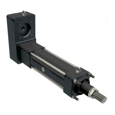
Tolomatic BCS10 Operator's manual

Tolomatic • URL: http://www.tolomatic.com • Email: [email protected] • Fax: (763) 478-8080 • Toll Free: 1-800-328-2174
Parts Sheet
3600-4011_18_BCS10ps
Model & Size
RTB _CS10 ____ SK_____ MR___
RTB BCS10 SN01 SK21.25 MRS23
*Replacement tube for BCS ordering method:
EXAMPLE:
Replacement Tube
RLS _CS10 ____ SK_____ MR___
RLS BCS10 SN01 SK21.25 MRS23
†Configurated code is the preferred ordering method:
EXAMPLE:
Replacement Lead Screw Motor CodeStroke LengthNut Style & Size
A/R = As Required
1
2
4
5
6
7
8
10
9
11
12
13
15
16
17
18
19
21
22
23
24
25
26
20
27
28 29
14
BCS10 Cylinder-Style
Screw-Drive Actuators
1-INCH
MODELS:
SN02 SN02(RP) SNA02
SNA02(RP) BNL08 BNL08(RP)
BN08 BN08(RP) SN01
SN01(RP) BN05 BN05(RP)
BCS10 MCS10
ITEM PART NO. DESCRIPTION
SN02
SN02RP(23 FRAME)
SN02RP(34 FRAME)
SNA02
SNA02RP(23 FRAME)
SNA02RP(34 FRAME)
BNL(L)08§
BN(L)08RP (23 FRAME)§
BN(L)08RP (34 FRAME)§
SN01
SN01RP(23 FRAME)
SN01RP(34 FRAME)
SN05
SN05RP(23 FRAME)
SN05RP(34 FRAME)
BN(L)08§
BN(L)08RP (23 FRAME)§
BN(L)08RP (34 FRAME)§
SN12
SN12RP (23 FRAME)
SN12RP (34 FRAME)
SN12
SN12RP (23 FRAME)
SN12RP (34 FRAME)
¡10910-1344 HEAD BOLT 8 8 8 8 8 8 8 8 8 8 8 8 8 8 8
4910-1344 HEAD BOLT 8 8 8 8 8 8 8 8 8
2. 0910-1482 NUT 5/16-24 1 1 1 1 1 1 1 1 1 1 1 1 1 1 1
4510-1104 NUT M8 X 1.0 1 1 1 1 1 1 1 1 1
4. 4510-1060 BALL BEARING,RADIAL 2 2 2 2 2 2 2 2 2 2 2 2 2 2 2 2 2 2 2 2 2 2 2 2
5. 0910-1382 HEAD,MACHINED 2 2 2 2 2 2 2 2 2 2 2 2 2 2 2
4510-1058 HEAD,MACHINED 2 2 2 2 2 2 2 2 2
†**6.
**
**
§**
§**
§**
**
**
**
**
**
**
**
**
**
**
**
**
0910-1385 LEAD SCREW, SN02 LMI A/R A/R
0510-1361 LEAD SCREW, SN02 RP(23 FRAME) A/R A/R
0510-1365 LEAD SCREW, SN02 RP(34 FRAME) A/R A/R
0910-1409 LEAD SCREW, BN(L)08 LMI A/R A/R
0510-1360 LEAD SCREW, BN(L)08 RP(23 FRAME) A/R A/R
0510-1364 LEAD SCREW, BN(L)08 RP(34 FRAME) A/R A/R
0910-1437 LEAD SCREW, SN01 LMI A/R
0510-1362 LEAD SCREW, SN01 RP(23 FRAME) A/R
0510-1366 LEAD SCREW, SN01 RP(34 FRAME) A/R
0510-1071 LEAD SCREW, SN05 LMI A/R
0510-1363 LEAD SCREW, SN05 RP(23 FRAME) A/R
0510-1367 LEAD SCREW, SN05 RP(34 FRAME) A/R
4510-1044 LEAD SCREW, SN12 LMI A/R
4510-1131 LEAD SCREW, SN12 RP(23 FRAME) A/R
4510-1134 LEAD SCREW, SN12 RP(34 FRAME) A/R
4510-1042 LEAD SCREW, SN25 LMI A/R
4510-1132 LEAD SCREW, SN25 RP(23 FRAME) A/R
4510-1135 LEAD SCREW, SN25 RP(34 FRAME) A/R
7. 0910-1430 BALL NUT 1 1 1
4510-1036 BALL NUT 1 1 1
8. 0910-1384 NUT BRACKET 1 1 1
4510-1048 NUT BRACKET 1 1 1
§Contact fac-
tory when
ordering a
replacement
low backlash
(BNL) Ball
Screw and Nut
** Specify
stroke when
ordering
# Available
with Repair
Kit #0510-
9130
¡When replac-
ing the head
bolts in actua-
tors manufac-
tured prior to
July 1, 2006,
the hole for
the head bolt
will need to be
drilled 0.4"
(10mm) deep-
er to accom-
modate the
longer screw
length.

Tolomatic • URL: http://www.tolomatic.com • Email: [email protected] • Fax: (763) 478-8080 • Toll Free: 1-800-328-2174
2 – Parts List BCS10/MCS10 Parts Sheet #3600-4011_18_BCS10ps
Drawing repeated for reference
BCS10 MCS10
ITEM PART NO. DESCRIPTION
SN02
SN02RP(23 FRAME)
SN02RP(34 FRAME)
SNA02
SNA02RP(23 FRAME)
SNA02RP(34 FRAME)
BNL(L)08§
BN(L)08RP (23 FRAME)§
BN(L)08RP (34 FRAME)§
SN01
SN01RP(23 FRAME)
SN01RP(34 FRAME)
SN05
SN05RP(23 FRAME)
SN05RP(34 FRAME)
BN(L)08§
BN(L)08RP (23 FRAME)§
BN(L)08RP (34 FRAME)§
SN12
SN12RP (23 FRAME)
SN12RP (34 FRAME)
SN12
SN12RP (23 FRAME)
SN12RP (34 FRAME)
*,** 9.
*,**
0510-1120 TUBE, MACHINED A/R A/R A/R A/R A/R A/RA/R A/R A/R A/R A/R A/R A/R A/R A/R
4510-1009 TUBE, MACHINED A/R A/R A/R A/R A/R A/R A/R A/RA/R
10.
0510-9051 NUT BRACKET ASSEMBLY 1 1 1
0510-9052 NUT BRACKET ASSEMBLY 1 1 1
0510-9053 NUT BRACKET ASSEMBLY 1 1 1
0510-9054 NUT BRACKET ASSEMBLY 1 1 1
4510-9044 NUT BRACKET ASSEMBLY 1 1 1
4510-9045 NUT BRACKET ASSEMBLY 1 1 1
11. 4510-1059 CUP,RETAINING RING 1 1 1 1 1 1 1 1 1 1 1 1 1 1 1 1 1 1 1 1 1 1 1 1
12. 0510-1019 RING,RETAINING 1 1 1 1 1 1 1 1 1 1 1 1 1 1 1 1 1 1 1 1 1 1 1 1
13. 0510-1012 PLUG 1 1 1 1 1 1 1 1 1 1 1 1 1 1 1
0515-1012 PLUG 1 1 1 1 1 1 1 1 1
14. 0912-1066 SHCS 1/4-20 X 1.75 LONG 1 1 1 1 1 1 1 1 1 1 1 1 1 1 1
4915-1173 SHCS M6 X 1.0 X 40 LONG 1 1 1 1 1 1 1 1 1
**#15.
0912-9000 (NDBB(M)CS10SK_) DUST BAND A/R A/R A/R A/R A/R A/RA/R A/R A/R A/R A/R A/R A/R A/R A/R A/R A/R A/R A/R A/R A/R A/R A/R A/R
16. 0910-1172 SHCS 6-32 X .50 LONG 4 4 4 4 4 4 4 4 4 4 4 4 4 4 4
4520-1046 SLHCS M4 X 0.7 X 16 LONG 4 4 4 4 4 4 4 4 4
17. 0515-1049 SET SCREW, 8-32 X .25 LONG 2 2 2 2 2 2 2 2 2 2 2 2 2 2 2
0610-1046 SET SCREW, M4 X 0.7 X 6 LONG 2 2 2 2 2 2 2 2 2
18. 0520-9015 BAND CLAMP ASSEMBLY 2 2 2 2 2 2 2 2 2 2 2 2 2 2 2
4515-9023 BAND CLAMP ASSEMBLY 2 2 2 2 2 2 2 2 2
19. 0520-1028 BAND CLAMP SLUG 2 2 2 2 2 2 2 2 2 2 2 2 2 2 2 2 2 2 2 2 2 2 2 2
20. 0910-1172 SHCS 6-32 X .50 LONG 4 4 4 4 4 4 4 4 4 4 4 4 4 4 4
4910-1172 SBHCS M4 X 0.7 X 16 LONG 4 4 4 4 4 4 4 4 4
21. 0910-1290 SBHCS 8-32 X .38 LONG 2 2 2 2 2 2 2 2 2 2 2 2 2 2 2
4910-1003 SLHCS M4 X 0.7 X 8 LONG 2 2 2 2 2 2 2 2 2
# 22. 4510-1002 END CAP,CARRIER 2 2 2 2 2 2 2 2 2 2 2 2 2 2 2 2 2 2 2 2 2 2 2 2
# 23. 4515-1012 BAND INSERT 2 2 2 2 2 2 2 2 2 2 2 2 2 2 2 2 2 2 2 2 2 2 2 2
#24.4520-1012SPRING 222222222222222222222222
# 25. 0910-1170 BEARING,ROD 2 2 2 2 2 2 2 2 2 2 2 2 2 2 2
4910-1170 BEARING,ROD 2 2 2 2 2 2 2 2 2
26. 0510-1025 CARRIER,MACHINED 1 1 1 1 1 1 1 1 1 1 1 1 1 1 1
4510-1049 CARRIER,MACHINED 1 1 1 1 1 1 1 1 1
27. 0912-1016 NUT 1/4-20 2 2 2 2 2 2 2 2 2 2 2 2 2 2 2
4510-1050 NUT M6 X 1.0 2 2 2 2 2 2 2 2 2
28.1004-1144WASHER 222222222222222222222222
29. 2006-1063 SFHCS 10-24 X .38 LONG 1 1 1 1 1 1 1 1 1 1 1 1 1 1 1
4410-1016 SFHCS M5 X 0.8 X 10 LONG 1 1 1 1 1 1 1 1 1
RTB _CS10 ____ SK_____ MR___
RTB BCS10 SN01 SK21.25 MRS23
*Replacement tube for BCS ordering method:
EXAMPLE:
Replacement Tube
RLS _CS10 ____ SK_____ MR___
RLS BCS10 SN01 SK21.25 MRS23
†Configurated code is the preferred ordering method:
EXAMPLE:
Replacement Lead Screw Motor CodeStroke LengthNut Style & Size
A/R = As Required
§Contact fac-
tory when
ordering a
replacement
low backlash
(BNL) Ball
Screw and Nut
** Specify
stroke when
ordering
# Available
with Repair
Kit #0510-
9130
¡When replac-
ing the head
bolts in actua-
tors manufac-
tured prior to
July 1, 2006,
the hole for
the head bolt
will need to be
drilled 0.4"
(10mm) deep-
er to accom-
modate the
longer screw
length.
1
2
4
5
6
7
8
10
9
11
12
13
15
16
17
18
19
21
22
23
24
25
26
20
27
28 29
14

Tolomatic • URL: http://www.tolomatic.com • Email: [email protected] • Fax: (763) 478-8080 • Toll Free: 1-800-328-2174
Parts Sheet #3600-4011_18_BCS10psParts Sheet #3600-4011_18_BCS10ps BCS10/MCS10 Instructions – 3
Christo-Lube® is a registered trademark of Lubrication Technology, Inc., www.lubricationtechnology.com
Loctite® is a registered trademark of the Loctite Corporation, www.loctite.com
INTRODUCTION
Begin with a clean work area. Be sure all parts are present and
have no visual damage or defects. The following tools are recom-
mended for proper disassembly and assembly (exact wrench
sizes will vary depending upon cylinder size):
Tin Snips
Allen Wrench Set
Open-end or Box Wrenches and/or Sockets
DISASSEMBLY INSTRUCTIONS
1. REMOVE CARRIER: Remove Bolts (#14), Washers (#28) and
Nuts (#27). Remove Carrier (#26) from Bracket (#8) by removing
Screw (#29). Remove Spring (#24), Band Insert (#23), and End
Cap (#22) by removing Screws (#20 and 21) at each end of
Carrier. Remove Bearing Rods (#25). Remove carrier (#26).
2. REMOVE DUST BAND: Loosen Clamp Slug (#19) holding Band
by loosening Set Screw (#17). Remove two Screws (#16) securing
Band Clamp Assembly (#18). Remove Band Clamp
Assembly (#18) from top of Slug, then remove Clamp Slug from
top of Band (next to Head). IMPORTANT NOTE: Edges of Dust
Band are SHARP — Use caution when handling to avoid injury!
Carefully pull the Dust Band (#15) from the Tube (#9) and through
the Nut Bracket Assembly (#10)
3. DISASSEMBLE UNIT.
Remove the four Bolts (#1) from both heads (5). Remove the
lock nut (2) from the “live side” of the lead screw. Remove the
“live side” head w/ bearing (4). Remove the Plug (#13) from the
“dead side” head. Push ring cup (#11) to expose Retaining
Ring (#12) and remove retaining ring from groove of Lead
Screw (#6). Remove ring cup and head w/ bearing. Slide lead
screw w/ nut bracket (#8) and Ball Nut (#7) out of Machined
Tube (#9).
A. Ball Nut Style: DO NOT REMOVE NUT BRACKET w/
BALL NUT FROM LEAD SCREW (balls will fall out).
B. Plastic Nut Style: Remove nut bracket w/ lead screw
nut from lead screw.
4. HEAD SUB-ASSEMBLY: If necessary, carefully remove
Bearings (#4) from both Heads (#5).
5. SUB-ASSEMBLIES:
Ball Nut Style: Caution is required if removal of nut is neces-
sary. Contact the factory for available parts and procedures.
Plastic Nut Style: Plastic nuts are factory pressed into the Nut
Bracket and cannot be removed. If nuts are worn, a new Nut
Bracket Assembly must be ordered.
ASSEMBLY INSTRUCTIONS
1. AREA PREPARATION: Ensure all parts are present and have
no visual damage or defects.
2. PREPARE HEAD SUB-ASSEMBLY: Carefully install Bearings (#4) in
both Heads (#5).
3. ASSEMBLE UNIT:
A. Ball Nut Style: Grease Lead Screw (#6) with Mobil HP
Multi-purpose grease. Install Lead Screw in machined
tube. Place Head (#5) on “dead” end of Lead Screw (non-
threaded end). Secure with Ring Cup (#11) and Snap
Ring (#12). NOTE: Make sure the Snap Ring is properly
seated in groove on the Lead Screw, then pull Ring Cup
over Snap Ring. Install second Head, and Nut (#2). Snug up,
but do not tighten the four Bolts (#1) on each Head. Place
an End Plug (#13) in the “dead” side Head.
B. Plastic Nut Style: Grease Screw (#6) with Christolube®
MCG405, assemble Nut Bracket to Screw with the Nut
end facing the “live” end (threaded end) of the Screw.
Install Screw in machined tube. Place Head on “dead”
end of Screw (non-threaded end). Secure with Ring Cup
(#11) and Snap Ring (#12). NOTE: Make sure the Snap
Ring is properly seated in groove on the lead Screw, then
pull Ring Cup over Snap Ring. Install second Head and
Nut (#2). Snug up, but do not tighten the four Bolts (#1)
on each Head. Place an End Plug (#13) in the “dead”
side Head.
4. INSTALL CARRIER: Thread one end of Band (#15) through
slot in Bracket (#8) and press down on Band (#15) to seat in
tube. Place Carrier (#26) on Tube and align with Nut Bracket.
Install Bearing Rods (#25). Secure Spring (#24), Band
Insert (#23), and End Cap (#22) in place by tightening
Screws (#20 and 21) with Loctite #242 to each end of Carrier.
Secure Carrier in Bracket by tightening Screws (#29) with
Loctite #242. Install Bolts (#14), Washers (#28) and Nuts (#27).
Snug up the bolts only. NOTE: “Snug” means no noticeable
end play by hand. If a wrench is applied to either end, both
ends will turn.
5. ALIGN HEADS: Place Carrier next to each Head then tighten
the four Head Bolts (#1) to assure proper alignment of Head
and Carrier. (¡When replacing the head bolts in actuators manu-
factured prior to July 1, 2006, the hole for the head bolt will
need to be drilled 0.4" [10mm] deeper to accommodate the
longer screw length.)
HEAD TORQUE REQUIREMENTS
Cylinder Size In-Lbs of Torque
1" 70-80
1-1/2" 100-110
2" 180-195
6. TRIM AND SECURE DUST BAND: Locate on one Head a
Slug (#19) and Band Clamp Assembly (#18). (NOTE: Width of
Slug should match dust Band width.) Tighten with Screw (#16)
and Loctite #242. Insert one end of Dust Band (#15) under
Band Clamp assembly and Slug until it is tight to the Head.
Install Set Screw (#17) into Band Clamp assembly and tighten
against Slug.
With tin snips, cut the end of the Band so it nearly butts to the
other Head. Place Clamp Slug (#19) on top of Band (next to
Head), then place Band Clamp Assembly (#18) over Slug.
Tighten to Head with two Screws (#16) and Loctite #242. Install
Set Screws (#17).
7. TEST PROCEDURE: The torque required to rotate the Lead
Screw (#6) should not exceed the following limits.
MAXIMUM BREAKAWAY REQUIREMENTS:
Cylinder Size Torque
1" 25 ounce-inches
1-1/2" 30 ounce-inches
2" 45 ounce-inches
Check and/or readjust unit to conform to specification
requirements. Retest.
8. CLEAN UNIT THOROUGHLY BEFORE INSTALLING.

Tolomatic • URL: http://www.tolomatic.com • Email: [email protected] • Fax: (763) 478-8080 • Toll Free: 1-800-328-2174
Parts Sheet #3600-4011_18_BCS10ps
4 – In-Line Mounting Parts List BCS10/MCS10
2
1
IN-LINE MOUNTING
IN-LINE MOUNTING WITH
GEARHEAD
ITEM PART NO. DESCRIPTION
MRB2XX
MRS 2XX
MRB34X
MRS34X
MRV2XX W/O SN01
MRV21X W/ SN01 (SN25)
GHK W/ MRB2XX
GHK W/ MRS2XX
GHJ30,31 W/ MRB3X
GHJ30,31 W/ MRS3X
GHJ20,21 W/ MRV2XX
GHJ20,21W/MRV2XX W/
SN01 (SN25)
1. 3410-9202 Motor Adapter Kit 1 1 1 1
3410-9149 Motor Adapter Kit 1 1 1 1
3410-9201 Motor Adapter Kit 1 1 1 1
4410-9202 Motor Adapter Kit - metric 1 1 1 1
4410-4149 Motor Adapter Kit - metric 1 1 1 1
4410-9201 Motor Adapter Kit - metric 1 1 1 1
2. 3600-9204 Coupler 1 1 1 1
3600-9213 Coupler 1 1 1 1
3600-9206 Coupler 1 1
3600-6163 Coupler 1 1
4520-9103 Coupler - metric 1 1 1 1
4520-9107 Coupler - metric 1 1
4520-9106 Coupler - metric 1 1
3600-6181 Coupler - metric 1 1
4520-9107 Coupler - metric 1 1
ITEM PART NO. DESCRIPTION
ALL BCS10
MODLES
FLOATING MOUNT
30. 0510-1009 Pin 1
31. 0910-1196 Clamp 1
32. 0910-1195 Bracket 1
33. 0910-1199 Screw 2
SWITCHES
34. SEE PAGE 6
35. 0910-1238 Switch Magnet 1
TUBE SUPPORTS
36. 4510-1010 Bracket 1
Inline Motor Mount
Tube Supports, Floating Mounts and Switches
Disassembly and Assembly Instructions
TUBE SUPPORTS
Follow cylinder assembly instructions through steps 5. Before
installing second cylinder Head (#5) in step 6, slide Tube
Support (#36) onto cylinder Tube (#9).
FLOATING MOUNT
Completely assemble cylinder. Place Pin (#30) flat side towards
Carrier (#26) and between the two center holes. Place Floating
Mount Clamp (#31) over Pin (#30) and secure to the Carrier
(#26) with Screws (#33) and Loctite® #242. Place Floating
Mount Bracket (#32) over Pin (#30) and hold in place with a
rubber band.
SWITCHES
On assembled cylinder, Secure Switch to open port side of
cylinder with a Hardware Kit (#34) clamp and screw. Cycle the
carrier over the Switch by hand to ensure that the carrier does
not hit the switch. See page 6 for additional switch information.
35
36
30
31
32
33
34
BCS10 OPTIONS
FLOATING
MOUNT
TUBE
SUPPORTS
SWITCHES
(Also see drawing on page 1)

Tolomatic • URL: http://www.tolomatic.com • Email: [email protected] • Fax: (763) 478-8080 • Toll Free: 1-800-328-2174
Parts Sheet #3600-4011_18_BCS10psParts Sheet #3600-4011_18_BCS10ps BCS10/MCS10 Reverse Parallel Mounting – 5
BCS10 MCS10
1:1 RATIO 2:1 RATIO 1:1 RATIO 2:1 RATIO
ITEM PART NO. DESCRIPTION
MRV21,22,23,24
MRS231,232,MRB21
MRB31,32
MRS341,342,343
MRV21,22,23,24
MRS231,232,MRB21
MRB31,32
MRS341,342,343
MRV21,22,23,24
MRS231,232,MRB21
MRB31,32
MRS341,342,343
MRV21,22,23,24
MRS231,232,MRB21
MRB31,32
MRS341,342,343
1. 3420-1640 SHCS, M5 X 0.8, 50 MM LONG, LOW HEAD, SST 1 1 1 1 1 1 1 1
3420-1639 SHCS, M5 X 0.8, 55 MM LONG, LOW HEAD, SST 1 1 1 1 1 1 1 1
2. 0601-1618 COVER, BCS10/B3S10-23 FRAME 1 1 1 1 1 1 1 1
0602-1618 COVER, BCS10/B3S10-34 FRAME 1 1 1 1 1 1 1 1
3. 0510-1109 BEARING, BALL, RADIAL, Ø.250 1 1 1 1 1 1 1 1 1 1 1 1 1 1 1 1
4. 0510-1112 TIMING BELT, 11.00-1/5-3/8 1 1 1 1 1 1 1 1
0510-1113 TIMING BELT, 13.00-1/5-3/8 1 1 1 1 1 1 1 1
5. 0520-1067 CLAMP COLLAR, Ø.688 1 1 1 1 1 1 1 1
6. 0515-1191 PULLEY, 18 TEETH, .38 WIDTH 1 1 1 1 1 1 1 1
0510-1110 PULLEY, 36 TEETH, .38 WIDTH 1 1 1 1 1 1 1 1
7.
3420-1255 PULLEY, 18 TEETH, .38 WIDTH 1 1 1 1 1 1 1 1
0515-1191 PULLEY, 18 TEETH, .38 WIDTH 1 1 1 1
0515-1192 PULLEY, 18 TEETH, .38 WIDTH 1 1 1 1
8. 0510-1111 TRANTORQ, Ø.250 1 1 1 1 1 1 1 1 1 1 1 1 1 1 1 1
9. 0510-1111 TRANTORQ, Ø.250 1 1 1 1
0515-1181 TRANTORQ, Ø.375 1 1 1 1
10. 3410-1229 BHCS, TORX, 10-24, 0.50, BLK 4 4 4 4 4 4 4 4
3420-1644 SHCS, M5 X 0.8, 12 MM LONG, LOW HEAD 4 4 4 4 4 4 4 4
11. 0601-1053 PLATE, MOTOR, 23 FRAME 1 1 1 1 1 1 1 1
0602-1057 PLATE, MOTOR, 34 FRAME 1 1 1 1 1 1 1 1
12. 0601-1608 HOUSING, BCS10/B3S10-23 FRAME 1 1 1 1 1 1 1 1
0602-1608 HOUSING, BCS10/B3S10-34 FRAME 1 1 1 1 1 1 1 1
13. 0601-1625 SCREW, #6 X .25, SELF-TAPPING, SST 8 8 8 8 8 8 8 8 8 8 8 8 8 8 8 8
14. 0601-1602 END CAP 2 2 2 2 2 2 2 2
0602-1602 END CAP 2 2 2 2 2 2 2 2
15. 2212-1098 SHCS, M5 X 0.8, 20 MM LONG, SST 4 4 4 4
2212-1099 SHCS, M5 X 0.8, 25 MM LONG, SST 4 4 4 4 4 4 4 4 4 4 4 4
REVERSE PARALLEL DISASSEMBLY INSTRUCTIONS
1. Remove End Cap’s (#14). Release tension on belt by breaking loose the
motor screws (#15).
2. Remove RP Cover (#2).
3. Remove both drive pulley (#7) and driven pulley (#6) from their respective
shafts. The belt (#4) will come off with the pulley’s.
4. Remove motor screws (#15) from the motor plate (#11), to remove the motor
from the RP Housing.
5. Remove the RP Housing (#12) from the head by removing screws (#10).
REVERSE PARALLEL ASSEMBLY INSTRUCTIONS
*Apply Loctite #242 to all screws upon installation
1. Install RP Housing (#12) to the head with cap screws (#10). Do not fully tight-
en the screws at this time and verify that the RP Housing can move with
respect to the head.
2. Temporarily install the cover (#2) with bearing (#3) onto the RP Housing posi-
tioning the bearing over the leadscrew shaft. Hold the cover in place while
tightening all of the screws (#10) that hold the RP Housing to the head.
3. Remove the cover (#2) and finish tightening all screws attaching the RP
Housing to the head.
4. Install the motor to the RP Housing with screws (#15). Do not tighten the
screws at this time.
5. Locate the belt (#4) over the pulleys and slide the drive (#7) and driven (#6)
pulleys over their respective shafts. Tighten each pulley to it’s shaft with
either trantorque or collar clamp. If trantorque, utilize torque wrench to apply
appropriate torque. 1/2" hex on trantorque apply 75 in-lbs. 5/8" hex on tran-
torque apply 100 in-lbs.
6. Verify that there is clearance between the inside of the RP Housing and each
pulley. Verify that the pulleys are aligned to each other.
7. Position the cover (#2) in mating slot of the RP Housing and install the SHCS
(#1) to hold in place. Take care not to overtighten. If the cover is deflected it
can interfere with the leadscrew.
8. Tension the belt by pulling the motor away from the drive shaft with appropri-
ate force from chart below. Tighten the motor screws while this force is
applied to the motor.
Motor Frame Tension Force
MRB23, MRS17/23 10 lbs
MRV23, MRS34 20 lbs
MRV34, MRB34 30 lbs
9. Install both end caps (#14) with the screws (#13) to finalize assembly.
10
15
8
6
3
4
2
1
579
11
14
12
13

3800 County Road 116, Hamel, MN 55340
http://www.Tolomatic.com • Email: Help@Tolomatic.com
Phone: (763) 478-8000 • Fax: (763) 478-8080 • Toll Free: 1-800-328-2174
8
© 2017 Tolomatic 201708081451
Information furnished is believed to be accurate
and reliable. However, Tolomatic assumes no
responsibility for its use or for any errors that may
appear in this document. Tolomatic reserves the
right to change the design or operation of the
equipment described herein and any associated
motion products without notice. Information in
this document is subject to change without notice.
6 – Switches BCS10/MCS10 Parts Sheet #3600-4011_18_BCS10ps
PERFORMANCE
THE NOTCHED
FACE OF THE
SWITCH INDICATES
THE SENSING
SURFACE AND
MUST FACE
TOWARD THE
MAGNET.
THE NOTCHED
GROOVE IN THE
ACTUATOR
INDICATES THE
GROOVE TO
INSTALL THE
SWITCH. CONTACT
TOLOMATIC IF
SWITCHES ARE
REQUIRED ON
ANOTHER SIDE OF
ACTUATOR.
0
50
100
150
200
0100 200 300 400 500
VOLTAGE A.C. or D.C.
CURRENT D.C (mA)
REED FORM A
R
E
E
D
F
O
R
M
C
TEMP. vs CURRENT, DC REED VOLTAGE DERATING, DC REEDTEMP. vs CURRENT, AC REED
0
100
200
300
400
500
600
020406080 100 120 140 160
LOAD CURRENT (mA)
OPERATING TEMPERATURE (F)
REED FORM C
REED FORM A
0
200
400
600
800
1000
020406080 100 120 140 160
LOAD CURENT (mA)
OPERATING TEMPERATURE (F)
TRIAC
RT & RM DC REED, FORM A
BT & BM DC REED, FORM C
CT & CM AC REED, TRIAC
TT & TM HALL-EFFECT, SOURCING, PNP
KT & KM HALL-EFFECT, SINKING, NPN
REED
SWITCH
LOAD
BROWN
BLUE
(-) (-)
(+)(+)
REED
SWITCH
LOAD
BROWN
BLUE
(-)
(-)
(+)(+)
OR
AC
COM
LOAD
INPUT
TRIAC
SWITCH
120V
ac
Max.
MOV
BROWN
BLUE
REED
SWITCH
COMMON
NORMALL
Y CLOSED
NORMALLY OPEN
BROWN
BLACK
BLUE
HALL-EFFECT
SOURCING
SWITCH
BLACK
LOAD
BROWN
BLUE (-)
(+)
(-)
(+)
HALL-EFFECT
SINKING
SWITCH
BROWN
BLACK
BLUE (-)
(+)
(-)
(+)
LOAD
WIRING DIAGRAMS INSTALLATION INFORMATION
Some actuators may
require switch mount-
ing on a specific side
of the assembly. Call
Tolomatic for details.
Female Connector 5M
SWITCHES
There are 10 sensing choices: DC reed, form A (open) or form C (open or
closed); AC reed (Triac, open); Hall-effect, sourcing, PNP (open); Hall-effect,
sinking, NPN (open); each with either flying leads or QD (quick disconnect).
Commonly used to send analog signals to PLC (programmable logic
controllers), TLL, CMOS circuit or other controller device. These switches are
activated by the actuator’s magnet.
Switches contain reverse polarity protection. QD cables are shielded; shield
should be terminated at flying lead end.
If necessary to remove factory installed switches, be sure to reinstall on the
same of side of actuator with scored face of switch toward internal magnet.
**
WARNING
: Do not exceed power rating (Watt = Voltage X Amperage). Permanent damage to sensor will occur.
*QD = Quick Disconnect; Male coupler is located 6" [152mm} from sensor,
Female coupler to flying lead distance is 197" [5m] also see Cable Shielding specification above
REPLACEMENT OF QD SWITCHES MANUFACTURED BEFORE JULY 1, 1997:
It will be necessary to replace or rewire the female end coupler.
CAUTION: DO NOT OVER TIGHTEN SWITCH HARDWARE WHEN INSTALLING!
CURRENT
Quick disconnect
Wiring
BROWN
BLACK
BLUE
+
-
SIGNAL
OLD
Quick disconnect
Wiring
BROWN
BLACK
BLUE
+
-
SIGNAL
†Shielded from the female quick disconnect coupler to the flying leads. Shield should be terminated at flying lead end.
§
Maximum current 500mA (not to exceed 10VA) Refer to Temperature vs. Current graph and Voltage Derating graph
§§
Maximum current 250mA (not to exceed 3VA) Refer to Temperature vs. Current graph and Voltage Derating graph
Reed Switch Life Expectancy: Up to
200,000,000 cycles (depending on load cur-
rent, duty cycle and environmental conditions)
DC REED, AC REED (TRIAC)
AND HALL-EFFECT
QUICK-DISCONNECT
COUPLER - MALE END
QUICK-DISCONNECT
COUPLER - FEMALE END
SPECIFICATIONS
REED DC REED AC HALL-EFFECT DC
ORDER CODE
RT RM BT BM CT CM TT TM KT KM
LEAD 5m QD* 5m QD* 5m QD* 5m QD* 5m QD*
CABLE SHIELDING Unshielded Shielded† Unshielded Shielded† Unshielded Shielded† Unshielded Shielded† Unshielded Shielded†
SWITCHING LOGIC "A" Normally Open "C" Normally Open or Closed Triac Normally Open PNP (Sourcing) Normally
Open NPN (Sinking) Normally Open
MECHANICAL CONTACTS Single-Pole Single-Throw Single-Pole Double-Throw Single-Pole Single-Throw NO, These Are Solid State Components
COIL DIRECT Yes Yes Yes —
POWER LED None None None None None
SIGNAL LED Red Red Red
OPERATING VOLTAGE 200 Vdc max. 120 Vdc max. 120 Vac max. 5 - 25 Vdc
OUTPUT RATING — — 25 Vdc, 200mA dc
OPERATING TIME 0.6 msec max.
(including bounce)
0.7 msec max.
(including bounce) —< 10 micro sec.
OPERATING TEMPERATURE -40°F [-40°C] to 158°F [70°C] 0°F [-18°C] to 150°F [66°C]
RELEASE TIME 1.0 msec. max. — —
ON TRIP POINT — — 150 Gauss maximum
OFF TRIP POINT — — 40 Gauss minimum
**POWER RATING (WATTS) 10.0
§
3.0
§ §
10.0 5.0
VOLTAGE DROP 2.6 V typical at 100 mA NA — —
RESISTANCE 0.1 Ω Initial (Max.) — —
CURRENT CONSUMPTION —1 Amp at
86°F [30°C]
0.5 Amp at
140°F [60°C] 200 mA at 25 Vdc
FREQUENCY —47 - 63 Hz —
CABLE MIN.
BEND
RADIUS
STATIC 0.630" [16mm]
DYNAMIC Not Recommended
REPLACEMENT OF QD SWITCHES
MANUFACTURED BEFORE JULY 1, 1997:
It will be necessary
to replace or
rewire the
female end
coupler.
3. SWITCHES
NOTE: Form A Reed Switches should not be used in TTL logic cir-
cuits. A voltage drop caused by the L.E.D. indicator will result.For
applications where TTL circuits are used, please contact the factory.
WARNING: An ohmmeter is recommended for testing Reed
Switches. NEVER use an incandescent light bulb as a high current
rush may damage the switch.
Reed and TRIAC switches are only recommended for signalling
position, not directly powering solenoids. For shifting a solenoid, a
relay or resistor is recommended between it and the Reed Switch.
Switch ratings must not be exceeded at any time.
NOTE: For Hall Effect Switch Magnet, be sure the S pole of the mag-
net (indicated with black dot) is facing toward the switch (down).
Switch Ordering NOTES:
To order field retrofit switch and hardware kits for all Tolomatic actuators:
SW (Then the model and bore size, and type of switch required)
Example: SW BCS10 RT
(Hardware and Form A Reed switch with 5 meter lead for 1" size
BCS actuator)
Mounting hardware is required if replacing switch for any actuator
manufactured before 7/1/97
SWITCH KIT
34.
CONFIG. CODE ORDERING
Mounting Hardware & FE conn. included
CODE
DESCRIPTION
BT Switch Only, Reed, Form C, 5m
BM Switch Only, Reed, Form C, Male Conn.
RT Switch Only, Reed, Form A, 5m
RM Switch Only, Reed, Form A, Male Conn.
CT Switch Only, Triac, 5m
CM Switch Only, Triac, Male Conn.
KT Switch Only, Hall-effect, Sinking, 5m
KM
Switch Only, Hall-effect, Sinking, Male Conn.
TT Switch Only, Hall-effect, Sourcing, 5m
TM Switch Only, Hall-effect, Sourcing, Male Conn.
NOTE: When ordered by Config. Code Female connector & all mounting hardware
is
included
This manual suits for next models
1
Table of contents
Other Tolomatic Controllers manuals
Tolomatic
Tolomatic TRS Series User manual
Tolomatic
Tolomatic ServoWeld CSW Owner's manual
Tolomatic
Tolomatic IMA-S Series User manual
Tolomatic
Tolomatic ACS Manual
Tolomatic
Tolomatic MXP16P Series User manual

Tolomatic
Tolomatic ACS Manual
Tolomatic
Tolomatic IMA Series User manual
Tolomatic
Tolomatic Axidyne AXIOM PLUS PV Series User manual
Tolomatic
Tolomatic 3604-9651 Manual
Tolomatic
Tolomatic SmartActuator Series User manual
