Tolomatic BC4 Series User manual

Parts Sheet
6900-4002_18_BC410ps-OBS
QTY.
ITEM
PART NO. or
CONFIG. CODE
DESCRIPTION
BC4(L)10
U.S. Standard
BC4(L)M10 Metric
Taper Heads
BC4(L)M10 Metric
Parallel Heads
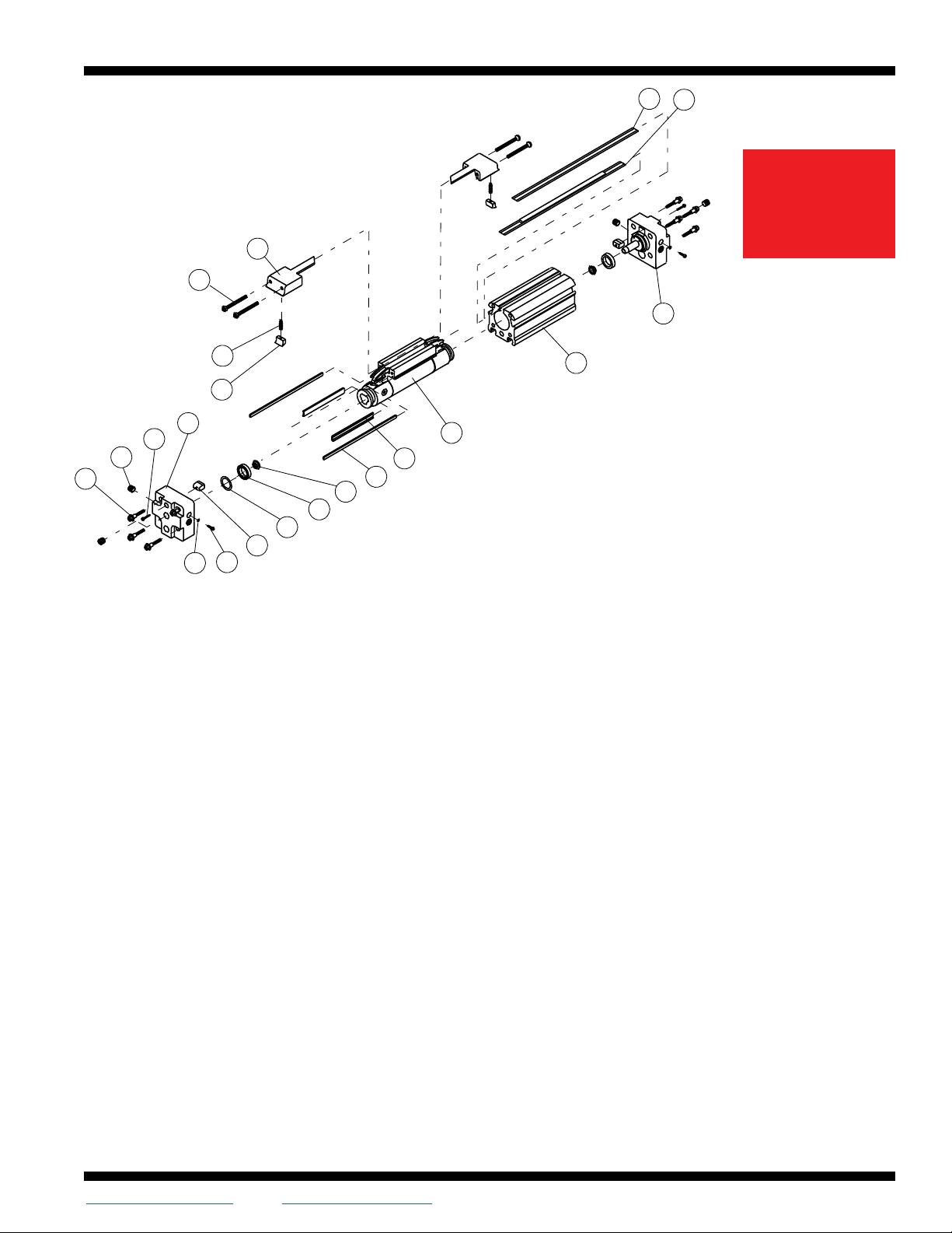
1
6910-9015 Left Head Assy. US Std. 1 – –
7910-9000 Left Head Assy. Metric Taper –1–
8910-9000 Left Head Assy. Metric Parallel – – 1
231207-1027
Socket Head Cap Screw US Std.
2 – –
4,54415-1024
Socket Head Cap Screw Metric
– 2 2
3
31014-1065 Pipe Plug 4 – –
44910-1002 Pipe Plug Metric Taper – 4 –
55910-1006 Pipe Plug Metric Parallel – – 4
740910-1344 Head Bolt US Std. 8 – –
4910-1344 Head Bolt Metric – 8 8
5
1,2,3,4,50910-1178
O-Ring 2 2 2
63,4,50910-1177 Cushion Needle 2 2 2
730910-1343 Band Clamp 2 – –
4,54910-1343 Band Clamp, Metric – 2 2
81,20910-1160 O-Ring 2 2 2
91,20910-1206 U-Cup 2 2 2
10 1,20910-1184 Cushion Seal 2 2 2
11 16910-1029 Wiper, Carrier 2 2 2
16910-1053 Wiper, Carrier, LCU 2 2 2
1 Repair Kit: Parts contained in Repair Kit RKBC4(L)(M,MM)10SK_ _ _
2Seal Kit: Parts contained in Seal Kit #6910-9022
3 Head Assy.: Parts contained in Head Assembly #6910-9015 & 6910-9016
4 Head Assy.: Parts contained in Head Assembly #7910-9000 & 7910-9001
5 Head Assy.: Parts contained in Head Assembly #8910-9000 & 8910-9001
6
After configuration code add: SK_ _ _(note: the letters SK indicate stroke, follow these let-
ters with the stroke length in decimal inches.) If the actuator has the dual carrier option add
the code DC_ _ _(note: follow the letters DC with the distance between the carriers in
decimal inches.)
7 NOTE: When replacing the head bolts in actuators manufactured prior to July 1, 2006,
the hole for the head bolt will need to be drilled 0.4”(10mm) deeper to accommodate the
longer screw length.
8 NOTE: Repair Kits include 3 sets of color coded Slot Bearings. Select the same color
combinations as originally installed.
BC4 Series™Band Cylinder®
BC410, BC4M10, BC4MM10
BC4L10, BC4LM10, BC4LMM10
1"(25 mm) Bore
QTY.
ITEM
PART NO. or
CONFIG. CODE
DESCRIPTION
BC4(L)10
U.S. Standard
BC4(L)M10 Metric
Taper Heads
BC4(L)M10 Metric
Parallel Heads
812.
16910-1003 Bearing, Slot, Blue 2 2 2
16910-1050 Bearing, Slot, Blue 2 2 2
16910-1004 Bearing, Slot, Natural 2 2 2
16910-1051 Bearing, Slot, Natural 2 2 2
16910-1005 Bearing, Slot, Black 2 2 2
16910-1052 Bearing, Slot, Black 2 2 2
13
16910-9025 Carrier/Piston Assy 1 – –
16910-9028 Long Carrier/Pist Assy 1 – –
1 7910-9025 Carrier/Pist. Assy, Metric – 1 1
1 7910-9028 Long Carrier/Pist Assy, Metric – 1 1
14
6RTBBC4(L)10 Replacement Tube (6910-1010)
specify stroke
A/R – –
6RTBBC4(L)M10
– A/R –
6RTBBC4(L)MM10
– – A/R
15
6910-9016 Right Head Assy. US STd. 1 – –
7910-9001 Right Head Assy. Metric Taper –1–
8910-9001
Right Head Assy. Metric Parallel
– – 1
16
1,6NSBBC410 Replacement Seal Band(6910-
1046) specify stroke
A/R – –
1,6NSBBC4M10 – A/R –
1,6NSBBC4MM10
– – A/R
1,6NSBBC4L10 Replacement Seal Band; Long
Carrier(6910-1064) specify
stroke
A/R – –
1,6NSBBC4LM10 – A/R –
1,6NSBBC4LMM10
– – A/R
17
1,6NDBBC410 Replacement Dust Band(6910-
1045) specify stroke
A/R – –
1,6NDBBC4M10 – A/R –
1,6NDBBC4MM10
– – A/R
1,6NDBBC4L10 Replacement Dust Band; Long
Carrier(6910-1065) specify
stroke
A/R – –
1,6NDBBC4LM10 – A/R –
1,6NDBBC4LMM10
– – A/R
18 16910-1025 Screw, Pan 4 4 4
19 16910-1006 End Cap 2 2 2
20 10605-1008 Spring, Compression 2 2 2
21 16910-1007 Wiper, Band 2 2 2
18
1
2
3
4
5 6
7
8
9
10
11
12
13
14
19
15
20
21
17 16
DISCONTINUED
PRODUCT STYLE
OR SIZE. PARTS
SHEET IS FOR
REPAIR USE ONLY.
Parts Sheet #6900-4002_18_BC410ps-OBS
BC4(L)10, BC4(L)M10, BC4(L)MM10 Instructions – 2
Drawing repeated for reference
18
1
2
3
4
5 6
7
8
9
10
11
12
13
14
19
15
20
21
17 16
CYLINDER DISASSEMBLY INSTRUCTIONS FOR INSTALLATION OF
REPAIR KITS ONLY
1. Remove Band Cylinder from machinery.
2. Remove any foot mounting hardware external shock absorbers or switches if present.
Remove the four Head Bolts(#4) and loosen the SHCS(#2) on each cylinder Head(#1, #15).
Remove Heads.
3. Remove Screws(#18) from End Caps(#19) and slide End Caps off Carrier(#13). Remove top
Dust Band(#17). Remove the Carrier Assembly(#13) from the Tube(#14).
4. Dislodge the inner Sealing Band(#16) from its groove by gently pressing down on the band
with an O-ring Pick or similar tool.(When doing so, take care that NO SCRATCHES are made
in the tube bore slot.) Remove Sealing Band(#16).
CYLINDER ASSEMBLY INSTRUCTIONS
1. CLEAN AND LUBRICATE
Thoroughly clean all components, particularly the tube bore slot and bands. Thoroughly lubri-
cate the tube with RheoGel TEK664 grease. Apply light coat of grease to Sealing Band(#16)
and Dust Band(#17).
2. ASSEMBLE SEALING BAND
CAUTION: Metal edges of Sealing Band are sharp. Exercise caution
to avoid injury to yourself of the Band and Tube when inserting.
Carefully install Sealing Band(#16) by passing it sideways though the slot in the tube. Position
Sealing Band, rubber up, on the bottom of the tube with equal length of band extending out
both ends of the tube.
3. INSTALL PISTON/CARRIER ASSEMBLY
Lubricate and install new U-Cups(#9)(lip seals facing out) onto Piston ends(#13). Lubricate
and install new Cushion Seals(#10)(small end facing out) into Piston ends and rotate to seat
them in their grooves.
NOTE: If the cylinder will be used with optional shock absorber packages, do not install the
Cushion Seals. Doing so will adversely affect
shock performance.
4. INSTALL CARRIER BEARINGS
Repair Kits include 3 sets of color coded Slot Bearings(#12). Select the same color combina-
tion Slot Bearings as originally installed. Insert
Piston/Carrier Assembly(#13) and Slot Bearings into
tube and manually push the Carrier the full length of the
Tube(#14). As this is done check that the fit of the Carrier is firm.
NOTE: A tight fit will result in higher cylinder break-
away. Use your own discretion in determining perfor-
mance requirements for your application. It fit is insufficient, select the
next size bearing, larger or smaller as needed. Repeat until
fit is correct.
Remove Piston/Carrier Assembly(#13) and place a small amount of RheoGel TEK664 into the
Cushion Seals(#10) then fill both sides of Piston completely with grease. Install Piston/Carrier
Assembly into Tube(#14) with Magnet facing the die mark that is located in the
switch groove and feed the Sealing Band(#16) between the Piston
and the bracket.
NOTE: Take care that the U-Cup(#10) is not cut as the first end of the Piston is inserted into
the Tube.
a. Manually slide Piston/Carrier Assembly(#13) the length of the Tube(#14) to seat the
Sealing Band(#16) into the groove until end of piston is present at other end of tube. As
the end of the Piston exits the Tube, grease should be present on the Piston. If not, the
tube was not properly greased. Wipe off any excess grease. DO NOT REMOVE
THE PISTON FROM THE TUBE, doing so will require installing new sealing band. Leaving
the piston in place, proceed to(b.) below.
b. The Sealing Band is intentionally cut longer than the tube to elim-
inate indentations caused when U-cup on piston assembly
enters the tube to seat the sealing band. To remove these indentations,
carefully pull the Sealing Band(#16) out the end of the tube where the piston was first
inserted to reveal indentation(s) in the
band caused by the U-cup. Inspect the band and cut to remove
all indentations.
5. TRIM SEALING BAND
With a razor blade, remove rubber from extended band until flush with the end of tube. With tin
snips, trim band to length indicated.
Cylinder Size Trim Length From Tube
1”(25 mm) .656” (16.7 mm)(Tolerance of +/- .032”)
6. INSTALL HEADS
Lubricate and install new O-Rings(#8) onto Heads(#1, #15). Remove Cushion Needle
Valve(#6) and lubricate and install new O-Rings(#5) onto Cushion Needle Valves. Insert
Cushion Needle Valves(#6) back into Heads(#1, #15). Insert Heads into Tube(#14) using a
slight rocking motion. DO NOT TWIST. Twisting the Head during installation may cut the O-Ring
resulting in excessive leakage during operation.
NOTE: When inserting heads, make sure band does not get pushed backwards into tube.
Rubber on band must remain flush to the tube after head installation.
Install Head Bolts(#4) into Heads(#1, #15).(†When replacing the head bolts in actuators
manufactured prior to July 1, 2006, the hole for the head bolt will need to be drilled 0.4”
[10mm] deeper to accommodate the longer screw length.)
Torque Head Bolts(#4) to 100-110 in.-lbs(11.30-12.43 Nm).
7. SINGLE END PORT HEADS(Optional)
Grease and install O-Ring into gland. Procedure is now the same as for standard Heads.
DISCONTINUED
PRODUCT STYLE
OR SIZE. PARTS
SHEET IS FOR
REPAIR USE ONLY.

Parts Sheet #6900-4002_18_BC410ps-OBS
BC4(L)10, BC4(L)M10, BC4(L)MM10 Instructions – 3
Drawing repeated for reference
18
1
2
3
4
5 6
7
8
9
10
11
12
13
14
19
15
20
21
17 16
8. INSTALL DUST BAND
Clean Dust Band(#17) thoroughly with a clean cloth. Remove any rubber residue on the solid
steel surface with a razor blade. Strip rubber from steel on end of Dust Band(#17) flush with
the end of the Tube. With a tin snips, trim Band to the proper length.
Cylinder Size Trim Length From Tube
1”(25 mm) .656” (16.7 mm)(Tolerance of +/- .032”)
Insert trimmed Band into Head. Position Band above Band Clamp(#7). Tighten screw(#2) and
press into groove in Tube.
9. INSTALL END CAPS
Lightly lubricate the Band Wiper(#21). Place a Spring(#20) into the hole of the Band Wiper
and insert the Band Wiper into the End Cap(#19). Compress the Band Wiper and insert the
End Cap onto the Carrier(#13). While pressing down on the End Cap tighten End Cap fasten-
ers(#18).
NOTE: The top surface of the End Cap must be below the top surface of the Carrier.
Work the slack out of both the Sealing Band(#16) and Dust Band(#17) by moving the
Carrier by hand, from the Head with the Bands retained to the opposite Head. Trim rubber, cut
to length and secure the free end of Bands as described in steps 5 and 8.
CAUTION: Improper cut length of Band may introduce slack into Band when free end is
secured.
10. CHECK ASSEMBLY
Run the Carrier(#13) back and forth along the full stroke to make certain the cylinder is properly
assembled before applying air. Before mounting cylinder back in application, check the cylin-
der’s internal cushions.(If optional shock absorber kits are being used, this step can be elimi-
nated as Cushion Seals(#10) were not installed.) Push the Carrier(#13) to one end. You
should feel the Cushion decelerate the Carrier before the Cushion bottoms out. If the Carrier
slams into the end of the cylinder, either the Cushion Seals have not been properly installed or
the Cushion Needle Valve(#6) is adjusted too far out.
11. REMOUNT THE CYLINDER ONTO MACHINERY
OPTIONAL ACCESSORY ASSEMBLY INSTRUCTIONS
1. SHOCK
ABSORBERS
Using Loctite #242 screw
Impact Bolts(#70) into Shock Stop
Plate(#71) and Shock Stop Plate onto
Carrier. Secure Shock Mounting
Plate(#69) to Heads with SHCS(#67)
and Loctite #242. Screw the Shock
Absorber(#68) into the Shock Mounting Plate.
Attach the cylinder to air lines and under low pressure
cycle the Carrier to one end of the cylinder. Adjust the Shock
Absorber nearest the Carrier to bottom out the Shock at its fullest
stroke. Then back out the Shock one full turn and tighten the Jam Nut.
Repeat for the other end of the cylinder.
2. FOOT MOUNTS
Apply Loctite #242 to Screws(#65) and secure Foot Mount(#64) to each Head.
3. TUBE SUPPORTS
Four T Nuts(#61) are required on the bottom of Tube. Tube Supports should be secured
at the required distances determined for the application to prevent Tube deflection. Apply
Loctite #242 to Screws(#63) and secure Tube Supports(#62) to tube aligning holes in T
Nuts with holes in Tube Supports.
4. FLOATING MOUNT
Place Pin(#73), flat side towards carrier, between the two center holes as shown. Place
Floating Mount Clamp(#74) over pin and secure to the Carrier with Screws(#75) and
Loctite #242. Place Floating Mount Bracket
(#76) over pin.
5. SWITCHES
NOTE: Form A Reed Switches should not be used in TTL logic circuits.A voltage drop
caused by the L.E.D. indicator will result.For applications where TTL circuits are used, please
contact the factory.
WARNING: An ohmmeter is recommended for testing Reed Switches. NEVER use an
incandescent light bulb as a high current rush may damage the switch.
Reed and TRIAC switches are only recommended for signalling position, not directly powering
soleniods. For shifting a solenoid, a relay or resistor is recommended between it and the Reed
Switch. Switch ratings must not be exceeded at any time.
Christo-Lube
®
is a registered trademark of Lubrication Technology, Inc., www.lubricationtechnology.
com
Loctite
®
is a registered trademark of the Loctite Corporation, www.loctite.com
DISCONTINUED
PRODUCT STYLE
OR SIZE. PARTS
SHEET IS FOR
REPAIR USE ONLY.

Parts Sheet #6900-4002_18_BC410ps-OBS
BC4(L)10, BC4(L)M10, BC4(L)MM10 Instructions – 4
4 – Options BC4(L)10, BC4(L)M10, BC4(L)MM10
QTY.
ITEM
PART NO.
DESCRIPTION
BC410
U.S. Standard
BC4M10 Metric
Taper Rc Heads
BC4M10 Metric
Parallel G Heads
TUBE SUPPORTS1
KIT16910-9002
Tube Support Kit1US Standard
A/R – –
7910-9002 Tube Support Kit1Metric – A/R A/R
61
3410-1013 T-Nut US Std.
4 – –
4410-1013 T-Nut Metric
–4 4
62
6910-1013 Bracket, Tube Support
1 1 1
63
6910-1022
Flat Head Screw 4 – –
4410-1016
Flat Head Screw(Metric) –4 4
FOOT MOUNT
KIT26910-9003 Foot Mount Kit2US Standard A/R – –
7910-9003 Foot Mount Kit2Metric – A/R A/R
64
6910-1066
Foot Mount 2 2 2
65
0915-1016
Socket Head Screw 2 – –
4910-1004
Socket Head Screw(Metric) –2 2
SINGLE END PORTING
66
6910-9018 Head Assy, Single End Prtg
1 – –
7910-9006 Head Assy, Single End Prtg
–1–
8910-9002 Head Assy, Single End Prtg
– – 1
SHOCK ABSORBERS5
QTY.
ITEM
PART NO.
DESCRIPTION
BC410
U.S. Standard
BC4M10 Metric
Taper Rc Heads
BC4M10 Metric
Parallel G Heads
KIT36910-9024
Shock Mount
Kit3(Hardware Only)
US Standard
Metric
Shock
Absorber
Kit4
Heavy
Duty
US Standard
Metric
Light
Duty
US Standard
Metric
A/R – –
7910-9024 – A/R A/R
KIT4
6910-9020 A/R – –
7910-9020 – A/R A/R
6910-9005 A/R – –
7910-9005 – A/R A/R
67
0707-1010
Socket Head Screw 4 – –
4910-1004
Socket Head Screw(Metric) –4 4
68
0910-1480
Heavy Duty Shock 1 – –
4910-1338
Heavy Duty Shock(Metric) –1 1
0910-1479
Light Duty Shock 1 – –
4910-1337
Light Duty Shock(Metric) –1 1
69
6910-1017 Shock Mounting
Plate
US Standard
Metric
1 – –
7910-1017
–1 1
70
6910-1024
Shock Impact Bolt 2 2 2
71
6910-1019 Shock Stop Plate US Standard
Metric
1 – –
7910-1019
–1 1
72
0915-1016
Socket Head Screw 4 – –
4910-1004
Socket Head Screw(Metric) –4 4
FLOATING MOUNT
KIT 6910-9004
Floating Mount Kit US Standard
1 – –
7910-9004 Floating Mount Kit Metric – 1 1
73
6910-1021
Floating Mount Pin 1 1 1
74
6910-1059
Floating Mount Clamp 1 1 1
75
0801-1198
Socket Head Screw 4 – –
6910-1060
Socket Head Screw(Metric) –4 4
76
6910-1020
Floating Mount Bracket 1 1 1
SWITCHES
77
CONFIG. CODE ORDERING
Mounting Hardware & FE conn. included
CODE
DESCRIPTION
BT
Switch Kit, Reed, Form C, 5m
BM
Switch Kit, Reed, Form C, Male Conn.
RT
Switch Kit, Reed, Form A, 5m
RM
Switch Kit, Reed, Form A, Male Conn.
CT
Switch Kit, Triac, 5m
CM
Switch Kit, Triac, Male Conn.
KT
Switch Kit, Hall-effect, Sinking, 5m
KM
Switch Kit, Hall-effect, Sinking, Male Conn.
TT
Switch Kit, Hall-effect, Sourcing, 5m
TM
Switch Kit, Hall-effect, Sourcing, Male Conn.
NOTE: When ordered female connector & all mounting hardware is included
79 0510-1018 Shock Stop Spacer 2 2 2
Service Parts Ordering NOTES:
1A minimum of 2(two) Tube Supports required per cylinder
2Foot Mount Kit contains two foot mount brackets and
mounting hardware
3Shock Mount Kit contains one set of mounting hardware only
4Shock Absorber Kit contains one Shock Absorber and
mounting hardware
5Standard end-of-stroke shock absorbers are designed to oper-
ate without the assistance of the standard band cylinder cushion.
To ensure proper shock absorber performance, make sure the air
cushion is disabled.
A/R = As Required
Switch Ordering NOTES:
To order field retrofit switch and hardware kits for all Tolomatic actuators:
SW(Then the model and bore size, and type of switch required)
Example: SWB C 410 RT
(Hardware and Form A Reed switch with 5 meter lead for 1" bore BC4
band cylinder)
65
64
63 62
61
77
68
67
79
69 66
70
76
72
73 74 75
71
Shock
Stop Plate
Floating
Mount
Shock
Absorber
Tube
Support
Switches
Foot
Mount
DISCONTINUED
PRODUCT STYLE
OR SIZE. PARTS
SHEET IS FOR
REPAIR USE ONLY.

Parts Sheet #6900-4002_18_BC410ps-OBS
BC4(L)10, BC4(L)M10, BC4(L)MM10 Switches / Maintenance – 5
3800 County Road 116, Hamel, MN 55340 USA
http://www.Tolomatic.com • Email: Help@Tolomatic.com
Phone: (763) 478-8000 • Fax: (763) 478-8080 • Toll Free: 1-800-328-2174
© 2021 Tolomatic 202112070913
All brand and product names are trademarks or registered trademarks of their
respective owners. Information in this document is believed accurate at time of print-
ing. However, Tolomatic assumes no responsibility for its use or for any errors that
may appear in this document. Tolomatic reserves the right to change the design or
operation of the equipment described herein and any associated motion products
without notice. Information in this document is subject to change without notice.
Visit www.tolomatic.com for the most up-to-date technical information
LUBRICATION AND MAINTENANCE
All Tolomatic BC4 Band Cylinders are prelubricated at the factory. To ensure maximum cylinder life,
the following guidelines should be followed.
1. Filtration
We recommend the use of dry, filtered air in our products.“Filtered air” means a level of 10
Micron or less. “Dry” means air should be free of appreciable amounts of moisture. Regular
maintenance of installed filters will generally keep excess moisture in check.
2 External Lubricators(optional)
The factory prelubrication of Tolomatic Band Cylinders will provide optimal performance with-
out the use of external lubrication. However, external lubricators can further extend service life
of pneumatic actuators if the supply is kept constant.
Oil lubricators,(mist or drop) should supply a minimum of 1 drop per 20 standard cubic feet
per minute to the cylinder. As a rule of thumb, double that rate if water in the system is sus-
pected. Demanding conditions may require more lubricant.
If lubricators are used, we recommend a non-detergent, 20cP @ 140˚F 10-weight lubricant.
Optimum conditions for standard cylinder operation is +32˚ to +150˚F(+0˚ to 65.5˚C).
NOTE: Use of external lubricators may wash away the factory installed lubrication. External
lubricants must be maintained in a constant supply or the results will be a dry actuator prone
to premature wear.
3. Sanitary environments
Oil mist lubricators must dispense “Food Grade” lubricants to the air supply. Use fluids with
ORAL LD50 toxicity ratings of 35 or higher such as Multitherm
®
PG-1 or equivalent.
Demanding conditions can require a review of the application.
4. Bearing lubrication
The bearing system is prelubricated at the factory with a high quality RheoGel TEK664 grease.
Relubrication is recommended every .5-1 million cycles using RheoGel TEK664 grease.
5. Cushion Adjustment
Adjust the cushion needles in the cylinder heads carefully to obtain a smooth, hesitation free deceler-
ation for your particular application. If there are questions on proper adjustment, please consult
Tolomatic, Inc.
Some actuators may require
switch mounting on a spe-
cific side of the assembly.
Call Tolomatic for details.
REPLACEMENT OF QD SWITCHES
MANUFACTURED BEFORE JULY 1, 1997: It will be
necessary to
replace or rewire
the female end
coupler.
Female Connector 5M
DISCONTINUED
PRODUCT STYLE
OR SIZE. PARTS
SHEET IS FOR
REPAIR USE ONLY.
This manual suits for next models
6
Table of contents
Other Tolomatic Industrial Equipment manuals

Tolomatic
Tolomatic MXP63PTP User manual

Tolomatic
Tolomatic LS10 User manual

Tolomatic
Tolomatic TC07SS Use and care manual

Tolomatic
Tolomatic PB208 User manual

Tolomatic
Tolomatic MXP50N User manual

Tolomatic
Tolomatic MXP16N User manual

Tolomatic
Tolomatic TC15 User manual

Tolomatic
Tolomatic BC3 Series User manual

Tolomatic
Tolomatic MXP25PTP User manual

Tolomatic
Tolomatic MXP32N Series Use and care manual


-S32/KA/K Series Condensed guide")


