manuals.online logo
Brands
  1. Home
  2. •
  3. Brands
  4. •
  5. Tolomatic
  6. •
  7. Industrial Equipment
  8. •
  9. Tolomatic Band Cylinder BC2 Series User manual

Tolomatic Band Cylinder BC2 Series User manual

Parts Sheet
0510-4003_13_BC212ps
www.tolomatic.com • [email protected] • (763) 478-8000 • Toll Free: 1-800-328-2174
BC2 Series™Band Cylinder®
BC212 1-1/4" (32 mm) Bore
QTY.
ITEM
PART NO. or
CONFIG. CODE
DESCRIPTION
U.S. Conv.
Metric Taper Rc
Heads
Metric Parallel G
Heads
114512-1002 End Cap 2 2 2
210912-1010 Bearing Rod (US Conv.) 2 – –
4912-1010 Bearing Rod (Metric) – 2 2
3 0512-9009 Carrier, with
magnet assy.
US Conv. 1 – –
4512-9001 Metric – 1 1
4 0910-1288 Nut (US Conv.) 2 – –
4910-1288 Nut (Metric) – 2 2
5 0810-1221 Washer 2 2 2
6 0910-1081 Screw (US Conv.) 2 – –
4912-1005 Screw (Metric) – 2 2
72
0512-9021
Head Assembly US Conv.
2 – –
4512-9021
Head Assembly Metric Taper
– 2 –
5512-9021
Head Assembly Metric Parallel
– – 2
8 0912-1027 Screw (US Conv.) 4 – –
4912-1027 Screw (Metric) – 4 4
91,4 NSBBC212SK_ Replacement Seal Band
specify stroke (SK=US
Conv) (SM=Metric)
A/R – –
NSBBC212SM_ – A/R A/R
QTY.
ITEM
PART NO. or
CONFIG. CODE
DESCRIPTION
U.S. Conv.
Metric Taper Rc
Heads
Metric Parallel G
Heads
101,4 NDBBC212SK_ Replacement Dust Band
specify stroke (SK=US
Conv) (SM=Metric)
A/R – –
NDBBC212SM_ – A/R A/R
11 0912-1040 Shoulder Bolt (US Conv.) 2 – –
4912-1040 Shoulder Bolt (Metric) – 2 2
1214515-1012 Band Insert 2 2 2
1314520-1012 Spring 2 2 2
144RTBBC212SK_ Replacement Tube
specify stroke (SK=US
Conv) (SM=Metric)
A/R – –
RTBBC212SM_ – A/R A/R
1510912-1014 O-Ring 2 2 2
1620910-1343 Band Clamp (US Conv.) 2 – –
4910-1343 Band Clamp (Metric) – 2 2
1710512-1011 Head Bolt (US Conv.) 8 – –
4512-1011 Head Bolt (Metric) – 8 8
1821307-1019 Screw (US Conv.) 2 – –
0610-1033 Screw (Metric) – 2 2
1920912-1101 O-Ring 2 2 2
2020912-1075 Cushion Needle 2 2 2
2110912-1009 U-Cup 2 2 2
22 0912-9002
Piston Bracket Assy. (US Conv.)
1 – –
4912-9002 Piston Bracket Assy. (Metric) – 1 1
2310912-1017 Wear Ring 2 2 2
2410912-1006 Cushion Seal 2 2 2
252
1004-1073 Pipe Plug (US Conv.) 4 – –
4915-1002 Pipe Plug (Metric) Taper Rc – 4 –
5915-1006 Pipe Plug (Metric) Parallel G – – 4
39 0910-1238 Switch Magnet 1 1 1
40 1004-1144 Washer 2 2 2
Model
Repair Kit
Stroke Length
Size
___ BC212 SK__.__
RTB BC212 SK21.25
RK BC212 SK__.__
RK BC212 SK21.25
4 Replacement Dust Band (NDB) Seal Band (NSB),
or Tube (RTB) ordering method: EXAMPLE:
1 Repair Kit (RK) ordering method:
EXAMPLE:
Tube
3 When replacing the head bolts in actuators manufactured prior to July 1,
2006, the hole for the head bolt will need to be drilled 0.4” (10mm) deeper
to accommodate the longer screw length.
4 After configuration code add: SK_ (note: the letters SK = stroke in inches or
SM = stroke length in millimeters, follow these letters with the stroke length
in these units.) If the actuator has the dual carrier option add the code DW/
DO_ _ _ (note: follow the letters DW or DO with the distance between the
carriers in the same units.)
1 Repair Kit (RKBC212 SK or SM_) includes: Screw, Springs, Band Inserts, End Caps/Band Ramps, Dust Band, Shock Absorbing Pads, O-Rings, U-Cups, Bearings, Quad Rings,
O-Rings, Seal Band; SK = Stroke length in inches for US Conventional; SM = Stroke length in millimeters for Metric
2 Items available in Standard Head Assembly #0512-9021 and Metric Taper Head Assembly #4512-9021and Metric Parallel Head Assembly #5512-9021
www.tolomatic.com • [email protected] • (763) 478-8000 • Toll Free: 1-800-328-2174
Parts Sheet #0510-4003_13_BC212ps BC212 Instructions – 2
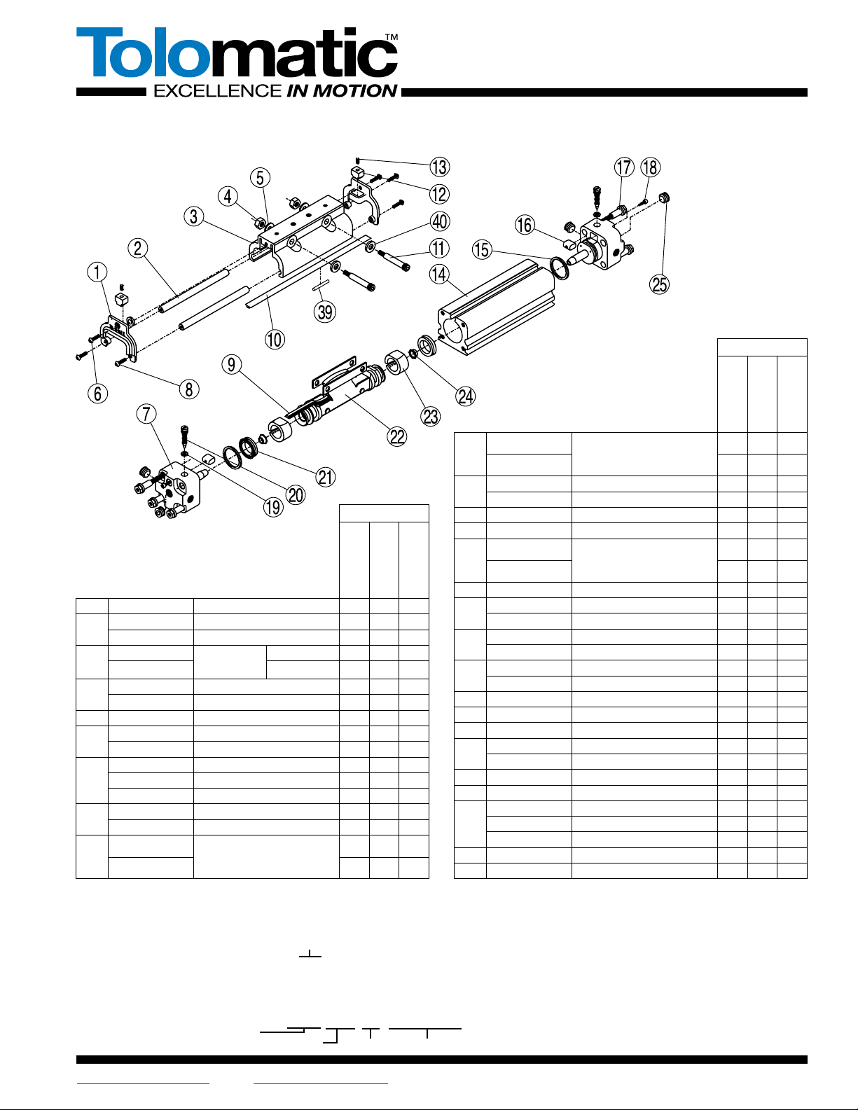
CYLINDER DISASSEMBLY INSTRUCTIONS
1. Remove Band Cylinder from machinery.
2. Loosen Screw(18).
3. Remove any foot mounting hardware if present then remove
the four Head Bolts(17) to free Cylinder Heads(7).
4. Remove the three Screws(6, 8) , Nuts(4), End Caps(1) and
Bearing Rods(2). Then remove the Shoulder Bolts(11) to free
the Carrier Bracket(3),
5. Slide Piston Bracket Assembly(22) to end of tube.
6. Remove top Dust Band(10) by lifting one end and drawing it
back across the entire length of the cylinder.
7. Remove the inner Sealing Band(9) by passing a screwdriver
or similar tool through the slot in the cylinder tube to
dislodge the band from the tube.(Take care in doing this
step to make certain that NO SCRATCHES ARE MADE in
the tube bore or slot.)
CYLINDER ASSEMBLY INSTRUCTIONS
1. CLEAN AND LUBRICATE
Thoroughly clean all components, particularly the tube bore
slot and bands. Thoroughly lubricate the tube a thin, uniform
layer of Magnalube-G®grease. Do not use SAE-grade
30-weight non-detergent oil.
2. READY INNER SEALING BAND
Lubricate rubber strip on both sides of new Sealing Band(9)
with grease. Insert Band into cylinder Tube(14) by passing it
sideways through slot in Tube. With rubber portion facing up,
center band in Tube so equal lengths of Band extend out
both ends.
CAUTION: Metal edges of Sealing Band are sharp. Exercise
caution to avoid injury to yourself or the Band and Tube when
inserting.
3. INSTALL PISTON BRACKET ASSEMBLY
Install new lubricated U-Cups(21)(seal lips facing out) and
Cushion Seals(24)(small end facing out) onto Piston-Bracket
Assembly(22). Install Wear Rings(23) on Piston with the
thinner edge and widest part of the flat inward, lining up the
wider flat portion with the band ramp and narrower flat with
the flat on the Piston. Place generous amounts of grease
around bore of Tube(14) on one end. Fill indentations on both
sides of Piston with grease and install Piston-Bracket
Assembly into Tube(14) by feeding Sealing Band(9) between
Piston and Bracket. Insert Piston into the greased end of Tube
and slide the length of the Tube to seat the Sealing Band in its
groove. Wipe excess grease from end.
NOTE: If Tube and Piston were greased properly, excess
grease should be present as Piston exits end of tube.
4. TRIM SEALING BAND
With a razor blade, remove rubber from extended band until
flush with the end of tube. With tin snips, trim band to length
indicated on table below.(Tolerance of +/- .032")
Cylinder Size Trim Length From Tube
1-1/4"(32 mm) .531"(14.86 mm)
5. INSTALL HEADS
Install new lubricated O-Rings(15) onto each Head(7). Insert
Head into Tube using a slight rocking motion until head is flush
with end of Tube. Apply Magnalube-G to threads of Head
Bolts(17) and install into head. Torque Bolts to requirements
shown below.(†When replacing the head bolts in
actuators manufactured prior to July 1, 2006, the hole for
the head bolt will need to be drilled 0.4" [10mm] deeper
to accommodate the longer screw length.) Repeat above
procedures for second head.
Cylinder Size In.-Lbs. Torque
1-1/4"(32 mm) 100-110(11.29-12.43 Nm)
6. INSTALL UPPER DUST BAND
With a razor blade, remove any rubber residue on the solid
steel surface of cleaned Dust Band(10). Place Dust Band in
slot on top of Tube(14). Remove rubber from one end of Band
flush with the end of the tube. With tin snips, trim Dust Band
to trim length requirements in Step 4. Insert trimmed Dust
Band into Head(7) positioning band above Band Clamp(16)
and tighten Screw(18). Grasp other end of Dust Band(10)
and carefully pull back out of Tube slot and back over cylinder
Head with affixed Band end. Lubricate Dust Band by filling
grooves along both sides of rubber strip with grease. Press
Dust Band back into groove in Tube.
7. INSTALL CARRIER
Position Carrier(3) on Piston-Bracket Assembly(22). Install
Shoulder Bolts(11), Washers(5) and Nuts(4) with screw
heads on port side of cylinder. Install Bearing Rods(2) in
Carrier and place End Caps(1) on Tube. Install Band
Insert(12) into pocket on End Cap(curved portion towards
carrier). Insert Spring(13) into hole of Band Insert(12).
Compress Spring and slide End Cap up to Carrier. Fasten
with Screws(6 and 8). Repeat for other end.
8. REMOVE SLACK AND AFFIX FREE END OF BAND
Work slack from Bands by moving the Carrier from the Head
with Bands secured to the opposite Head. Remove excess
rubber from free end keeping it flush with end of Tube. Cut to
trim length as before. Secure free end of Band by inserting
Band above Band Clamp(16) and tighten Screw(18).
9. CHECK ASSEMBLY
Run the Carrier Bracket(3) back and forth along the full
stroke to make certain that the cylinder is properly assem-
bled before applying air.
10. REMOUNT
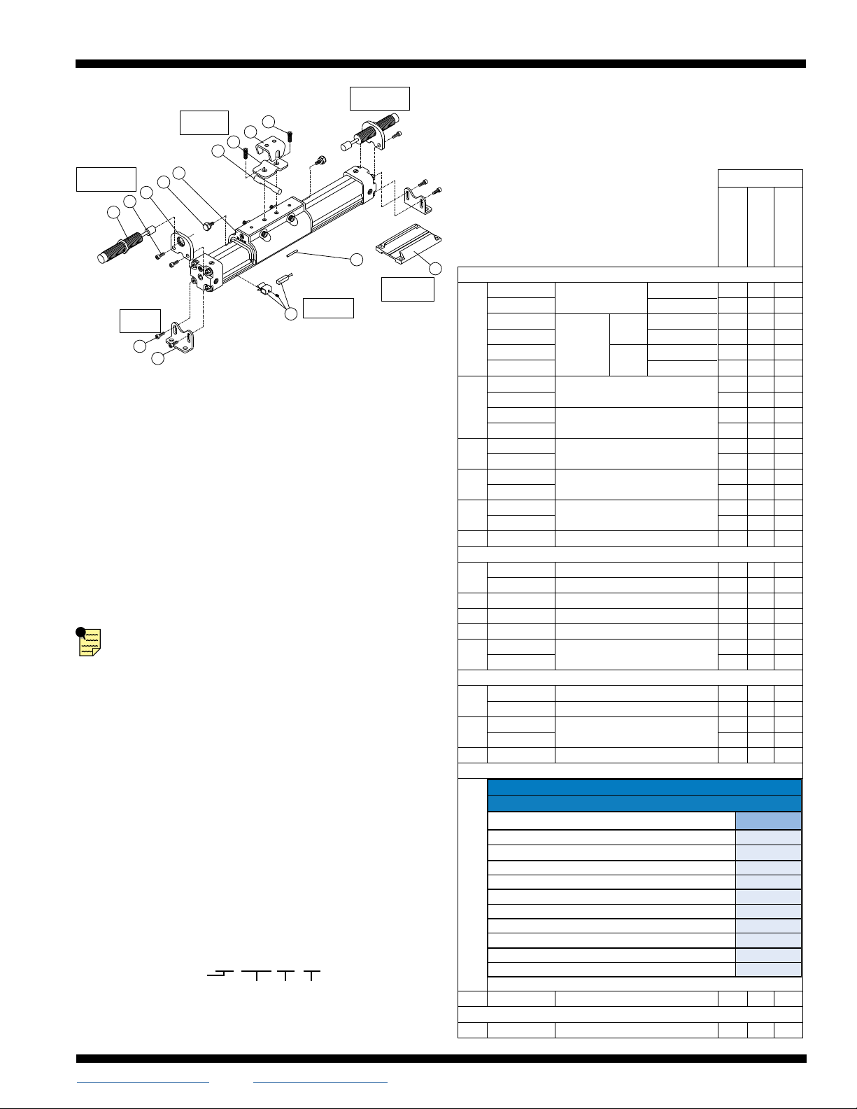
OPTIONAL ACCESSORY ASSEMBLY INSTRUCTIONS
1. SHOCK ABSORBERS
On assembled cylinder, screw Impact Bolts(29) into top of
carrier End Cap with Loctite #242. Secure Shock
Brackets(28) to cylinder Heads(7) with Socket Head Cap
Screws(27) and Loctite #242. Screw the Shock Absorber(26)
into the Shock Bracket(28). Adjust the Shock Absorber
nearest the carrier to bottom out the shock at its fullest stroke.
Back out the shock one full turn and tighten the Jam Nut.
Adjust the other Shock Absorber in the same manner.
2. TUBE SUPPORTS
Follow cylinder assembly instructions through steps 4. Before
installing second cylinder Head(7) in step 5., slide Tube
Support(40) onto cylinder Tube(14).
3. FOOT MOUNTS
On assembled cylinder, insert Screws(35) through holes in
Foot Mount Bracket(36) and install in holes on cylinder
Heads(7).
4. FLOATING MOUNT
Completely assemble cylinder. Place Pin(31), flat side
towards Carrier(3), and between the two center holes.
Place Floating Mount Clamp(32) over Pin(31) and secure to
the Carrier(3) with Screws(34) and Loctite® #242. Place
Floating Mount Bracket(33) over Pin(31) and hold in place
with a rubber band.
www.tolomatic.com • [email protected] • (763) 478-8000 • Toll Free: 1-800-328-2174
Parts Sheet #0510-4003_13_BC212ps BC212 Options – 3
QTY.
ITEM PART NO. DESCRIPTION
U.S. Conv.
Metric Taper Rc
Heads
Metric Parallel G
Heads
SHOCK ABSORBERS5
KIT
0512-9092 Shock Mount Kit3
(Hardware Only)
US Standard
Metric
Shock
Absorber
Kit2
Heavy
Duty
US Standard
Metric
Light
Duty
US Standard
Metric
A/R – –
4512-9092 – A/R A/R
0512-9090 A/R – –
4512-9090 – A/R A/R
0512-9091 A/R – –
4512-9091 – A/R A/R
26
0912-1067 Light Duty Shock 2 – –
4912-1067 – 2 2
0912-1068 Heavy Duty Shock 2 – –
4912-1068 – 2 2
27 2317-1014 Socket Head Cap Screw 4 – –
4915-1171 – 4 4
28 0912-1064 Shock Bracket 2 – –
4912-1064 – 2 2
29 0912-1063 Impact Bolt 2 – –
4912-1063 – 2 2
30 0512-1015 End Cap 2 2 2
FLOATING MOUNT
KIT 0512-9007 Floating Mount Kit US Standard 1 – –
4512-9007 Floating Mount Kit Metric – 1 1
31 0512-1009 Pin 1 1 1
32 0912-1031 Clamp 1 1 1
33 0912-1033 Bracket 1 1 1
34 0912-1029 Socket Head Cap Screw 2 – –
4912-1029 – 2 2
FOOT MOUNT
KIT10512-9125 Foot Mount Kit1US Standard A/R – –
4512-9125 Foot Mount Kit1Metric – A/R A/R
35 0801-1251 Socket Head Cap Screw 4 – –
5610-1045 – 4 4
36 0912-1008 Mounting Bracket 2 2 2
SWITCHES
37
CONFIG. CODE ORDERING
Mounting Hardware & FE conn. included
DESCRIPTION CODE
Switch Kit, Reed, Form C, 5m
BT
Switch Kit, Reed, Form C, Male Conn.
BM
Switch Kit, Reed, Form A, 5m
RT
Switch Kit, Reed, Form A, Male Conn.
RM
Switch Kit, Triac, 5m
CT
Switch Kit, Triac, Male Conn.
CM
Switch Kit, Hall-effect, Sinking, 5m
KT
Switch Kit, Hall-effect, Sinking, Male Conn.
KM
Switch Kit, Hall-effect, Sourcing, 5m
TT
Switch Kit, Hall-effect, Sourcing, Male Conn.
TM
NOTE: When ordered female connector & all mounting hardware is included
39 0910-1238 Switch Magnet 1 1 1
TUBE SUPPORTS4
40 4512-1010 Bracket41 1 1
Service Parts Ordering NOTES:
1Foot Mount Kit contains two foot mount brackets and
mounting hardware.
2Shock Field Retrofit Kit contains one Shock Absorber and
mounting hardware.
3Shock Field Mount Kit contains one set of mounting
hardware only.
4A minimum of 2 (two) Tube Supports required per cylinder.
5Standard end-of-stroke shock absorbers are designed to
operate without the assistance of the standard band cylinder
cushion. To ensure proper shock absorber performance,
make sure the air cushion is disabled.
A/R = As Required
36
26
27 28
29 30
31 32
33
34
40
39
37
35
BC2
OPTIONS
SHOCK
ABSORBERS
SHOCK
ABSORBERS
FLOATING
MOUNT
TUBE
SUPPORTS
FOOT
MOUNT
SWITCHES
5. SWITCHES
On assembled cylinder, Secure Switch to open port side of cylinder with
a Clamp and Screw. Cycle the carrier over the Switch by hand to ensure
that the carrier does not hit the switch.
NOTE: Form A Reed Switches should not be used in TTL logic
circuits. A voltage drop caused by the L.E.D. indicator will result.
For applications where TTL circuits are used, please contact
the factory.
WARNING: An ohmmeter is recommended for testing Reed Switches.
NEVER use an incandescent light bulb as a high current rush may
damage the switch.
Reed and TRIAC switches are only recommended for signalling position,
not directly powering solenoids. For shifting a solenoid, a relay or resistor
is recommended between it and the Reed Switch. Switch ratings must
not be exceeded at any time.
To Order Retrofit Kits
All Switch Kits come with 1 switch and mounting hardware.
Model
Switch Kit
Size Switch Type Code
SW ___ __ __
SW BC2 12 RT
Retrofit ordering method:
EXAMPLE:
All brand and product names are trademarks or registered trademarks of their
respective owners. Information in this document is believed accurate at time of print-
ing. However, Tolomatic assumes no responsibility for its use or for any errors that
may appear in this document. Tolomatic reserves the right to change the design or
operation of the equipment described herein and any associated motion products
without notice. Information in this document is subject to change without notice.
Visit www.tolomatic.com for the most up-to-date technical information
3800 County Road 116, Hamel, MN 55340 USA
http://www.Tolomatic.com • Email: Help@Tolomatic.com
Phone: (763) 478-8000 • Fax: (763) 478-8080 • Toll Free: 1-800-328-2174
© 2022 Tolomatic 202202281124
Parts Sheet #0510-4003_13_BC212ps BC212 Switches– 4
MAINTENANCE
The Band Cylinder
®
should be kept as clean as possible around the bands
and Carrier Bracket.
LUBRICATION
All Tolomatic Band Cylinders are prelubricated at the factory. To ensure
maximum cylinder life, the following guidelines should
be followed.
1. Filtration– We recommend the use of dry, filtered air in our
products. ‘Filtered air’ means a level of 10 Micron or less. ‘Dry’
means air should be free of appreciable amounts of moisture.
Regular maintenance of installed filters will generally keep excess
moisture in check.
2. External Lubricators (optional)– The factory prelubrication of
Tolomatic Band Cylinders will provide optimal performance
without the use of external lubrication. However, external
lubricators can further extend service life of pneumatic actuators if
the supply is kept constant.
Oil lubricators, (mist or drop) should supply a minimum of 1 drop per
20 standard cubic feet per minute to the cylinder. As a rule of thumb,
double that rate if water in the system is suspected. Demanding
conditions may require more lubricant.
If lubricators are used, we recommend a non-detergent, 20cP @
140˚F 10-weight lubricant. Optimum conditions for standard
cylinder operation is +32˚ to +125˚F (+0˚ to 51.6˚C).
NOTE: Use of external lubricators will wash away the factory
installed lubrication. External lubricants must be maintained in a
constant supply or the results will be a dry actuator prone to failure.
3. Sanitary environments– Oil mist lubricators must dispense ‘Food
Grade’ lubricants to the air supply. Use fluids with ORAL LD50
toxicity ratings of 35 or higher such as Multitherm® PG-1 or
equivalent. Demanding conditions can require a review of the
application.
CARRIER BRACKET ADJUSTMENT
The tracking tension on the Carrier Bracket may be adjusted by tightening
or loosening the two shoulder bolts and nuts on the bracket. To tighten or
loosen the bolts on the BC212 Band Cylinder® models, use an open-end
wrench and Allen wrench. Tighten the nut on the shoulder bolt until there
is no lateral movement of the bolt. Then, equally tighten each nut on the
shoulder bolts while moving the carrier by hand along the length of the
stroke. When all lateral play in the carrier is eliminated and free movement
along the length of the stroke is maintained, the carrier bracket is adjusted
properly.
CAUTION
:Make certain not to overtighten the Carrier Bracket
adjustment screws. It is possible to tighten them enough to keep the
Carrier and Piston from moving. Tightening the Carrier Bracket directly
affects the cylinder’s breakaway. The tighter the adjustment the higher
the breakaway.
CUSHION NEEDLE ADJUSTMENT
Adjust the cushion needles in the cylinder heads carefully to obtain
a smooth, hesitation free deceleration for your particular application.
If there are questions on proper adjustment, please consult
Tolomatic, Inc.
Some actuators may require
switch mounting on a specific
side of the assembly. Call
Tolomatic for details.
REPLACEMENT OF QD SWITCHES
MANUFACTURED BEFORE JULY 1, 1997:
It will be necessary to replace or
rewire the female end coupler.
Female Connector 5M

This manual suits for next models

1

Other Tolomatic Industrial Equipment manuals

Tolomatic TC07SS Use and care manual

Tolomatic

Tolomatic TC07SS Use and care manual

Tolomatic Band Cylinder BC2 Series User manual

Tolomatic

Tolomatic Band Cylinder BC2 Series User manual

Tolomatic BC4 Series User manual

Tolomatic

Tolomatic BC4 Series User manual

Tolomatic MXP50N User manual

Tolomatic

Tolomatic MXP50N User manual

Tolomatic MXP25PTP User manual

Tolomatic

Tolomatic MXP25PTP User manual

Tolomatic MXP63PTP User manual

Tolomatic

Tolomatic MXP63PTP User manual

Tolomatic BC3 Series User manual

Tolomatic

Tolomatic BC3 Series User manual

Tolomatic MXP32N Series Use and care manual

Tolomatic

Tolomatic MXP32N Series Use and care manual

Tolomatic TC15 User manual

Tolomatic

Tolomatic TC15 User manual

Tolomatic PB208 User manual

Tolomatic

Tolomatic PB208 User manual

Tolomatic MXP16N User manual

Tolomatic

Tolomatic MXP16N User manual

Tolomatic LS10 User manual

Tolomatic

Tolomatic LS10 User manual

Popular Industrial Equipment manuals by other brands

Sumitomo Z2C Guide to Operation

Sumitomo

Sumitomo Z2C Guide to Operation

Grizzly G0877 owner's manual

Grizzly

Grizzly G0877 owner's manual

GE GEH-2906B instructions

GE

GE GEH-2906B instructions

Wintriss SmartPAC PRO user manual

Wintriss

Wintriss SmartPAC PRO user manual

Emerson Rosemount 2410 instructions

Emerson

Emerson Rosemount 2410 instructions

SEW-Eurodrive BS.F Series Assembly and operating instructions

SEW-Eurodrive

SEW-Eurodrive BS.F Series Assembly and operating instructions

WALTERSCHEID K90TF Repair instructions

WALTERSCHEID

WALTERSCHEID K90TF Repair instructions

Haas HSF-325 user guide

Haas

Haas HSF-325 user guide

Dodge SLEEVOIL RXT instruction manual

Dodge

Dodge SLEEVOIL RXT instruction manual

Innova XTIRPA IN-8020 Instruction and safety manual

Innova

Innova XTIRPA IN-8020 Instruction and safety manual

Magnaflux A-2000 Series Operation manual

Magnaflux

Magnaflux A-2000 Series Operation manual

SycoTec 6045 DC-C5-80-10 operating manual

SycoTec

SycoTec 6045 DC-C5-80-10 operating manual

Wiedenmann Terra Clean 160 operating instructions

Wiedenmann

Wiedenmann Terra Clean 160 operating instructions

PI L-406 Series user manual

PI

PI L-406 Series user manual

AuCom MVS Series Product guide

AuCom

AuCom MVS Series Product guide

SCHUNK WSG 50 Assembly and operating manual

SCHUNK

SCHUNK WSG 50 Assembly and operating manual

MSW MSW-SRM-32 user manual

MSW

MSW MSW-SRM-32 user manual

Siemens SIMATIC ET 200SP HA Equipment manual

Siemens

Siemens SIMATIC ET 200SP HA Equipment manual

manuals.online logo
manuals.online logoBrands
  • About & Mission
  • Contact us
  • Privacy Policy
  • Terms and Conditions

Copyright 2025 Manuals.Online. All Rights Reserved.