Parts Sheet #0600-4002_10 LS10, LSMM10 Disassembly and Assembly Instructions – 3
TOLOMA
TIC
•
URL:
http://www
.tolomatic.com
•
Email:
[email protected] •
Fax:
(763)
478-8080
•
T
oll
Free:
1-800-328-2174
REED SWITCHES
NOTE: Form A Reed Switches should not be used in TTL logic circuits.
A voltage drop caused by the L.E.D. indicator will result. For applications
where TTL circuits are used, please contact the factory.
WARNING: An ohmmeter is recommended for testing Reed Switches.
NEVER use an incandescent light bulb as a high current rush may
damage the switch.
Reed and TRIAC switches are only recommended for signalling position,
not directly powering soleniods. For shifting a solenoid, a relay or
resistor is recommended between it and the Reed Switch. Switch
ratings must not be exceeded at any time.
NOTE: The side of the switch with the groove indicates the sensing
surface. This must face toward the magnet.
NOTE: For Hall Effect Switch Magnet, be sure the S pole of the magnet
(indicated with black dot) is facing toward the switch (down).
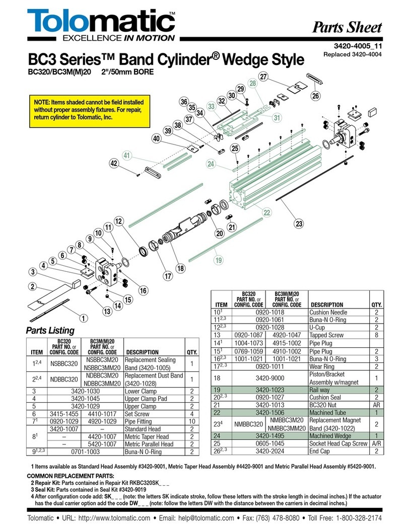
clear underside of Carrier (#6). Use Screws (#1) to hold End
Cap (#2) in place.
13. Place Band Wedges (#11) between Bands (#12,#13) at both
ends of cylinder.
14. Install new O-Rings (#23,#24) on Head Assemblies (#8) and install
Head Assemblies to cylinder. If using Square Nuts (#16) be sure
they are installed in Tube/Base before Heads are installed.
15. Install Screws (#25) and tighten Head Assemblies in place.
16. Push Carrier (#6) to one end and tighten Set Screw in Head
Assembly on that end. Push Carrier (#6) to the other end of the
Slide Cylinder to take out any slack in Bands (#12,#13) and tighten
Set Screw (#26) in Head Assemblies (#8).
17. Run Carrier (#6) back and forth along the full stroke to make
certain the Slide is properly assembled.
18. Remount the completed Slide Cylinder.
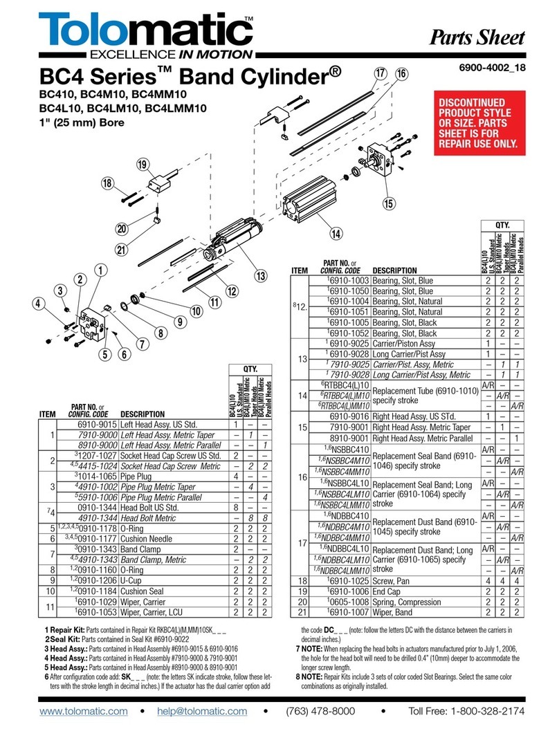
SHAFT AND BEARING REPLACEMENT
INSTRUCTIONS
Note: Shaft alignment is critical to assure proper function of the slide
cylinder.
1. Remove Slide Cylinder from machinery.
2. Loosen two Set Screws (#26) in Head Assembly (#8) on one end of
Cylinder.
3. Remove four screws (#25), and Head Assembly (#8) from same end
of Cylinder.
4. Remove Screws (#21) from one shaft (#22).
5. Slide Shaft (#22) out of Carrier (#6).
6. Remove and replace Set Screws (#5) and Bearing (#14) from open
side of Carrier (#6). Use Loctite #242 on Set Screws (#5) and screw
them into Carrier (#6) until they bottom out on bearings (#14), then
back them out one half turn.
7. Slide new Shaft (#22) through Bearings (#14). Replace Screws (#21)
loosely, use Loctite #242 on Screws (#21).
8. Hold Top Dust Band (#13) at open end of Cylinder and slide Carrier
(#6) to opposing end.
9. Tighten Screws (#21) below Carrier (#6) to 40 inch-pounds
minimum.
10. To align Shaft (#22) properly, slide carrier over next Screw (#21)
and tighten to 15 inch-pounds minimum. Repeat this until all
Screws (#21) are tight.
11. Repeat steps 5 through 11 for second Shaft (#22).
12. Place Band Wedge (#11) between Bands (#12,#13) at open end of
Cylinder.
13. Be sure O-rings are on Head Assembly (#8) and install Head
Assembly (#8) to Cylinder. If using Square Nuts (#16) be sure they
are installed in Tube/Base (#17) before Head is installed.
14. Install four Screws (#25) and tighten to 70-80 inch-pounds.
15. Position Carrier (#6) to the end of Cylinder with non-removed Head
Assembly (#8). Push Carrier (#6) back to other end to remove any
slack from Bands (#12,#13) and tighten Set Screws in Head
Assembly (#8).
16. Run Carrier back and forth along the full stroke to make certain the
Slide is properly assembled before applying air.
17. Remount the completed Slide Cylinder.
Loctite® is a registered trademark of the Loctite Corporation, www.loctite.com
Magnalube®-G is a registered trademark of the Carleton-Stuart Corporation, www.magnalube-g.com
Viton® is a registered trademark of the E.I. Du Pont de Newmours Co., www.dupont.com.
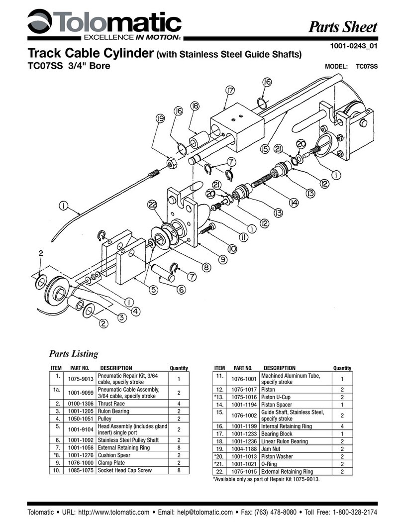
Description QTY
RT
Switch, Reed, Form A, 5M Wire
AR
RM
Switch, Reed, Form A, Male Connect
AR
BT
Switch, Reed, Form C, 5M Wire AR
BM
Switch, Reed, Form C, Male Connect AR
CT
Switch, Triac, 5M Wire AR
CM
Switch, Triac, Male Connect AR
TT
Switch, Hall, Sourcing, 5M AR
TM
Switch, Hall, Sourcing, Male Connect AR
KT
Switch, Hall, Sinking, 5M AR
KM
Switch, Hall, Sinking, Male Connect AR
0610-9100 Rail and Rail Hardware (specify stroke) AR
SWITCH AND HARDWARE LISTING
OPTIONAL ACCESSORIES
Shock Absorber (Shock absorbers are sold individually.)
DESCRIPTION PART NO.
1"/25mm Light Duty 0610-9022
1"/25mm Heavy Duty 0610-9023
Inductive DC Proximity Sensors (also sold individually.)
DESCRIPTION PART NO.
DC 10-24 NPN NO Sink 0610-1023
DC 10-24 PNP NO Source 0610-1024
NOTE: NO=Normally Open
Note: Linear Slide is shown with Optional
Shock Absorbers.
.93"
1.05"
TOLOMATIC
TOLOMATIC
.08"
.37"
1.31"
SENSING SURFACE
SENSING SURFACE
PART NO. or
CONFIG. CODE
ITEM


