Tolomatic Band Cylinder BC2 Series User manual

Tolomatic • URL: http://www.tolomatic.com • Email: [email protected] • Fax: (763) 478-8080 • Toll Free: 1-800-328-2174
Parts Sheet
0510-4004_10_BC215ps
BC2 Series™Band Cylinder®
BC215, BC2M15, BC2MM15
1-1/2” (40 mm) Bore
19 20
21
22
23
24
25
18
16
13 17
12
15
14
11
10
39
9
8
7
6
2
3
4
5
1
QTY.
ITEM
PART NO. or
CONFIG. CODE
DESCRIPTION
BC215
U.S. Standard
BC2M15 Metric
Taper Rc Heads
BC2M15 Metric
Parallel G Heads
134515-1002 End Cap 2 2 2
230915-1170 Bearing Rod 2 – –
4915-1170 – 2 2
3 0515-1003 Carrier, with
magnet assy.
US Standard
Metric
1 – –
4515-1003 – 1 1
4 0912-1016 Nut 2 – –
4912-1016 – 2 2
5 1004-1144 Washer 2 2 2
6 0910-1081 Socket Head Cap Screw 2 – –
4912-1005 – 2 2
7
0515-9021
Head Assembly
2 – –
4515-9021 – 2 –
5515-9021 – – 2
8 0915-1172 Socket Head Cap Screw 4 – –
4915-1172 – 4 4
93,4
NSBBC215 Replacement Seal Band
specify stroke
A/R – –
NSBBC2M15 – A/R –
NSBBC2MM15 – – A/R
103,4
NDBBC215 Replacement Dust Band
specify stroke
A/R – –
NDBBC2M15 – A/R –
NDBBC2MM15 – – A/R
QTY.
ITEM
PART NO. or
CONFIG. CODE
DESCRIPTION
BC215
U.S. Standard
BC2M15 Metric
Taper Rc Heads
BC2M15 Metric
Parallel G Heads
11 0915-1089 Shoulder Bolt 2 – –
4915-1089 – 2 2
1234515-1012 Band Insert 2 2 2
1330515-1000 Spring 2 2 2
144
RTBBC215 Replacement Tube
specify stroke
A/R – –
RTBBC2M15 – A/R –
RTBBC2MM15 – – A/R
1530915-1178 O-Ring 2 2 2
1610910-1343 Band Clamp 2 – –
4910-1343 – 2 2
1720512-1011 Head Bolt 8 – –
4512-1011 – 8 8
1811301-1172 Socket Head Cap Screw 2 – –
4915-1005 – 2 2
1910910-1178 O-Ring 2 2 2
2010915-1177 Cushion Needle 2 2 2
2130915-1042 U-Cup 2 2 2
22 0915-9013 Piston Bracket Assembly 1 – –
4915-9013 – 1 1
2330915-1110 Wear Ring 2 2 2
2430915-1184 Cushion Seal 2 2 2
251
1004-1073
Pipe Plug
4 – –
4915-1002 – 4 –
5915-1006 – – 4
39 0910-1238 Switch Magnet 1 1 1
1 Items available in Standard Head Assembly #0515-9021
and Metric Taper Head Assembly #4415-9021
and Metric Parallel Head Assembly #5515-9021
2 When replacing the head bolts in actuators manufactured prior to July
1, 2006, the hole for the head bolt will need to be drilled 0.4” (10mm)
deeper to accommodate the longer screw length.
COMMON REPLACEMENT PARTS:
3 Repair Kit: Parts contained in Repair Kit RKBC2(M,MM)15SK_ _ _
4 After configuration code add: SK_ _ _ (note: the letters SK indicate
stroke, follow these letters with the stroke length in decimal inches.) If
the actuator has the dual carrier option add the code DC_ _ _ (note:
follow the letters DC with the distance between the carriers in
decimal inches.)
List of Parts

Tolomatic • URL: http://www.tolomatic.com • Email: [email protected] • Fax: (763) 478-8080 • Toll Free: 1-800-328-2174
2 – Instructions BC215, BC2M15, BC2MM15 Parts Sheet #0510-4004_10_BC215ps
CYLINDER DISASSEMBLY INSTRUCTIONS
1. Remove Band Cylinder from machinery.
2. Loosen Screw (18).
3. Remove any Foot mounting hardware if present then remove the
four Head Bolts (17) to free Cylinder Heads (7).
4. Remove the three Screws (6, 8), Nuts (4), End Caps (1) and
Bearing Rods (2). Then remove Shoulder Bolts (11) to free the
Carrier Bracket (3),
5. Slide Piston Bracket Assembly (22) out end of tube.
6. Remove top Dust Band (10) by lifting one end and drawing it
back across the entire length of the cylinder.
7. Remove the inner Sealing Band (9) by passing a screwdriver or
similar tool through the slot in the cylinder tube to dislodge the
band from the tube. (Take care in doing this step to make certain
that NO SCRATCHES ARE MADE in the tube bore or slot.)
CYLINDER ASSEMBLY INSTRUCTIONS
1. CLEAN AND LUBRICATE
Thoroughly clean all components, particularly the tube bore slot
and bands. Thoroughly lubricate the tube and all rubber parts
with Magnalube
®
-G grease. Do not use SAE-grade 30-weight
non-detergent oil.
2. READY INNER SEALING BAND
Lubricate rubber strip on both sides of new Sealing Band (9) with
Magnalube-G
®
grease. Insert Band into cylinder Tube (14) by
passing it sideways through slot in tube. With rubber portion facing
up, center band in Tube so equal lengths of Band extend out
both ends.
CAUTION: Metal edges of Sealing Band are sharp. Exercise
caution to avoid injury to yourself or the Band and Tube
when inserting.
3. INSTALL PISTON BRACKET ASSEMBLY
Install new lubricated U-Cups (21) (seal lips facing out) and
Cushion Seals (24) (small end facing out) onto Piston-Bracket
Assembly (22). Install the Wear Rings (23) on the Piston with the
thinner edge and widest part of the flat inward, lining up the
wider flat portion with the band ramp and narrower flat portion
with the flat on the Piston. Place generous amounts of grease
around bore of Tube (14) on one end. Fill indentations on both
sides of Piston with grease and install Piston-Bracket Assembly
into Tube (14) by feeding Sealing Band (9) between Piston and
Bracket. Insert Piston into the greased end of Tube and slide the
length of the Tube to seat the Sealing Band in its groove. Wipe
excess grease from end.
NOTE: If Tube and Piston were greased properly, excess grease
should be present as Piston exits end of tube.
4. TRIM SEALING BAND
With a razor blade, remove rubber from extended band until
flush with the end of tube. With tin snips, trim band to length
indicated on table below. (Tolerance of +/- .032")
Cylinder Size Trim Length From Tube
1-1/2" (40 mm) .656" (16.51 mm)
5. INSTALL HEADS
Install new lubricated O-Rings (19) onto Head (7). Insert Head into
Tube using a slight rocking motion until head is flush with end of
Tube. DO NOT TWIST – twisting the Head when installing can
result in a cut O-ring. Apply Magnalube
®
-G to threads of Head
Bolts (17) and install into head. Torque Bolts to requirements
shown below. (†When replacing the head bolts in actuators
manufactured prior to July 1, 2006, the hole for the head bolt will
need to be drilled 0.4" [10mm] deeper to accommodate the longer
screw length.) Repeat above procedures for second head.
Cylinder Size In.-Lbs. Torque
1-1/2" (40 mm) 100-110 (11.29-12.43 Nm)
6. INSTALL UPPER DUST BAND
With a razor blade, remove any rubber residue on the solid steel
surface of cleaned Dust Band (10). Place Dust Band in slot on
top of Tube (14). Remove rubber from one end of Band flush with
the end of the tube. With tin snips, trim Dust Band to trim length
requirements in Step 4. Insert trimmed Dust Band into Head (7)
positioning band above Band Clamp (16) and tighten Screw (18).
Grasp other end of Dust Band (10) and carefully pull back out of
Tube slot and back over cylinder Head with affixed Band end.
Lubricate Dust Band by filling grooves along both sides of rubber
strip with grease. Press Dust Band back into groove in Tube.
7. INSTALL CARRIER
Position Carrier (3) on Piston-Bracket Assembly (22). Loosely
install Shoulder Bolts (11), Washers (5) and Nuts (4) with screw
heads on port side of cylinder. Install Bearing Rods (2) in Carrier
and place End Caps (1) on Tube. Install Band Insert (12) into
pocket on End Cap (curved portion towards carrier). Insert
Spring (13) into hole of Band Insert (12). Compress Spring and
slide End Cap up to Carrier. Fasten with Screws (6 and 8).
Repeat for other end. Tighten carrier Shoulder Bolts (11) and
Nuts (4).
8. REMOVE SLACK AND AFFIX FREE END OF BAND
Work slack from Bands by moving the Carrier from the Head with
Bands secured to the opposite Head. Remove excess rubber
from free end keeping it flush with end of Tube. Cut to trim length
as before. Secure free end of Band by inserting Band above
Band Clamp (16) and tighten Screw (18).
9. CHECK ASSEMBLY
Run the Carrier Bracket (3) back and forth along the full stroke to
make certain that the cylinder is properly assembled before
applying air.
10. REMOUNT
OPTIONAL ACCESSORY ASSEMBLY INSTRUCTIONS
1. SHOCK ABSORBERS
On assembled cylinder, screw Impact Bolts (29) into top of
carrier End Cap with Loctite #242. Secure Shock Brackets (28) to
cylinder Heads (7) with Socket Head Cap Screws (27) and Loctite
#242. Screw the Shock Absorber (26) into the Shock Bracket (28).
Adjust the Shock Absorber nearest the carrier to bottom out the
shock at its fullest stroke. Back out the shock one full turn and
tighten the Jam Nut. Adjust the other Shock Absorber in the
same manner.
2. TUBE SUPPORTS
Follow cylinder assembly instructions through steps 4. Before
installing second cylinder Head (7) in step 5., slide Tube
Support (48) onto cylinder Tube (14).
3. FOOT MOUNTS
On assembled cylinder, insert Screws (36) through holes in Foot
Mount Bracket (35) and install in holes on cylinder Heads (7).
4. FLOATING MOUNT
Completely assemble cylinder. Place Pin (31), flat side towards
Carrier (3), and between the two center holes. Place Floating
Mount Clamp (32) over Pin (31) and secure to the Carrier (3) with
Screws (34) and Loctite
®
#242. Place Floating Mount Bracket (33)
over Pin (31) and hold in place with a rubber band.

Tolomatic • URL: http://www.tolomatic.com • Email: [email protected] • Fax: (763) 478-8080 • Toll Free: 1-800-328-2174
Parts Sheet #0510-4004_10_BC215ps
BC215, BC2M15, BC2MM15 Options – 3
Parts Sheet #0510-4004_10_BC215ps
QTY.
ITEM
PART NO.
DESCRIPTION
BC215
U.S. Standard
BC2M15 Metric
Taper Rc Heads
BC2M15 Metric
Parallel G Heads
SHOCK ABSORBERS5
KIT
0515-9092 Shock Mount Kit3
(Hardware Only)
US Standard
Metric
Shock
Absorber
Kit2
Heavy
Duty
US Standard
Metric
Light
Duty
US Standard
Metric
A/R – –
4515-9092 – A/R A/R
0515-9090 A/R – –
4515-9090 – A/R A/R
0515-9091 A/R – –
4515-9091 – A/R A/R
26
0912-1067 Light Duty Shock 2 – –
4912-1067 – 2 2
0912-1068 Heavy Duty Shock 2 – –
4912-1068 – 2 2
27 2317-1014 Socket Head Cap Screw 4 – –
4915-1171 – 4 4
28 0915-1096 Shock Bracket 2 – –
4915-1096 – 2 2
29 0915-1095 Impact Bolt 2 – –
4915-1095 – 2 2
30 0515-1015 End Cap 2 2 2
FLOATING MOUNT
KIT 0515-9007 Floating Mount Kit US Standard 1 – –
4515-9007 Floating Mount Kit Metric – 1 1
31 0515-1009 Pin 1 1 1
32 0912-1031 Clamp 1 – –
4915-1193 – 1 1
33 0915-9018 Bracket 1 1 1
34 0910-1199 Socket Head Cap Screw 2 – –
4912-1029 – 2 2
FOOT MOUNT
KIT10515-9125 Foot Mount Kit1US Standard A/R – –
4515-9125 Foot Mount Kit1Metric – A/R A/R
35 0915-1150 Mounting Bracket 2 2 2
36 1004-1066 Socket Head Cap Screw 4 – –
4915-1003 – 4 4
SWITCHES
37
CONFIG. CODE ORDERING
Mounting Hardware & FE conn. included
DESCRIPTION CODE
Switch Kit, Reed, Form C, 5m
BT
Switch Kit, Reed, Form C, Male Conn.
BM
Switch Kit, Reed, Form A, 5m
RT
Switch Kit, Reed, Form A, Male Conn.
RM
Switch Kit, Triac, 5m
CT
Switch Kit, Triac, Male Conn.
CM
Switch Kit, Hall-effect, Sinking, 5m
KT
Switch Kit, Hall-effect, Sinking, Male Conn.
KM
Switch Kit, Hall-effect, Sourcing, 5m
TT
Switch Kit, Hall-effect, Sourcing, Male Conn.
TM
NOTE: When ordered female connector & all mounting hardware is included
39 0910-1238 Switch Magnet 1 1 1
TUBE SUPPORTS4
40 4515-1010 Bracket41 1 1
Service Parts Ordering NOTES:
1
Foot Mount Kit contains two foot mount brackets and
mounting hardware.
2
Shock Field Retrofit Kit contains one Shock Absorber and
mounting hardware.
3
Shock Field Mount Kit contains one set of mounting
hardware only.
4
A minimum of 2 (two) Tube Supports required per cylinder.
5
Standard end-of-stroke shock absorbers are designed to
operate without the assistance of the standard band cylinder
cushion. To ensure proper shock absorber performance, make
sure the air cushion is disabled.
A/R = As Required
Switch Ordering NOTES:
To order field retrofit switch and hardware kits for all Tolo-
matic actuators: SW (Then the model and bore size, and type
of switch required)
Example: SWBC215RT
(Hardware and Form A Reed switch with 5 meter lead for 1.5"
bore BC2 band cylinder)
5. SWITCHES
On assembled cylinder, Secure Switch to open port side of cylinder
with a Clamp and Screw. Cycle the carrier over the Switch by hand
to ensure that the carrier does not hit the switch.
NOTE: Form A Reed Switches should not be used in TTL logic
circuits. A voltage drop caused by the L.E.D. indicator will result.
For applications where TTL circuits are used, please contact
the factory.
WARNING: An ohmmeter is recommended for testing Reed
Switches. NEVER use an incandescent light bulb as a high current
rush may damage the switch.
Reed and TRIAC switches are only recommended for signalling
position, not directly powering solenoids. For shifting a solenoid, a
relay or resistor is recommended between it and the Reed Switch.
Switch ratings must not be exceeded at any time.
List of Parts
BC2
OPTIONS
36
26
27 28
29 30
31 32
33
34
40
39
37
35
SHOCK
ABSORBERS
SHOCK
ABSORBERS
FLOATING
MOUNT
TUBE
SUPPORTS
FOOT
MOUNT
SWITCHES
3800 County Road 116, Hamel, MN 55340
http://www.Tolomatic.com • Email: Help@Tolomatic.com
Phone: (763) 478-8000 • Fax: (763) 478-8080 • Toll Free: 1-800-328-2174
8
© 2017 Tolomatic 201708161449
Information furnished is believed to be accurate
and reliable. However, Tolomatic assumes no
responsibility for its use or for any errors that may
appear in this document. Tolomatic reserves the
right to change the design or operation of the
equipment described herein and any associated
motion products without notice. Information in
this document is subject to change without notice.
4 – Switches / Maintenance BC215, BC2M15, BC2MM15 Parts Sheet #0510-4004_10_BC215ps
MAINTENANCE
The Band Cylinder
®
should be kept as clean as possible around the
bands and Carrier Bracket.
LUBRICATION
All Tolomatic Band Cylinders are pre-lubricated at the factory. To
ensure maximum cylinder life, the following guidelines should
be followed.
1. Filtration– We recommend the use of dry, filtered air in our
products. ‘Filtered air’ means a level of 10 Micron or less. ‘Dry’
means air should be free of appreciable amounts of moisture.
Regular maintenance of installed filters will generally keep
excess moisture in check.
2. External Lubricators (optional)– The factory pre-lubrication of
Tolomatic Band Cylinders will provide optimal performance
without the use of external lubrication. However, external
lubricators can further extend service life of pneumatic
actuators if the supply is kept constant.
Oil lubricators, (mist or drop) should supply a minimum of 1
drop per 20 standard cubic feet per minute to the cylinder. As a
rule of thumb, double that rate if water in the system is
suspected. Demanding conditions may require more lubricant.
If lubricators are used, we recommend a non-detergent, 20cP
@ 140˚F 10-weight lubricant. Optimum conditions for standard
cylinder operation is +32˚ to +125˚F (+0˚ to 51.6˚C).
NOTE: Use of external lubricators will wash away the factory
installed lubrication. External lubricants must be maintained in a
constant supply or the results will be a dry actuator prone to failure.
3. Sanitary environments– Oil mist lubricators must dispense
‘Food Grade’ lubricants to the air supply. Use fluids with ORAL
LD50 toxicity ratings of 35 or higher such as Multitherm
®
PG-1 or equivalent. Demanding conditions can require a review
of the application.
CARRIER BRACKET ADJUSTMENT
The tracking tension on the Carrier Bracket may be adjusted by
tightening or loosening the two shoulder bolts and nuts on the
bracket. To tighten or loosen the bolts on the BC215 Band Cylinder
®
models, use an open-end wrench and Allen wrench. Tighten the nut
on the shoulder bolt until there is no lateral movement of the bolt.
Then, equally tighten each nut on the shoulder bolts while moving
the carrier by hand along the length of the stroke. When all lateral
play in the carrier is eliminated and free movement along the length
of the stroke is maintained, the carrier bracket is adjusted properly.
CAUTION
: Make certain not to overtighten the Carrier Bracket
adjustment screws. It is possible to tighten them enough to keep the
Carrier and Piston from moving. Tightening the Carrier Bracket
directly affects the cylinder’s breakaway. The tighter the adjustment
the higher the breakaway.
CUSHION NEEDLE ADJUSTMENT
Adjust the cushion needles in the cylinder heads carefully to obtain
a smooth, hesitation free deceleration for your particular application.
If there are questions on proper adjustment, please consult
Tolomatic, Inc.
PERFORMANCE
THE NOTCHED
FACE OF THE
SWITCH INDICATES
THE SENSING
SURFACE AND
MUST FACE
TOWARD THE
MAGNET.
THE NOTCHED
GROOVE IN THE
ACTUATOR
INDICATES THE
GROOVE TO
INSTALL THE
SWITCH. CONTACT
TOLOMATIC IF
SWITCHES ARE
REQUIRED ON
ANOTHER SIDE OF
ACTUATOR.
0
50
100
150
200
0100 200 300 400 500
VOLTAGE A.C. or D.C.
CURRENT D.C (mA)
REED FORM A
R
E
E
D
F
O
R
M
C
TEMP. vs CURRENT, DC REED VOLTAGE DERATING, DC REEDTEMP. vs CURRENT, AC REED
0
100
200
300
400
500
600
020406080 100 120 140 160
LOAD CURRENT (mA)
OPERATING TEMPERATURE (F)
REED FORM C
REED FORM A
0
200
400
600
800
1000
020406080 100 120 140 160
LOAD CURENT (mA)
OPERATING TEMPERATURE (F)
TRIAC
RT & RM DC REED, FORM A
BT & BM DC REED, FORM C
CT & CM AC REED, TRIAC
TT & TM HALL-EFFECT, SOURCING, PNP
KT & KM HALL-EFFECT, SINKING, NPN
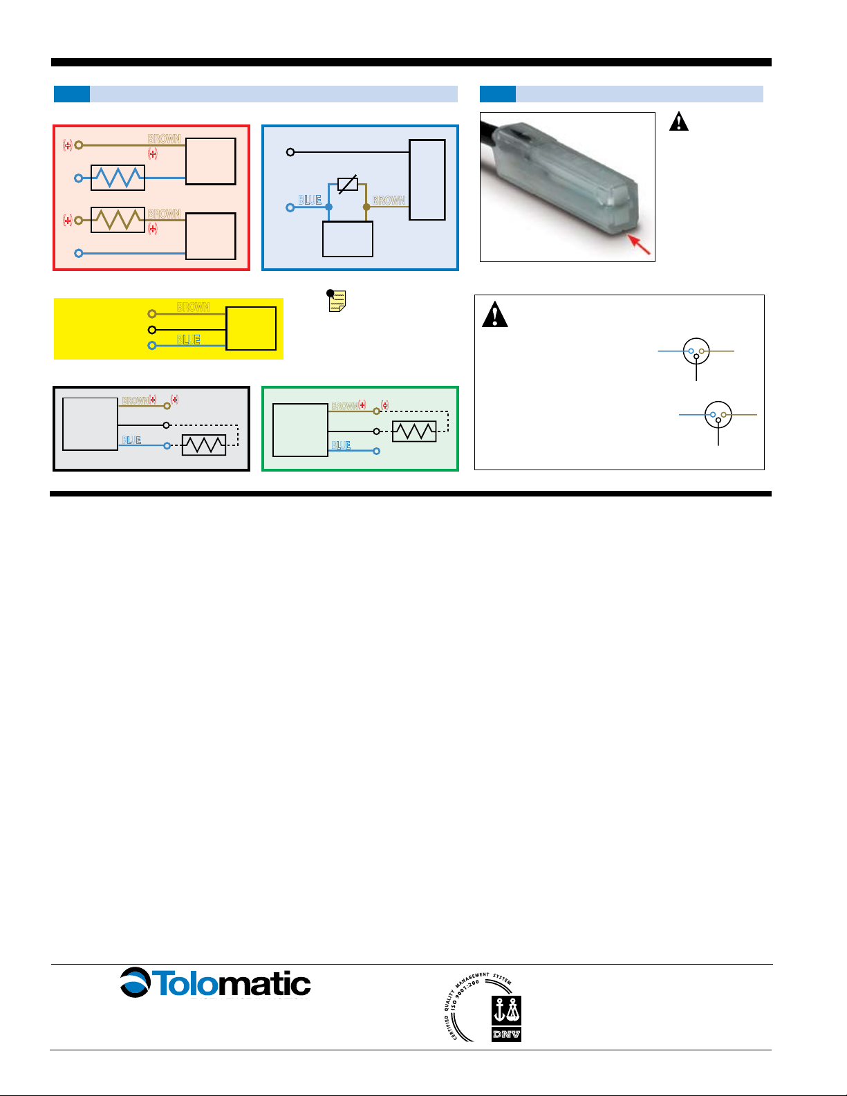
REED
SWITCH
LOAD
BROWN
BLUE
(-) (-)
(+)(+)
REED
SWITCH
LOAD
BROWN
BLUE
(-)
(-)
(+)(+)
OR
AC
COM
LOAD
INPUT
TRIAC
SWITCH
120V
ac
Max.
MOV
BROWN
BLUE
REED
SWITCH
COMMON
NORMALL
Y CLOSED
NORMALLY OPEN
BROWN
BLACK
BLUE
HALL-EFFECT
SOURCING
SWITCH
BLACK
LOAD
BROWN
BLUE (-)
(+)
(-)
(+)
HALL-EFFECT
SINKING
SWITCH
BROWN
BLACK
BLUE (-)
(+)
(-)
(+)
LOAD
WIRING DIAGRAMS INSTALLATION INFORMATION
Some actuators may
require switch mount-
ing on a specific side
of the assembly. Call
Tolomatic for details.
Female Connector 5M
SWITCHES
There are 10 sensing choices: DC reed, form A (open) or form C (open or
closed); AC reed (Triac, open); Hall-effect, sourcing, PNP (open); Hall-effect,
sinking, NPN (open); each with either flying leads or QD (quick disconnect).
Commonly used to send analog signals to PLC (programmable logic
controllers), TLL, CMOS circuit or other controller device. These switches are
activated by the actuator’s magnet.
Switches contain reverse polarity protection. QD cables are shielded; shield
should be terminated at flying lead end.
If necessary to remove factory installed switches, be sure to reinstall on the
same of side of actuator with scored face of switch toward internal magnet.
**
WARNING
: Do not exceed power rating (Watt = Voltage X Amperage). Permanent damage to sensor will occur.
*QD = Quick Disconnect; Male coupler is located 6" [152mm} from sensor,
Female coupler to flying lead distance is 197" [5m] also see Cable Shielding specification above
REPLACEMENT OF QD SWITCHES MANUFACTURED BEFORE JULY 1, 1997:
It will be necessary to replace or rewire the female end coupler.
CAUTION: DO NOT OVER TIGHTEN SWITCH HARDWARE WHEN INSTALLING!
CURRENT
Quick disconnect
Wiring
BROWN
BLACK
BLUE
+
-
SIGNAL
OLD
Quick disconnect
Wiring
BROWN
BLACK
BLUE
+
-
SIGNAL
†Shielded from the female quick disconnect coupler to the flying leads. Shield should be terminated at flying lead end.
§
Maximum current 500mA (not to exceed 10VA) Refer to Temperature vs. Current graph and Voltage Derating graph
§§
Maximum current 250mA (not to exceed 3VA) Refer to Temperature vs. Current graph and Voltage Derating graph
Reed Switch Life Expectancy: Up to
200,000,000 cycles (depending on load cur-
rent, duty cycle and environmental conditions)
DC REED, AC REED (TRIAC)
AND HALL-EFFECT
QUICK-DISCONNECT
COUPLER - MALE END
QUICK-DISCONNECT
COUPLER - FEMALE END
SPECIFICATIONS
REED DC REED AC HALL-EFFECT DC
ORDER CODE
RT RM BT BM CT CM TT TM KT KM
LEAD 5m QD* 5m QD* 5m QD* 5m QD* 5m QD*
CABLE SHIELDING Unshielded Shielded† Unshielded Shielded† Unshielded Shielded† Unshielded Shielded† Unshielded Shielded†
SWITCHING LOGIC "A" Normally Open "C" Normally Open or Closed Triac Normally Open PNP (Sourcing) Normally
Open NPN (Sinking) Normally Open
MECHANICAL CONTACTS Single-Pole Single-Throw Single-Pole Double-Throw Single-Pole Single-Throw NO, These Are Solid State Components
COIL DIRECT Yes Yes Yes —
POWER LED None None None None None
SIGNAL LED Red Red Red
OPERATING VOLTAGE 200 Vdc max. 120 Vdc max. 120 Vac max. 5 - 25 Vdc
OUTPUT RATING — — 25 Vdc, 200mA dc
OPERATING TIME 0.6 msec max.
(including bounce)
0.7 msec max.
(including bounce) —< 10 micro sec.
OPERATING TEMPERATURE -40°F [-40°C] to 158°F [70°C] 0°F [-18°C] to 150°F [66°C]
RELEASE TIME 1.0 msec. max. — —
ON TRIP POINT — — 150 Gauss maximum
OFF TRIP POINT — — 40 Gauss minimum
**POWER RATING (WATTS) 10.0
§
3.0
§ §
10.0 5.0
VOLTAGE DROP 2.6 V typical at 100 mA NA — —
RESISTANCE 0.1 Ω Initial (Max.) — —
CURRENT CONSUMPTION —1 Amp at
86°F [30°C]
0.5 Amp at
140°F [60°C] 200 mA at 25 Vdc
FREQUENCY —47 - 63 Hz —
CABLE MIN.
BEND
RADIUS
STATIC 0.630" [16mm]
DYNAMIC Not Recommended
REPLACEMENT OF QD SWITCHES
MANUFACTURED BEFORE JULY 1, 1997:
It will be
necessary to
replace or
rewire the
female end
coupler.
This manual suits for next models
3
Other Tolomatic Industrial Equipment manuals

Tolomatic
Tolomatic PB208 User manual

Tolomatic
Tolomatic MXP16N User manual

Tolomatic
Tolomatic BC4 Series User manual

Tolomatic
Tolomatic Band Cylinder BC2 Series User manual

Tolomatic
Tolomatic TC15 User manual

Tolomatic
Tolomatic LS10 User manual

Tolomatic
Tolomatic MXP50N User manual

Tolomatic
Tolomatic MXP25PTP User manual

Tolomatic
Tolomatic MXP32N Series Use and care manual

Tolomatic
Tolomatic TC07SS Use and care manual


