Tolomatic MXP63PTP User manual
Tolomatic • URL: http://www.tolomatic.com • Email: [email protected] • Fax: (763) 478-8080 • Toll Free: 1-800-328-2174
Parts Sheet
8100-4117_05_MXP63Pps
3
4
1
2
5
12
13
19
14
6
10
8
9
26
17
16
18
21
22
20
23
24
25
15
7
11
31
32
34
35
36
29
28
80
Single-end Porting Head
Return Single-end Porting Head
81
27
30b
30a
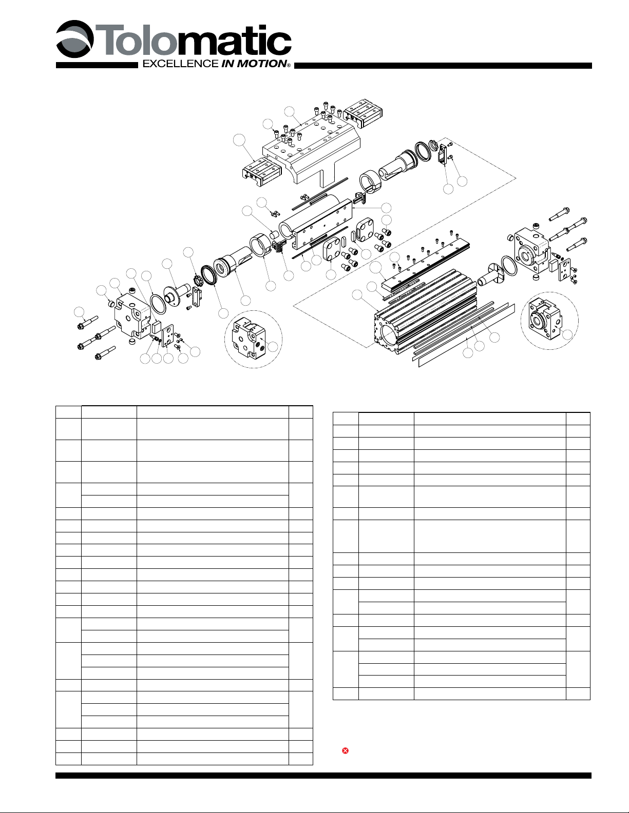
MXP63P Profiled Rail Bearing 63mm (2-1⁄2inch) Bore
List of Parts
Models:
MXP63PTP MXP63PGP MXP63PNP
MXP63PST MXP63PSG MXP63PSN
Both Metric and Inch models
ITEM
PART NO. or
CONFIG. CODE DESCRIPTION QTY.
1
RTBMXP63P
Replacement Tube (8163-1010) Specify Stroke A/R
2
NMBMXP63P
Replacement Magnet Band (8163-1019)
Specify Stroke
2A/R
1
3
NDBMXP63P
Replacement Dust Band (8163-1018)
Specify Stroke
A/R
1
4
NSBMXP63P
Replacement Seal Band (8163-1017)
Specify Stroke
A/R
5 8163-1512 Piston Bracket (inch) 1
8163-1012 Piston Bracket (metric)
16 8163-1007 Band Ramp 2
17 8163-1006 End Cap 2
18 0925-1027 U-Cup 2
19 0925-1012 Cushion Seal 2
10 8163-1004 Piston 2
11 0603-1016 Socket Head Cap Screw 4
112 8163-1059 Wiper 2
13 8163-1058 Magnet 1
14 8163-1005 Wear Ring 2
15 0925-1087 Head Screw (inch) 8
4925-1047 Head Screw (metric)
16 8163-1011 Head Assembly, NPT
28163-1046 Head Assembly, BSPT Metric Taper
8163-1047 Head Assembly, ISO Metric Parallel
217 0774-1007 O-Ring 2
218 0920-1029 Pipe Fitting Plug, 3/8 NPT
64920-1029 Pipe Fitting Plug, 3/8-19
5920-1006 Pipe Fitting Plug, G 3/8
19 4910-1004 Socket Head Cap Screw 4
220 8163-1039 Band Clamp 2
221 0915-1044 Set Screw 4
ITEM
PART NO. or
CONFIG. CODE DESCRIPTION QTY.
222 0920-1024 Flat Head Cap Screw 4
223 8163-1038 Band Wedge 2
224 0720-1003 O-Ring 2
225 8163-1065 Needle Screw 2
226 0925-1158 Cushion 2
127 8163-1028 Bearing 2
28
NNRMXP63P
Replacement Nut Rail (8163-1053)
Specify Stroke A/R
29 4415-1001 Socket Head Cap Screw A/R
430a
430b
NPRMXP63P
Replacement Bearing Rail (Specify stroke)
add DW for Dual Carrier
add BB for optional Bearing Blocks
A/R
31 8163-1034 Carrier Adjustment Plate 2
32 8163-1076 Bearing 2
33 Number is not used
34 2324-1014 Socket Head Cap Screw (inch) 8
8163-1070 Socket Head Cap Screw (metric)
35 4415-1000 Socket Head Cap Screw 12
36 8163-1521 Carrier (inch) 1
8163-1021 Carrier (metric)
380 8163-9002 Head Assy, NPT, Single-end Porting
18163-9008
Head Assy, BSPT Metric Taper, Single-end Porting
8163-9009
Head Assy, ISO Metric Parallel, Single-end Porting
381 8163-9003
Head Assembly, Return, Single-end Porting
1
1Parts included in Repair Kits RKMXP63PSK (inch), indicate stroke length in inches
RKMXP63PSM (millimeters), indicate stroke length in millimeters
2Parts included in Head Assemblies (16)
3Part is exclusive to single-end porting option
4Bearing Blocks and/or Bearing Rail purchased before Oct. 1, 2014 are NOT com-
patible with current Bearing Blocks and Bearing Rails purchased after Oct. 1, 2014.
Tolomatic • URL: http://www.tolomatic.com • Email: [email protected] • Fax: (763) 478-8080 • Toll Free: 1-800-328-2174
2 – Instructions MXP63P Parts Sheet #8100-4117_05_MXP63Pps
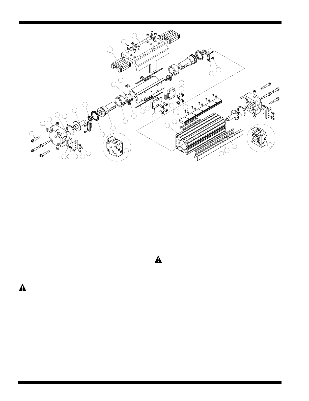
CYLINDER DISASSEMBLY INSTRUCTIONS
Begin with a clean work area. Make sure all replacement parts are avail-
able and have no visual damage or defects. The following tools and
materials are recommended for proper disassembly and assembly. (Exact
wrench sizes will vary depending on cylinder size)
• Allen wrench set (Inch and Metric)
• Small straight edge screwdriver
• Socket wrench & socket set
• Needle nose pliers
• Tin snips
• Razor Blade
• RheoGel TEK664 grease
For best actuator performance it is recommended that the following
instructions be read and followed carefully.
1. REMOVE BAND CYLINDER FROM MACHINERY
Remove all mounting hardware and air connections. If present, from the
Cylinder Heads (16) and/or Carrier (36).
2. REMOVE CARRIER FROM CYLINDER
Remove Screws (35) from Carrier (36). Slowly lift up the Carrier and
remove it from the cylinder.
CAUTION: Contaminating the Bearing Block will hinder the operation of
the cylinder. Do not remove the Bearing Blocks from the Rails. If the
Bearing Blocks need to be replaced so will the Bearing Rail.
Remove Screws (34), Adjustment Blocks (31) and Carrier Bearings (32)
from the cylinder.
3. REMOVE BEARING BLOCKS AND BEARING RAIL (OPTIONAL)
The MX Bearing System is designed to provide maximum life. Should the
Bearing Blocks need replacement, the Bearing Rail will need to be replaced
as well. Bearing Blocks (30b) and Bearing Rail (30a) must remain together.
If the cylinder stroke requires two Bearing Rails to be mounted, the cylinder
will need to be sent to the factory. It is critical that the two Rails are aligned
properly. This requires special fixtures and cannot be done in the field.
To remove both the Bearing Blocks and Bearing Rail, slide each Bearing
Block off one at a time and place in a clean area. Next remove Screws (29)
from the Bearing Rail (30a). Lift up on the Rail and place in a clean area.
4. REMOVE BAND CLAMPS
Loosen Screws (21) on Dust Band Clamp (20). Remove Screws (22)
from Cylinder Heads (16). Remove Seal Band Clamp (23) from
between Dust Band (3) and Seal Band (4). Do not adjust the point Set
Screw in the Seal Band Clamp (23). Repeat for other Cylinder Head.
5. REMOVE DUST BAND
Remove End Caps (7) from both ends of the Piston Bracket (5) by remov-
ing Screws (11). To remove Dust Band (3), lift one end and pull the Band
through the Piston Bracket. The Band is magnetically retained so some
resistance will be present when removing.
6. REMOVE HEADS
Remove the four Head Screws (15) to free each Cylinder Head (16).
Remove each head by rocking it up and down until the head is free from
the Cylinder Tube (1). DO NOT TWIST! Remove the O-Ring (17) from
both heads with a small straight edge screwdriver.
7. REMOVE SEAL BAND
CAUTION: Sealing Band edges are sharp. Grasp the top and bottom of
the Band when removing, not the edges.
Slide Piston Bracket (5) out of the Cylinder Tube (1). Remove the Sealing
Band (3) through the slot in the Tube.
8. DISASSEMBLE PISTON BRACKET
Remove Wipers (12) from the Piston Bracket (5). With the small
straight edge screwdriver, remove the U-Cups (8) from both Pistons (10).
Remove the Cushion Seal (9) from each Piston. Remove the Pistons (10)
by removing Screws (19) then sliding out of Piston Bracket (5). With
a small screwdriver, remove the Band Ramps (6) by disengaging the
side retaining tabs for each. Keep the Piston Bracket (5) and the two
Pistons (10) for reassembly.
CYLINDER ASSEMBLY INSTRUCTIONS
1. CLEAN AND LUBRICATE
Thoroughly clean all components, particularly the Tube (1) Bore, Tube
Slot, Sealing Band (4) and Dust Band (3). Thoroughly lubricate the Tube
Bore with a thin, uniform layer of RheoGel TEK664 grease.
2. PISTON BRACKET ASSEMBLY
With the Piston Bracket (5) in hand, install the Band Ramps (6), with
small end down, so the ends on each side snaps into the hole of the
Piston Bracket. Slide the Pistons (10) into the Piston Bracket (5) so the
Drawing repeated for reference
3
4
1
2
5
12
13
19
14
6
10
8
9
26
17
16
18
21
22
20
23
24
25
15
7
11
31
32
34
35
36
29
28
80
Single-end Porting Head
Return Single-end Porting Head
81
27
30b
30a
Tolomatic • URL: http://www.tolomatic.com • Email: [email protected] • Fax: (763) 478-8080 • Toll Free: 1-800-328-2174
Parts Sheet #8100-4117_05_MXP63PpsParts Sheet #8100-4117_05_MXP63Pps MXP63P Instructions – 3
threads on the Piston align with the holes in the Piston Bracket and
secure using Screws (19).
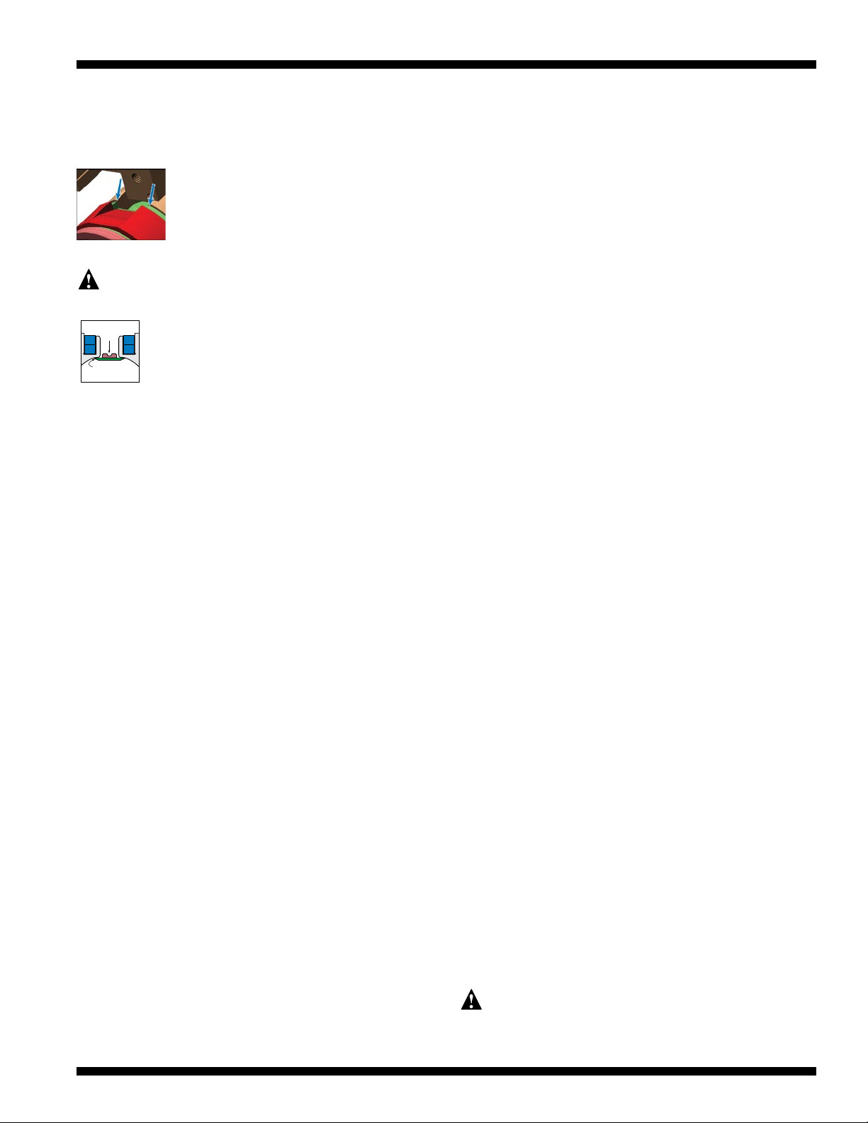
Verify surface of Piston is behind the surface of the Piston Bracket in
both places as shown in diagram.
If not aligned properly the Seal Band (4) life may be
shortened.
Install new lubricated U-Cups (8) (seal lips facing out),
and Cushion Seals (9) (small end facing out).
3. INSTALL SEALING BAND
CAUTION: Metal edges of Sealing Band are sharp. Exercise caution to
avoid injury to yourself while installing. Handle Sealing Band with care.
Do not damage edges while handling.
Insert Sealing Band (4) into Cylinder Tube (1) by laying the Band
out along the length of the actuator and passing it sideways
through the slot in Tube. With rubber side facing up (ground
side facing down), position the Seal Band so there is enough
sticking out the end of the Tube as long as a Piston Assembly.
4. INSTALL PISTON ASSEMBLY
Place generous amounts of grease around bore of Tube (1) and on exte-
rior surfaces of both Wear Rings (14) on Pistons (10), U-Cups (8) and
Band Ramps (6).
Create a Seal Band Guide Tool by using the 12-inch length of Seal Band
included with repair kit (without rubber), or cut a short length of the old
Seal Band. (Remove the rubber along the entire length of the Seal Band
Guide Tool if needed.) At one inch from one end of the Seal Band Guide
Tool, bend slightly upward. The bend helps to guide the Seal Band
Guide Tool through the Piston Assembly. Determine which end of the
Piston Assembly is going to be inserted into the Tube (1) first. Insert
the bent end of the Seal Band Guide Tool into the opposite end of the
Piston Assembly. Push the Tool through the opening between the Band
Ramp (8) and Wear Ring (14) on the Piston Bracket (5) and stopping
when the Tool exits the end of the Piston Assembly.
Place the Seal Band (4) on top of the Seal Band Guide Tool. Insert the
Piston Assembly into the Tube (1) until both U-Cups are captured by the
bore in the Tube. Do not force the Piston Bracket into the Tube and if
the Piston Assembly experiences resistance, use a small screwdriver to
press in the ends of the Band Ramps (6) where entering the Tube. Allow
the Seal Band (4) to pass through the Piston Assembly. Once the Seal
Band is though the Piston Assembly, pull the Seal Band Guide Tool out
of the Piston Assembly. Continue inserting the Piston Assembly into the
Tube until the 2nd U-Cup is inserted into the bore of the Tube.
Slide new Wipers (12) into the groove on the Piston Bracket (5) until flush
with end. Manually move the Piston Assembly the length of the Tube
until the end of the leading U-Cup extends out of the Tube. Wipe off any
excess grease from the end of the Piston Assembly and the Tube. Move
the Piston Assembly so the U-Cup back into the Tube bore.
Note: If Tube and Piston Assembly were greased properly, excess grease
should be present as the Piston exits the end of the Tube. If there is no
excess grease present, remove the Piston Assembly and re-grease the
Tube, then re-install the Piston Assembly.
5. INSTALL HEADS
CAUTION: Twisting the Head (16) during installation may cut the
O-Ring (17) resulting in excessive leakage during operation.
Install new lubricated O-Ring (17) onto each Head (16). Position Piston
Assembly near the end of the Tube in which the Head is being installed.
Position or trim the Seal Band (4) so 1.25" (31.8mm) is protruding from
the end of the Tube (1). Use a razor blade to cut the rubber along the
end of the Tube then remove all rubber outside the end of the Tube.
Keep the rubber on the Seal Band aligned with the end of the Head (16).
Install Head into Tube using a slight up and down rocking motion (not
side-to-side or twisting) until the Head is flush with the end of the Tube.
Secure Head to Tube by installing Head Screws (15) applying a torque of
190 in-lbs (21.47 N-m). Verify rubber on Seal Band (4) is still aligned
with end of Tube. If not, use needle nose pliers to pull on Seal Band
until aligned. Place Band Wedge (23) with point of Set Screw down
into slot of Head and on top of Seal Band. Push Band Wedge so it is
against the end of the Tube. Secure Band Wedge with Band Clamp (20),
FHCS (22) and Set Screws (21). Make sure hole in Band Clamp aligns
with the Cushion Needle (25) in Head.
Move Piston Assembly to other end of the Tube and repeat the steps
above to install the other head. Trim Seal Band with tin snips if needed
to achieve 1.25" (31.8mm) from end of Tube. While pulling Seal Band
tightly with needle nose pliers, use razor to cut rubber at the end of
the Tube. Remove rubber from the end of the Seal Band to the cut
just made. Install the Head (16) to the Tube and secure with the Head
Screws (15). Use needle nose pliers to pull on the Seal Band remov-
ing any slack and aligning the rubber on Seal Band with the end of the
Tube. If rubber is past end of Tube, trim excess rubber. If rubber is not
up to end of Tube, pull on Seal Band with needle nose pliers to remove
slack. Secure Seal Band with Band Clamp, FHCS and Set Screws.
Once both ends of the Seal Band are secured, manually move the Piston
Assembly the entire length of the Tube two times to see if there is any
slack or issues with the Seal Band.
6. INSTALL AND SECURE DUST BAND
Position the Piston Assembly at mid-stroke of the cylinder. Slide Dust
Band (3) through the upper slot of Piston Bracket (5) and lay on top of
the cylinder tube slot. Position the Dust Band 1.25" (31.8mm) from
each end of Tube. Install End Caps (7) using SHCS (11) into ends of
Piston Bracket (5). Loosen Set Screws (21) and FHCS (22) on both ends
of the Tube. Slide Dust Band (3) between Band Wedge (23) and Band
Clamps (20). Tighten the FHCS then the Set Screws to secure the Dust
Band. Move the Piston Assembly to each end of the Tube to verify the
Dust Band is positioned properly.
7. CHECK ASSEMBLY
Manually push the Piston Assembly back and forth along the entire
length of stroke to make certain that the cylinder is properly assembled
before reconnecting to the pneumatic supply. The Piston Assembly
should move consistently with minimal friction along the stroke. The
Dust Band should not kink at end of stroke. If it does, loosen Set
Screws (21) until kinking is eliminated and retighten.
8. INSTALL BEARING BLOCKS AND BEARING RAIL (OPTIONAL)
If you completed Step 3 in the disassembly procedure place the new
Bearing Rail (30a) on top of Nut Rail with the reference mark located on
the bottom of the Rail towards the Piston Bracket (5). Next start all the
Screws (29) that hold the Rail, but do not tighten. Center the Bearing
Rail along the length and width of the cylinder, making sure the ends of
the Rail do not cover the Heads. Also, once the Rail has been centered,
tighten all Screws (29). Slide on the new Bearing Blocks (30b) one at a
time, with the reference mark facing you.
9. INSTALL THE CARRIER
Slide the two Bearing Blocks so they are lined up with both ends of
the Piston Assembly. Place the Carrier (36) over the top of the Bearing
Blocks, guiding the Carrier around the Carrier Adjustment Plates (31).
Carefully slide the two Bearing Blocks under the Carrier (36), until the
holes from the top of the Carrier and the Bearing Blocks align. Install
Screws (35) into the Carrier and tighten.
Replace Carrier Adjustment Plates (31) and then install the Carrier
Bearing (32) into the indent on the Adjustment Blocks. Install and tighten
Screws (34) making sure Carrier is captured.
10. REMOUNT THE CYLINDER ONTO THE MACHINE
Be certain any flow controls are in place and adjusted prior to applying
compressed air to the cylinder.
RUBBER
SIDE
GROUND SIDE
Parts Sheet #8100-4117_05_MXP63Pps
Tolomatic • URL: http://www.tolomatic.com • Email: [email protected] • Fax: (763) 478-8080 • Toll Free: 1-800-328-2174
Parts Sheet #8100-4117_05_MXP63Pps
4 – Options MXP63P
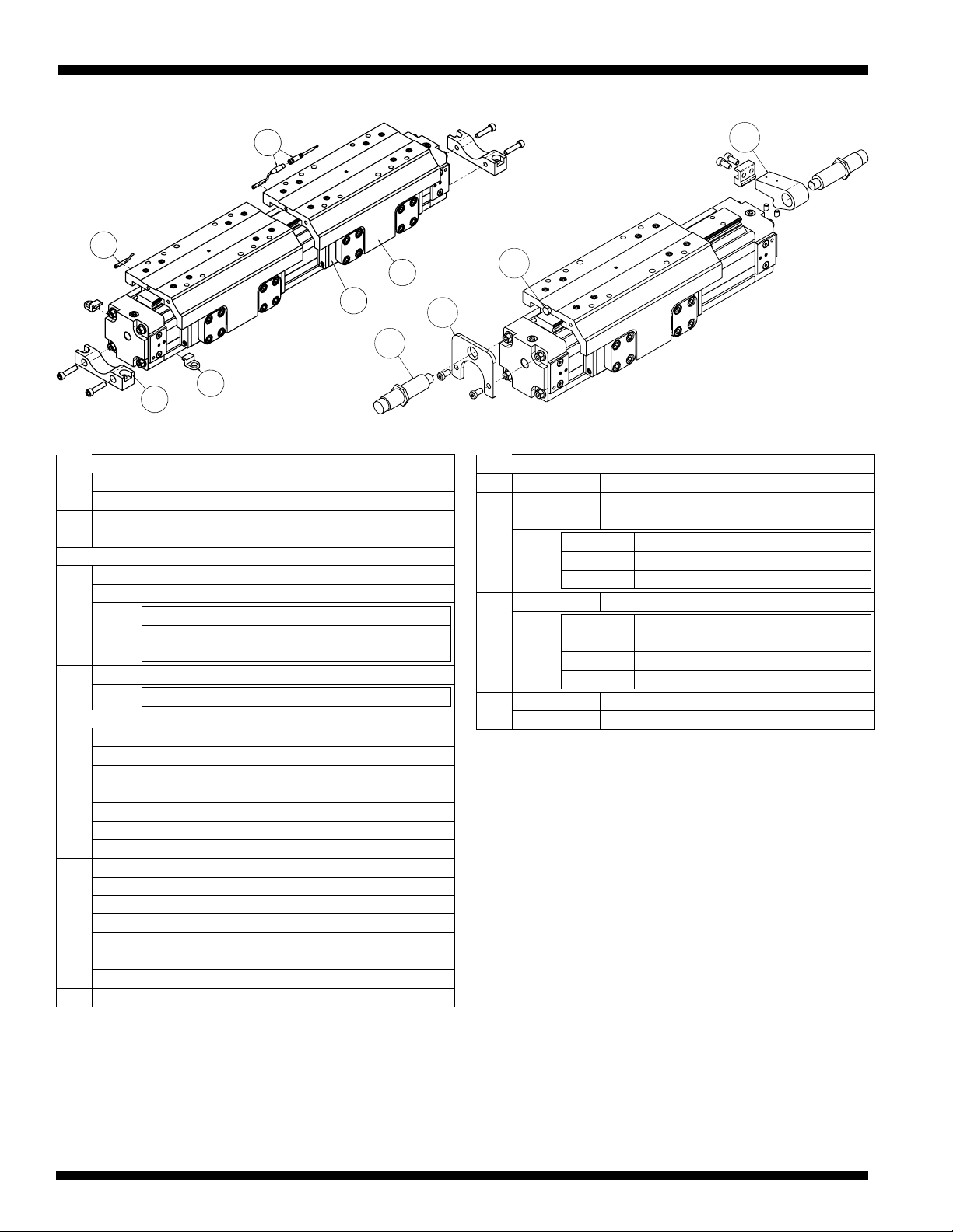
Options - List of Parts
42
41
44
43
45
46
65
63
62
64
ITEM PART NO. DESCRIPTION
AUXILIARY CARRIER
41 8163-9504 Auxiliary Carrier Assembly (inch)
8163-9004 Auxiliary Carrier Assembly (metric)
42 8163-9528 Auxiliary Carrier Piston Bracket Assembly (inch)
8163-9028
Auxiliary Carrier Piston Bracket Assembly (metric)
MOUNTING KITS
432
8163-9519 Foot Mount Kit (inch)
8163-9019 Foot Mount Kit (metric)
8163-1055 Foot Mount
1104-1011 Screw (inch)
3420-1638 Screw (metric)
4418163-9018 Tube Clamp Mounting Kit
8163-1050 Tube Clamp
SWITCHES
45
Switches without Quick-Disconnect Couplers
SWMXP63 RY Reed Switch, SPST Normally Open
SWMXP63 NY Reed Switch, SPST Normally Closed
SWMXP63 TY
Solid State Switch, PNP (sourcing) Normally Open
SWMXP63 KY
Solid State Switch, NPN (sinking) Normally Open
SWMXP63 PY
Solid State Switch, PNP (sourcing) Normally Closed
SWMXP63 HY
Solid State Switch, NPN (sinking) Normally Closed)
46
Switches with Quick-Disconnect Couplers
SWMXP63 RK Reed Switch, SPST Normally Open
SWMXP63 NK Reed Switch, SPST Normally Closed
SWMXP63 TK
Solid State Switch, PNP (sourcing) Normally Open
SWMXP63 KK
Solid State Switch, NPN (sinking) Normally Open
SWMXP63 PK
Solid State Switch, PNP (sourcing) Normally Closed
SWMXP63 HK
Solid State Switch, NPN (sinking) Normally Closed
NOTE: Female Connector for Quick-Disconnect is included
ITEM PART NO. DESCRIPTION
SHOCK ABSORBERS
62 4415-1003 Impact Bolt
634
8163-9520 Fixed Shock Mounting Kit (inch)
8163-9020 Fixed Shock Mounting Kit (metric)
8163-1060 Fixed Shock Bracket
2317-1015 Screw (inch)
8163-1061 Screw (metric)
645
8163-9024 Adjustable Shock Mounting Kit
8163-1084 Shock Bracket
8163-1086 Shock Bracket Clamp
2212-1104 Socket Head Cap Screw
8125-1035 Dowel Pin
65 4920-1068 Light Duty Shock Absorber
4920-1069 Heavy Duty Shock Absorber
1Tube Clamp Kit contains 2 tube clamps.
2Foot Mount Kit contains 1 foot mount and 2 fasteners.
3Floating Mount Kit contains 1 floating mount, 1 lower strap, 1 pin and 4
fasteners.
4Fixed Shock Mounting Kit contains 1 shock bracket, and 2 fasteners.
5Adjustable Shock Mounting Kit contains 1 shock bracket, 2 bracket clamps,
and 4 fasteners.
3800 County Road 116, Hamel, MN 55340
http://www.Tolomatic.com • Email: Help@Tolomatic.com
Phone: (763) 478-8000 • Fax: (763) 478-8080 • Toll Free: 1-800-328-2174
8
© 2017 Tolomatic 201702060827
Information furnished is believed to be accurate
and reliable. However, Tolomatic assumes no
responsibility for its use or for any errors that
may appear in this document. Tolomatic reserves
the right to change the design or operation of the
equipment described herein and any associated
motion products without notice. Information in
this document is subject to change without notice.
Parts Sheet #8100-4117_05_MXP63Pps
MXP63P Switches / Maintenance – 5
Parts Sheet #8100-4117_05_MXP63PpsParts Sheet #8100-4117_05_MXP63Pps
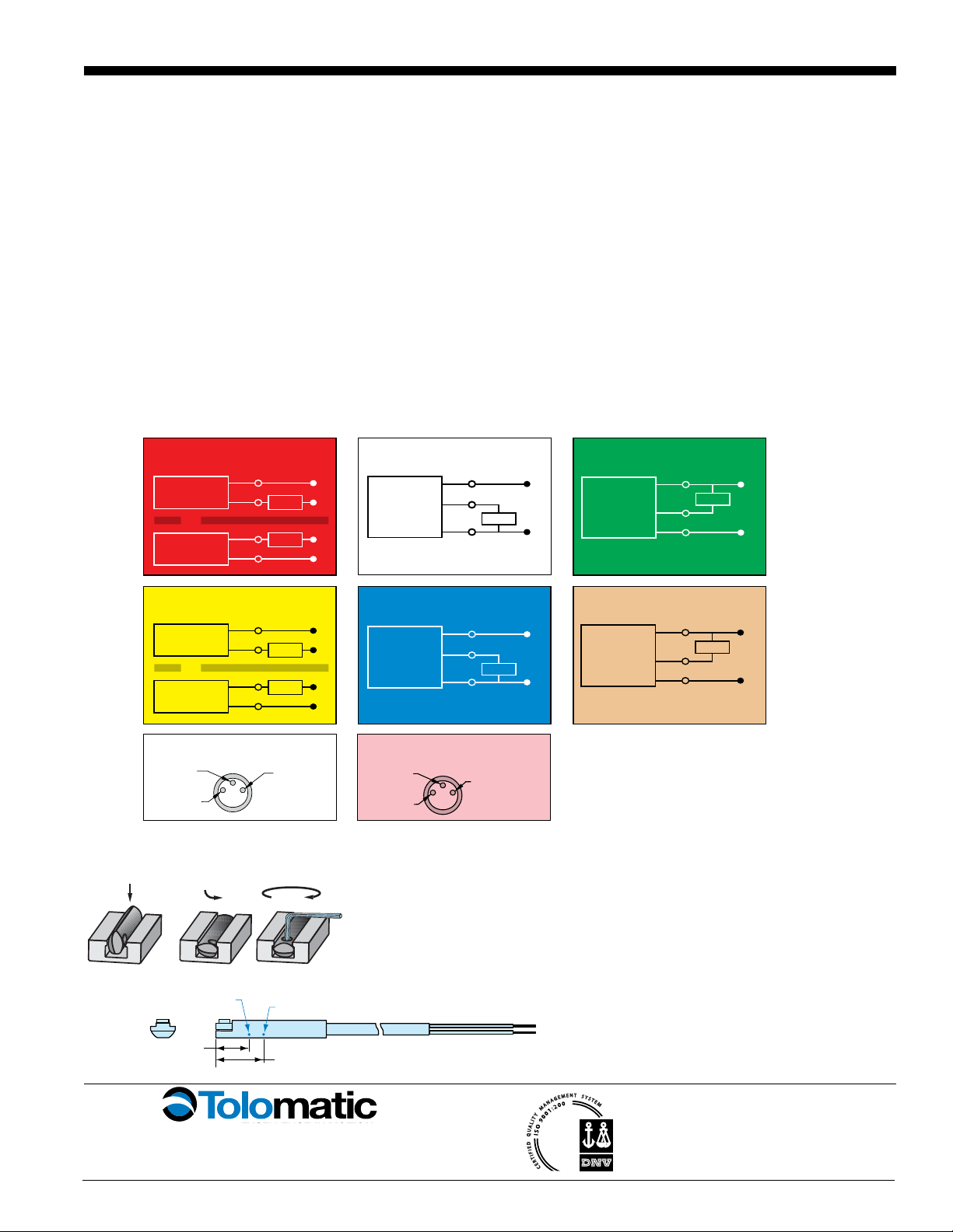
SWITCH WIRING DIAGRAMS AND LABEL COLOR CODING (CE and RoHS Compliant)
NORMALLY
CLOSED
BRN
BLU
+
-
LOAD
NORMALLY
CLOSED
BRN
BLU
+
-
LOAD
or
NORMALLY
OPEN PNP
(SOURCING)
BRN
BLK
+
SIGNAL
LOAD
BLU
-
NORMALLY
OPEN NPN
(SINKING)
BRN
BLK
+
SIGNAL
LOAD
BLU
-
NORMALLY
CLOSED PNP
(SOURCING)
BRN
BLK
+
SIGNAL
LOAD
BLU
-
NORMALLY
CLOSED NPN
(SINKING)
BRN
BLK
+
SIGNAL
LOAD
BLU
-
NORMALLY
OPEN
BRN
BLU
+
-
LOAD
NORMALLY
OPEN
BRN
BLU
+
-
LOAD
or
TY • TK
SOLID STATE • NORMALLY OPEN • PNP
NY • NK
REED • NORMALLY CLOSED
QUICK DISCONNECT MALE PLUG PINOUT #8100-9080 QUICK DISCONNECT
FEMALE SOCKET PINOUT
RY • RK
REED • NORMALLY OPEN
KY • KK
SOLID STATE • NORMALLY OPEN • NPN
PY • PK
SOLID STATE • NORMALLY CLOSED • PNP
HY • HK
SOLID STATE • NORMALLY CLOSED • NPN
BROWN (+)
BLUE (-)
BLACK
(SIGNAL)
BLUE (-)
BROWN (+)
BLACK
(SIGNAL)
SWITCH DETECTION POINT
16, 25, 32
MOUNTING DIMENSIONS
SWITCH DIMENSIONS
40, 50, 63
1.18 [30]
.31 [8]
Ø.28 [7]
.95 [24.1]
1.26 [32.1]
.51 [13]
DETECTION POINT REED
DETECTION POINT
SOLID STATE
13.35 [339]
M8x1
M8x1
197 [5000]
197 [5000]
_K- QD (Quick-disconnect) switch
8100-9080 - QD Cable
_Y- direct connect
U
SWITCHES SIT BELOW
TUBE EXTRUSION PROFILE
SWITCHES SIT BELOW
TUBE EXTRUSION PROFILE
V
U
Ø.35
[9]
W
V
X
Switches for MX:
• Include retained mounting hardware
• In slot, sit below extrusion profile
• Same for all sizes and bearing styles
LUBRICATION AND MAINTENANCE
All Tolomatic MX Band Cylinders are prelubricated at the factory. To ensure
maximum cylinder life, the following guidelines should be followed.
1. Filtration
We recommend the use of dry, filtered air in our products. “Filtered
air” means a level of 10 Micron or less. “Dry” means air should be
free of appreciable amounts of moisture. Regular maintenance of
installed filters will generally keep excess moisture in check.
2 External Lubricators (optional)
The factory prelubrication of Tolomatic Band Cylinders will provide
optimal performance without the use of external lubrication. However,
external lubricators can further extend service life of pneumatic
actuators if the supply is kept constant.
Oil lubricators, (mist or drop) should supply a minimum of 1 drop per
20 standard cubic feet per minute to the cylinder. As a rule of thumb,
double that rate if water in the system is suspected. Demanding con-
ditions may require more lubricant.
If lubricators are used, we recommend a non-detergent, 20cP @
140˚F 10-weight lubricant. Optimum conditions for standard cylinder
operation is +32˚ to +150˚F (+0˚ to 65.5˚C).
NOTE: Use of external lubricators may wash away the factory installed
lubrication. External lubricants must be maintained in a constant sup-
ply or the results will be a dry actuator prone to premature wear.
3. Sanitary Environments
Oil mist lubricators must dispense “Food Grade” lubricants to the air
supply. Use fluids with ORAL LD50 toxicity ratings of 35 or higher
such as Multitherm®PG-1 or equivalent. Demanding conditions can
require a review of the application.
4. Cushion Adjustment
Adjust the Cushion Needles in the Cylinder Heads carefully to obtain
optimum deceleration for your particular application. If there are
questions on proper adjustment, please consult Tolomatic.
SWITCH INSTALLATION AND REPLACEMENT
Place switch in side groove on tube at desired location with "Tolomatic" facing
outward. While applying light pressure to the switch, rotate the switch halfway
into the groove. Maintaining light pressure, rotate the switch in the opposite
direction until the switch is fully inside the groove with "Tolomatic" visible.
Re-position the switch to the exact location and lock it securely into place by
tightening the screw on the switch.
Insert
switch
Rotate
switch
Secure
switch
Tolomatic
Tolomatic
Tolomatic
Dimensions in inches [brackets indicate dimensions in millimeters]
This manual suits for next models
5
Other Tolomatic Industrial Equipment manuals

Tolomatic
Tolomatic Band Cylinder BC2 Series User manual

Tolomatic
Tolomatic BC4 Series User manual

Tolomatic
Tolomatic TC15 User manual

Tolomatic
Tolomatic TC07SS Use and care manual

Tolomatic
Tolomatic MXP25PTP User manual

Tolomatic
Tolomatic MXP32N Series Use and care manual

Tolomatic
Tolomatic MXP50N User manual

Tolomatic
Tolomatic MXP16N User manual

Tolomatic
Tolomatic BC3 Series User manual

Tolomatic
Tolomatic Band Cylinder BC2 Series User manual


