Tormach ATC User manual
USING THE TORMACH
TOOLING SYSTEM ATC
AUTOMATIC TOOL CHANGER
FOR THE PCNC 1100
Operator’s Manual
© 2013 Tormach®LLC. All rights reserved.
Questions or comments?
Please e-mail us at:
Tormach TTS ATC Manual:
UM10081_TTS_ATC_PCNC1100_1013A


1. Preface 2
1.1 Manual Overview 2
1.2 Safety 2
1.3 System Requirements 3
2. Preparaon 4
2.1 UnpackingandCheckingShipment 4
2.2 BeforeYouBegin 5
2.3 MounngtheATC 5
3. ElectricalInstallaon 7
4.1 AirLineConneconandRequirements 12
4. AirLines 12
5. SowareInstallaon 14
6. SystemValidaon 15
6.1 AlignToolTrayandSlots 16
7.1 FootPedalKit 20
7.2 FilterRegulatorLubricator(FRL) 20
7. OponalAccessories 20
7.3 PressureSensor 21
8. Operaon 23
8.1 GeneralTheoryofOperaon 23
8.2 Loading/UnloadingTools 23
8.3 AutomacTrayLoad/Unload 24
8.4 ManualTrayLoad/Unload 24
8.5 ToolTouch-oRoune 25
8.6 ATCBypass 25
9. Maintenance&Troubleshoong 26
9.1 Support 26
9.2 Maintenance 26
9.3 Troubleshoong 26
10. ExplodedView&PartsList 33
10.1 ATCCarousel 34
10.2 ATC1100ColumnMount 36
10.3 TTSATCActuator 38
10.4 ATCControlModuleAssembly 40
10.5 TTSATCPneumacSchemac 42
10.6 ATCElectrical 43
TABLE OF CONTENTS
PB 1
UM10081_TTS_ATC_PCNC1100_1013A UM10081_TTS_ATC_PCNC1100_1013A

1.1 Manual Overview
ThismanualisintendedforusersoftheTormachTooling
SystemAutomacToolChanger-anaccessorytothe
TormachPCNC1100mill.Readersareassumedtobe
familiarwiththeoperaonanddocumentaonfortheir
parcularmillingmachine.Forquesonsofageneral
nature(e.g.applyingtoolheightosetcompensaon)
pleaserefertothePCNC1100machinemanual.
TheTTSATCcanbeusedwithallexisngpartprograms
withoutmodicaon,regardlessofexisngtoolnumber
assignments.Forprogramsthatuse10toolsorfewerthe
ATCmaybeusedforalltoolchanges.Forpartprograms
requiringmorethan10tools,orforprogramsrequiring
specialtoolingnotappropriateforanATC,suchasa
reversingtappinghead,itcanbeusedinconjunconwith
manualchanges.Anytoolnumberbetween1and253
maybeassignedtoaposioninthetooltray–youarenot
connedtousingtoolnumbers1-10.Thisisconvenientif
youhaveatoollibraryalreadysetupwithtoolnumbers
andheightsmeasuredinyourtoolosettable.The
toolchangerrememberstoolsassignedtothetray,and
promptsformanualspindleinseronandremovalofnon-
assignedtoolsatappropriatemes.Toolsmaybeassigned
todierenttraynumberssothat,forinstance,onecan
dedicategroupsoftrayassignmentstospecicjobsthat
are run frequently.
AlltoolsarecalledfromGcodewithstandardM6
commands,orfrombuonsontheATCcontrolscreen.
1.2 Safety
Anymachinetoolispotenallydangerous,
especiallyautomatedtoolsundercomputer
control.BecauseTormachdoesnotknow
thedetailsofyourworkshoporotherlocal
condions,noresponsibilitycanbetakenfordamage
orinjurycausedbytheuseofthemillandATC.Itisthe
owner’sandoperatorsresponsibilitytounderstandthe
mill/ATCsystemintegraonandoperaonandtocomply
withanylegislaonandcodesofpracceapplicableto
countryorstate.Ifthereisanydoubt,seekguidancefrom
aprofessionallyqualiedexpertratherthanriskinjury.
ThesafetyofanyapplicaonusingtheATCisulmately
theresponsibilityofthoseperformingthesetupand
operaon.Pleasedonottakethisresponsibilitylightly
-usecommonsenseandreviewallinstruconsonthe
operaonandmaintenanceoftheATC
Operator Safety
• Whenusingelectrictools,machinesorequipment,
basicsafetyprecauonsshouldalwaysbefollowed
toreducetheriskofre,electricshock,andpersonal
injury.
• Readandunderstandthismanual.Donotoperatethe
ATCwithoutknowingthefunconofeverycontrol
key,buon,andalignmentandreferencingprocedure.
RefertothismanualorcontactTormachifanyfuncon
isnotunderstood.
• KeephandsclearoftheATCatallmesduringtool
changesorwhencommandinganyATCmoonfrom
theATCcontrolscreenofthemill’scontrolsoware.
• Avoidcontactwithmovingparts.Beforeoperangthe
millandATC,removealljewelryincludingwatchesand
rings,neckesandanyloose-ngclothing.Tieback
hair.
• Keephairawayfrommovingparts.
• Donotreachforthepart,toolorxturewhilerunning
apartprogram.
• Keepworkareaclean.Clueredareasinviteinjuries.
• WearANSIapprovedeyeproteconatallmes.
• Keepworkareawelllit.
• Keepthecomputerareaclearofcluer.
• Neveruselongerorlargertoolsthannecessary.
• DonotusetheATCorpowertoolsindamp,wetor
poorlylitlocaons.
• Donotusetoolsinthepresenceofammablegasesor
liquids.
• Useonlyidencalreplacementpartswhenservicing.
• TakeoglovesbeforeyouoperatetheATC.Glovesare
easilycaughtinmovingpartsorcungtools.
• Neveroperatewithunbalancedtooling.
• NeveroperatetheATCaerconsumingalcoholic
beveragesortakingstrongmedicaon.
• Protectyourhands.Stopthemachineandensurethat
thecomputercontrolisstoppedbeforeyou:
*Changetools;
*Changepartsoradjusttheworkpiece;
*Makeanadjustment;
• Keepworkareawelllit.Askforaddionallightif
needed.
• Alwaysuseproperfeedsandspeeds,aswellasdepth
andwidthofcut,topreventtoolbreakage.
• Usepropercungtoolsforthejob.
• Donotusedullordamagedcungtools.Theybreak
easilyandbecomedangerousprojecles.
• Becertaineveryoperatorunderstandstheoperaon
andsafetyrequirementsofthemillandATCbefore
operang.Itistheresponsibilityoftheownerof
1. PREFACE
23
UM10081_TTS_ATC_PCNC1100_1013A UM10081_TTS_ATC_PCNC1100_1013A

theATCtoprovideandensurepointofoperaon
safeguardingperOSHAstandards.
Electrical Safety
TheTormachToolingSystemATCoperateson
70VDC,fusedat8amps.Itispoweredfrom
theDCBusBoard(PN32005)insidethecontrol
cabinetofthemill.Neveroperatethe
machinetoolwiththecabinetdooropen.Nevermakeor
checktheseconneconswiththemillpoweredon.
PowertotheATCandotherdevicesinsidethecontrol
cabinetmayretaindangerousvoltagesaerexternal
powerhasbeenremoved.Donotmodifythese
conneconsinanyway.Ifunsureabouttheconnecons,
callTormachoraqualiedrepairtechnician.
1.3 System Requirements
TousetheTormachToolingSystemATC,yourmachine
mustmeetthefollowingrequirements:
• Youmustprovideacompressedairsourcecapableof
deliveringclean,dryairat95PSIand2CFM.
• TheTormachPowerDrawBar(PN31706)mustbe
installed
• ForPCNC1100machinesserialnumbers1325and
lower,youmusthavepreviouslyinstalledtheSpindle
DriveUpgradekit(PN31090)
• ForPCNC1100machinesserialnumbers999and
lower,youmusthavepreviouslyinstalledtheSeries3
upgradekit(PN32010)
Required Tools
• MetricAllenwrenchset
• Screwdrivers
• Boxwrenchesandlargecrescentwrench
• Hotgluegun
• 12”longwoodendowelorroundstock
23
UM10081_TTS_ATC_PCNC1100_1013A UM10081_TTS_ATC_PCNC1100_1013A
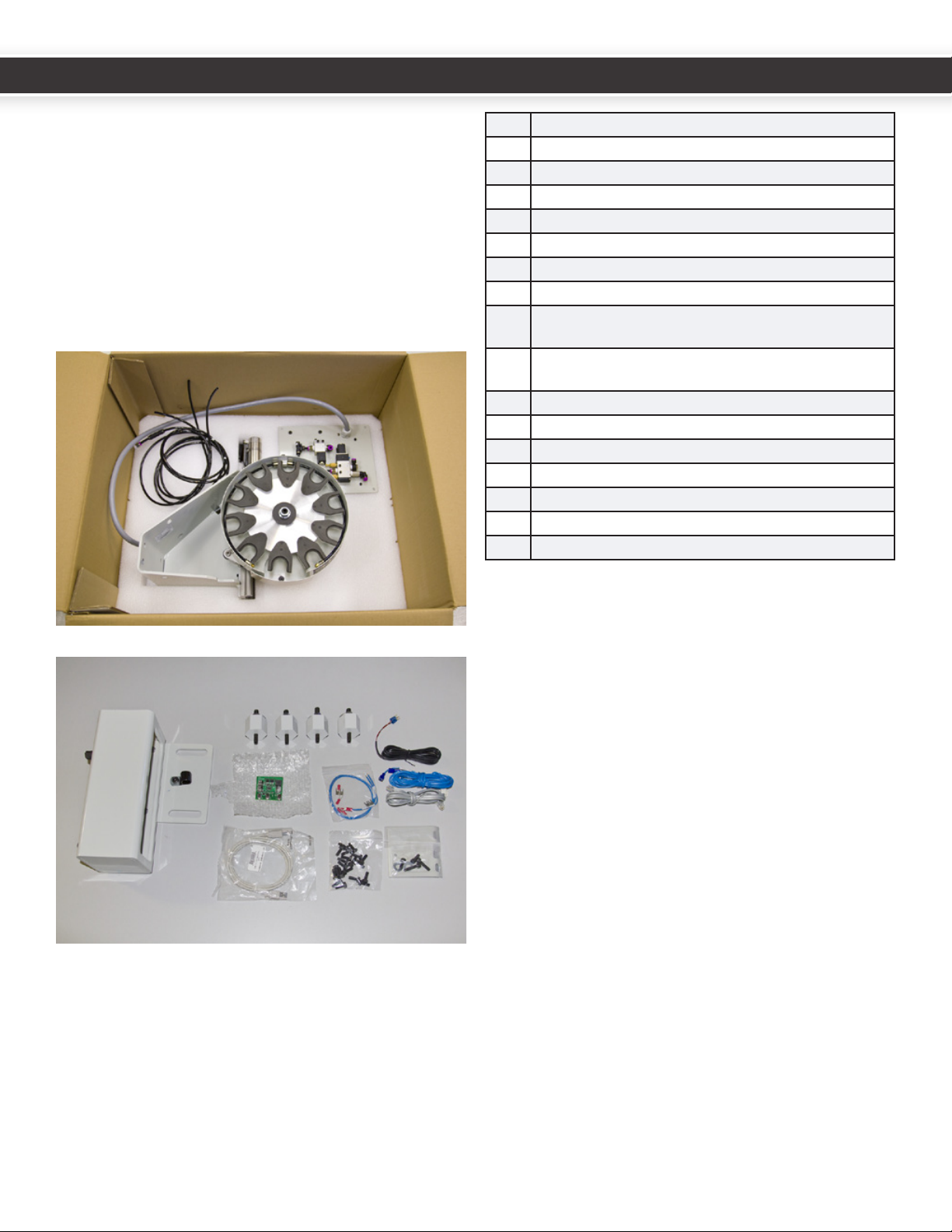
2.1 Unpacking and Checking
Shipment
Uponreceipt,carefullyunpacktheATCandinspectto
ensuredamagedidnotoccurintransitandalsotoaccount
forallparts.Ifanydamageisapparent,orpartsmissing,
pleasecontactTormachimmediately.
Withanassistant,litheATContoasturdysurfaceor
workbenchtoprepareitforuse.
11ATCassembly
24¼”airlines,onew/checkvalveandpushng
31ATCsquaretubemount
4 4hexstandoswithM8andM10studs
5 4angenutsandwashers
620nylonM6x16hexbolts
7 1USBcable
81ATCcommunicaonRJ-11cable(512-515)
91Mainpowercable(503,504)terminatedwith4pin
Molexandspades
10 1PDBpowercable(501,502)terminatedwithPDBcon-
nectorandspades
11 1VFDinterconnectwiringkit(532-535)
12 1coolanthosemounngplatew/fasteners
13 PowerDrawBarpowersupplyboard
14 1R8TTSexpandedcollet
15 Operator’sManual
16 SowareinstallaonCD
17 25X20glassfuses
Thefollowingitemsmayormaynotbeincludedbasedon
theageofyourmachineandpowerdrawbarinstallaon:
1. 1drawbarwith8Bellevillewashers
2. PowerDrawbarcontrolcircuitboard(ifrequiredbased
onageofyourpowerdrawbarinstallaon.)
3. DCBusBoard
Checktheseitems.NofyTormachofanydamageincurred
duringtransitormissingpartssoanyclaimscanbemade
withintheshippingcarrier’sdeadline.
2. PREPARATION
45
UM10081_TTS_ATC_PCNC1100_1013A UM10081_TTS_ATC_PCNC1100_1013A

2.2 Before You Begin
TheTormachToolingSystemATCisdesignedformachines
withthepowerdrawbar(PN31706)installed.PCNC1100
millingmachineswithserialnumbers1325andlower
willneedtohavethespindledriveupgrade(PN31090)
installedbeforeinstallingtheATC.PCNC1100machines
withserialnumbers999andlowerwillalsohavetohave
theSeries3upgradekit(PN32010)installedbefore
installingtheATC.
Allmachineswillneedtohavethepowerdrawbarinstalled
beforeinstallingtheATC.Seethepowerdrawbarmanual
(includedwiththepowerdrawbarpackageandontheATC
sowareCD)forpowerdrawbarinstallaoninstrucons.
PCNC1100machinesserialnumbers1999andlowerwill
needtoreplacetheoldDCBusBoard(PN30661)withthe
newbusboard(PN32005).
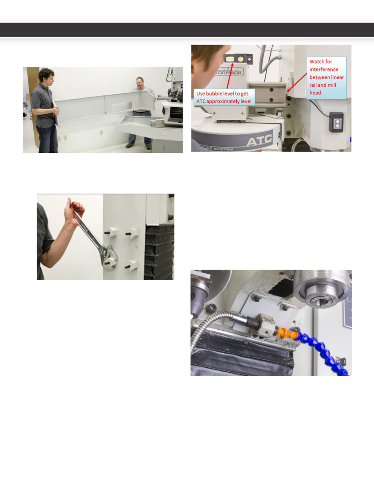
2.3 Mounting the ATC
MounngandaligningtheATCtothemillisajobthatis
bestdonewithtwopeople.TheATCcarouselassembly,
whichweighsapproximately50pounds,iscumbersometo
liandposionaccuratelyespeciallywhenworkingover
themill’schiptray.Installaongoessmoothlywhenone
personholdstheATCinposionwhileanassistantghtens
thefastenersthatconnectittothesquaretubemount.
Initial Hardware Installation
WARNING! SHUT THE COMPUTER
DOWN, THEN POWER DOWN THE MILL
USING THE ROTARY SHUTOFF SWITCH
ON THE RIGHT HAND SIDE OF THE
CONTROL CABINET.
Youmayndinstallaoneasiestifyourstpullthemill
awayfromthewall.
Ifed,removethecoolanthoseandmountfromthe
spindle head.
Ifed,removethelehandmachinearmfromthemill
column.
45
UM10081_TTS_ATC_PCNC1100_1013A UM10081_TTS_ATC_PCNC1100_1013A
Ifed,removetheuppercoolantsplashguards
(backsplash)fromtheleandrighthandchiptrays.
1. ThreadtheM8sideofhexstandosintomillcolumn
andghtensecurelywithawrench.
2. HangthetoolchangersquaretubemountontheM10
studs.Securewithangenutsandwashers.Theslots
arewiderthanthestudtoallowforminordeviaons
inholelocaons,andtofacilitateasmalldegreeoflt.
3. Withtheassistanceofanotherperson,fastentheATC
tothemountusingthe4M10socketheadcapscrews
andangenuts.
4. Duetostackupofparttolerances,exibility,and
backlashinthelinearbearings,thechangermight
seleslightly,orsagfromhorizontalonitsmounng
system.Thisisnormal.Compensateforminorsagby
lngthemountslightlysothetooltrayappearslevel
usingabubblelevel.
Note: Be sure to adjust the mount so that the mill
spindle cover sheet metal clears the ATC linear rail.
5. Reroutethecoolanthosebymounngthecoolant
hoseclamptotheincludedcoolantplate.Aachthe
platetotheundersideofthespindleheadusingthe
twothreadedholesontheundersideofthespindle
headcasng.
67
UM10081_TTS_ATC_PCNC1100_1013A UM10081_TTS_ATC_PCNC1100_1013A
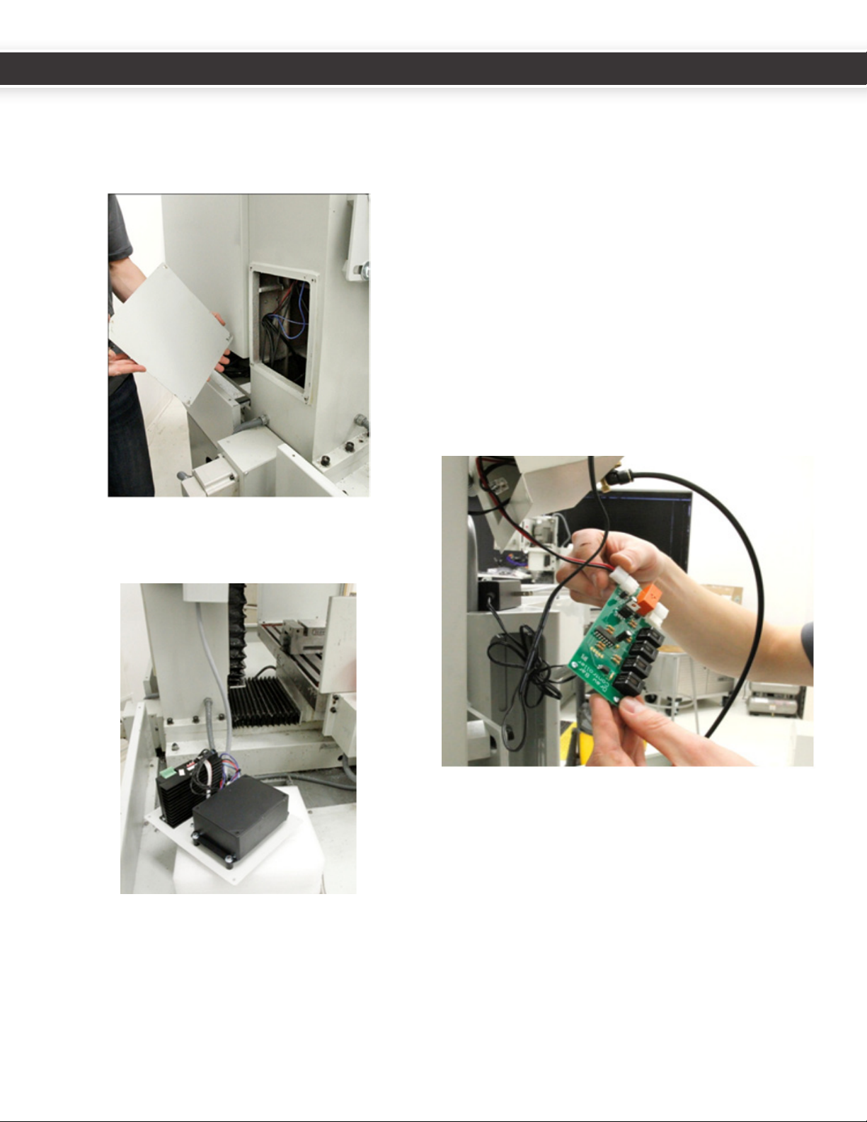
3. ELECTRICAL INSTALLATION
1. Removethefourcolumncoverplatescrewsfrombase
ofcolumnatthebackofthemill.TheZcolumncover
platewillbereplacedwiththeATCcontrolmodule.
Save the screws.
2. LaytheATCcontrolmoduleplatewithsolenoid
sidedownonthechiptrayortheYaxisbearingbox
temporarily.
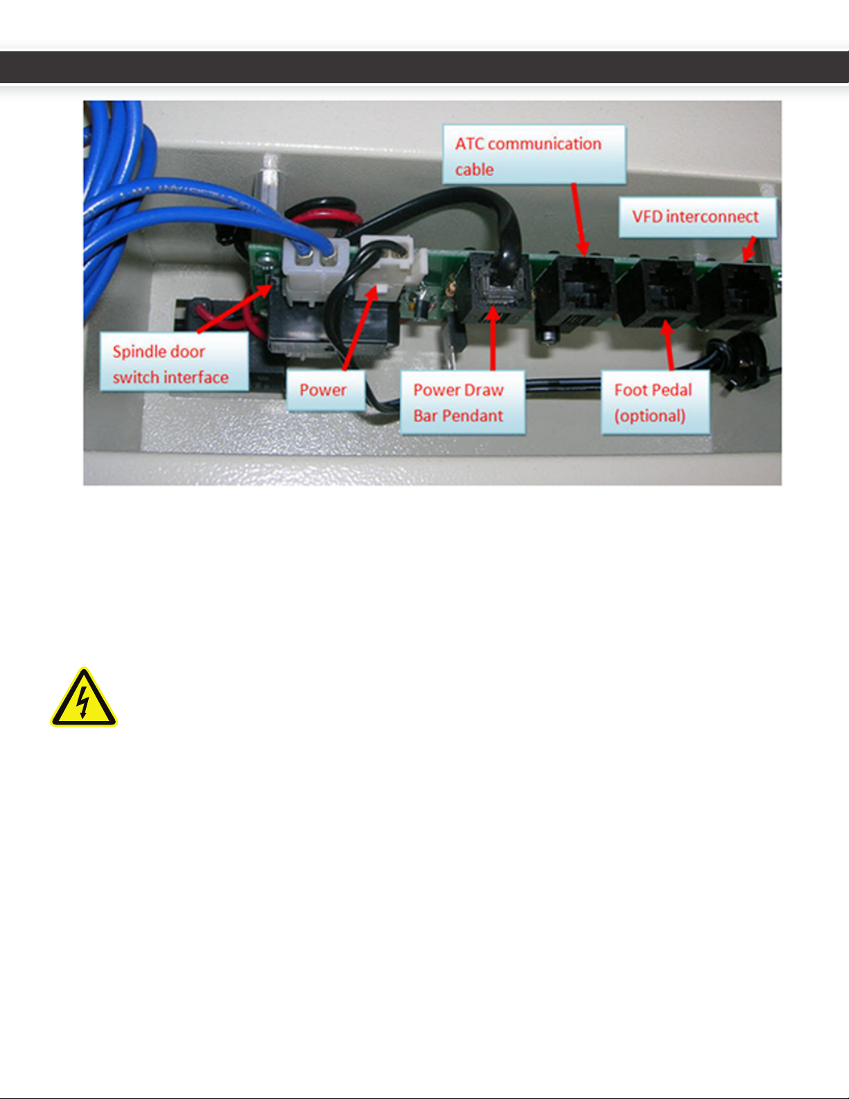
3. Removethepowerdrawbarelectricalhousing(Zaxis
motorconneconboxcoverplate).
Bar control circuit board.
CircuitboardslabeledRev1.2willneedtobereplaced.In
thiscaseTormachshouldhaveincludedtheupdatedcircuit
boardwithyourATC.
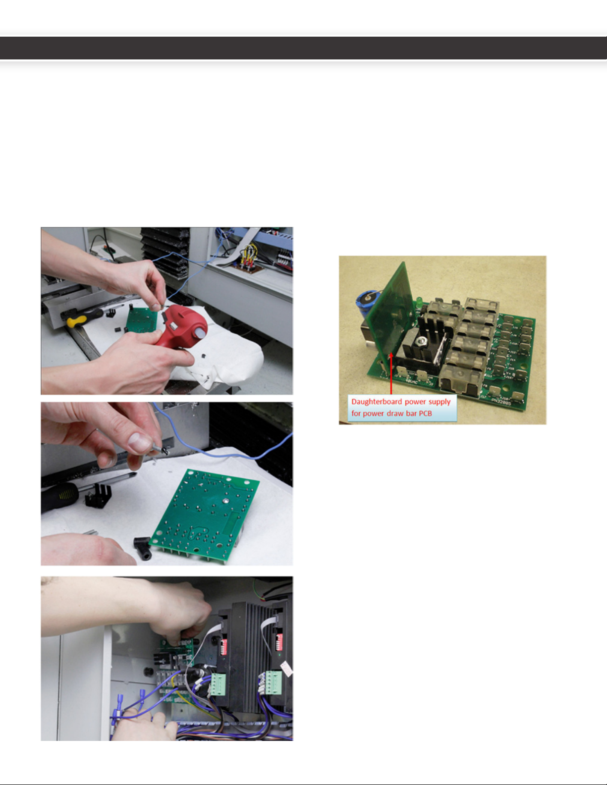
• Toreplaceanold(Rev1.2orearlier)circuitboard,
disconnectandremovetheoldcircuitboard,taking
noteofthelocaonsoftheconnectors.Whilenot
necessary,youmaynditeasiertoremovetheair
linesandthecablecarrieraswell.
• Replacetheolddrawbarboardwiththenewone.
Itiseasiesttoreplacethesolenoidleads(redand
blackwire)beforere-mounngthecircuitboard.The
solenoidleadsgototheoppositesideofboardfrom
otherconnectors.Thisistheonlyconnectoronthat
side(2pinnylon).
ConnecttheblackVFDinterconnectRJ11cable(withthe
spadeterminalends)totheDB1connectoronthepower
drawbarcontrolboard,andtheATCcommunicaonRJ11
cabletotheDB3connectorasshowninthefollowing
gure.
67
UM10081_TTS_ATC_PCNC1100_1013A UM10081_TTS_ATC_PCNC1100_1013A
4. Removetheold“wallwart”powerconnectorandreplaceitwithwires501,502.Thesewireswillberoutedtothe
newDCBusBoard,andyouwillbeabletothrowoutthewallwartpowersupply.
supply.
5. Routeallwires(thetwoRJ11cables,thebluespindledoorswitchinterfacewires,andthepowerwires503,504)
throughthemillcolumn.
COLUMN. THESE WIRES CARRY 110V AC AND IN RARE CASES CAN CAUSE EMF THAT
DISTURBS USB SIGNAL TRANSMISSION WHEN THEY ARE NOT TWISTED. TWISTING THE
WIRES CANCELS THIS EMF.
89
UM10081_TTS_ATC_PCNC1100_1013A UM10081_TTS_ATC_PCNC1100_1013A

6. Re-securethedrawbarelectricalhousingtotheZaxis
motorconneconboxcoverplate).
7. ConnecttheATCcommunicaonRJ11cable(fromthe
DB3connectoronthepowerdrawbarcircuitboard)
andtheUSBcabletotheATCcontrolboard.
8. DropanyslackwiresfromtheATCcontrolmoduleinto
theZcolumn,andsecuretheATCcontrolmoduleto
thebackofthemillusingthesavedM5screwsand
intoexisngcolumnholes.Besurethatextrawire
slackdoesnotcontacttheYaxisballscrew.
9. RoutetheUSBcablethroughtheboomholeofthe
electriccabinetintoanyPCUSBport.
CAUTION! DO NOT CONNECT THE USB
CABLE TO THE COMPUTER UNTIL AFTER
THE SOFTWARE INSTALLATION IS
COMPLETE.
your electrical cabinet to route the USB cable to your
control computer.
10.RuntheblueATCcontrolboardpowerleads(503,504)
andthepowerdrawbarcircuitboardpowerleads
(501,502)throughthewirechannelsfromtheholeto
thebusboardatthetopofthecabinet.
11.Series31100machinescomewiththecorrectDCBus
BoardforusewiththeATC.Series3ownerscanskip
steps12-13.Domakesuretoinstallthe5x20mmfuses
intheDCBusBoardATCandPDBfuseholders.This
appliestoallmodelmachines.
89
UM10081_TTS_ATC_PCNC1100_1013A UM10081_TTS_ATC_PCNC1100_1013A
12. PCNC 1100 MACHINES SERIAL NUMBERS 1999 AND
LOWER: ReplacetheoldDCbusboard(PN30661)with
thenewbusboard(PN32005).Ensureallfusesare
presentontheDCBusBoardbeforeinstallaon(there
shouldbenoemptyfuses).WhenremovingtheoldDC
busboard,catchthestandosandsavethescrews.
Replacewiththenewboardonthesamestandos.
Itisextremelyhelpfultotackgluethestandosin
placebeforemounngtheboard.Aneasywaytodo
thisistoputadabofhotglueonthefastenersbefore
inserngthemthroughtheboardholesandstandos.
13.Double-checkthepolarityofthecapacitor,stepper
driver,andATCconneconsbeforepoweringupthe
machine.Reversingpolaritywilldestroythestepper
driversandATCcontrolboard.
14.Installthepowerdrawbardaughterboardpower
supply(PN31980)byslidingitontothespade
connectorsonthenewDCbusboard(PN32005).This
boardsuppliesthe12Vneededbythepowerdrawbar,
andwillallowyoutothrowawaythewallwartpower
supplythatcamewiththepowerdrawbar.
15.RoutetheRJ11VFDinterconnectcablealongthe
boomwiretraytotheVFD.RemovetheVFDcover
byunscrewingthePhillipsfasteneronthefaceofthe
coverplate.
10 11
UM10081_TTS_ATC_PCNC1100_1013A UM10081_TTS_ATC_PCNC1100_1013A
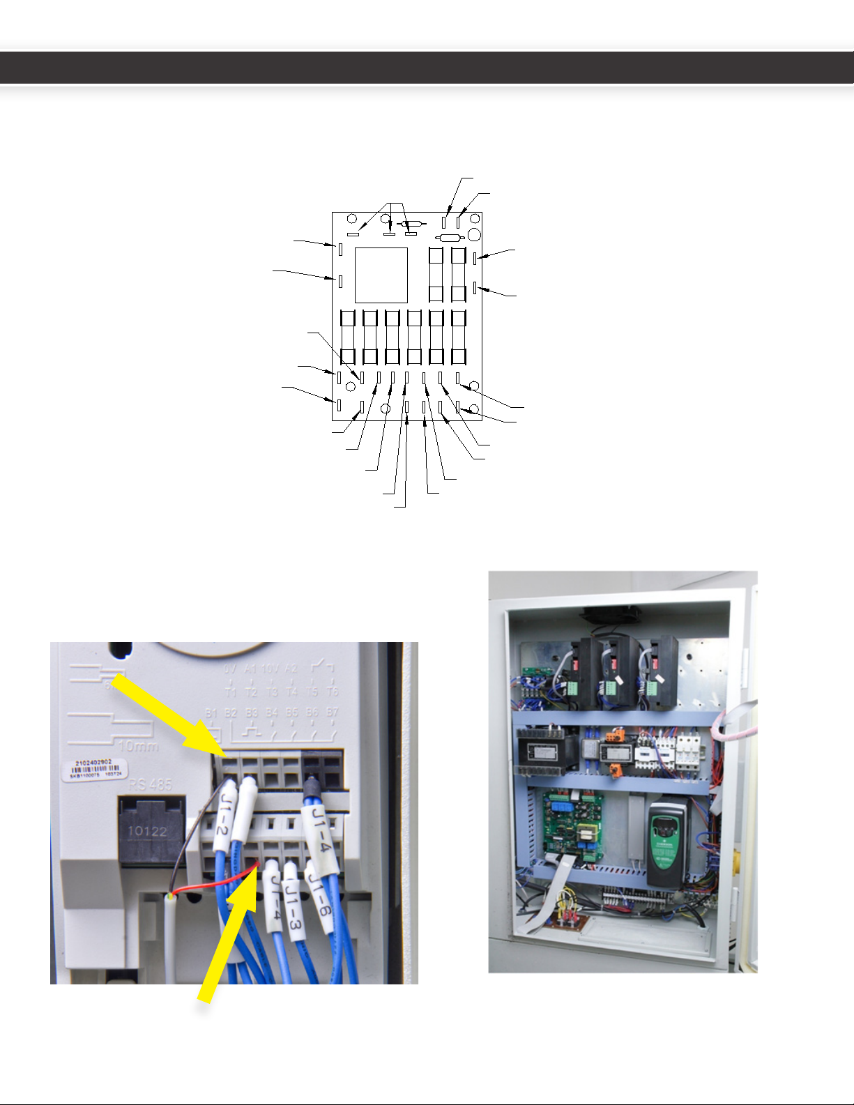
32005 DC BUS
Lables and wire numbers
X+ 302
X- 303
Y+ 304
Y- 305
Z+ 306
Z- 307A+ 324
A- 325
BRAKE RLY+ 328
BRK- 327
BRAKE RLY- 329
BRK+ 326
J2-48VAC L15
J1-48VAC L25 CAP- 300
CAP+ 301
8 A
8 A
8 A
8 A
2 A
8 A
15 A
8 A
503 Optional ATC +
504 Optional ATC -
501 Optional PDB -
502 Optional PDB +
DAUGHTERBOARD
FOR OPTIONAL PDB
F1 = X AXIS
F2 = Y AXIS
F3 = Z AXI
F4 = A AXIS
F5 = DC BRAKE
F6 = MAIN
F7 = PDB
F8 = ATC
F7
F6
F1
F2
F3
F4
F5
F8
S
16.InserttheblackandredwiresoftheRJ-11cableinto
posionsT1andB3ontheVFDfor1100machines.To
maketheseconnecons,insertasmallatheadscrew
driverintheholejustabovethewireterminaltoopen
the terminal.
Tidyupthewiresandreplacethecabletraycovers.
Red Wire
to B3
Black Wire
to T1
10 11
UM10081_TTS_ATC_PCNC1100_1013A UM10081_TTS_ATC_PCNC1100_1013A

4. AIR LINES
4.1 Air Line Connection and
Requirements
Itisrecommendedtousealter/dryer/lubricatoronthe
airlineusedtosupplytheATC.Airsupplyrequirements
dependonfrequencyoftoolchanges.Forsuccessful
operaon,yourcompressorwillneedtobeableto
maintain95PSItotheATC.Typicallyconsumponfor
frequenttoolchangesislessthan4CFMat95PSI.
Pleasenotethatnotallregulatorsarecreatedequal.
Inexpensiveregulatorstendtoconstrictairow,which
makesforlongermake-upmesasthepowerdrawbar
res.Whilethisisnotaproblemforthepowerdrawbar
whenoperatedbyhand(theuserjustwaitstheextra
secondortwoforthecylindertofullypressurize),itcan
causeproblemswhenusingtheATC,whichonlypauses
500msbetweenthedrawbarringandthezaxismoving.
Beerregulatorsdonotrestricttheowwhileregulang
pressure.
Connecting the Air Lines
1. Manuallypullthetooltraytotheretractedposion
bypullingonthemotorenclosureoritwillretract
suddenlywhenyoupressurizetheairlines.
2. Routetheairlines.Thelinesarelabeledateachend-
connectthemtothesolenoids/ngswiththesame
labels.
3. Connecttheairlinefromyourcompressortothele
sideinputconnectorlabeled“AIR-IN”.Youcanremove
thepushnganduseaquickconnectagainstthe
rstteeifdesired,butwe’vefounditeasiertorun
tubingtoaquickconnectnginaneasier-to-reach
locaon.
4. Threadthe¼NPTpushngintotheairinputport
ofthepowerdrawbar.Connectthepowerdrawbar
airlinelabeled“D”(withtheaachedcheckvalve)
betweenthe“DRAWBAR”pushngontheright
sideoftheATCsolenoidpanelandthedrawbarinput
pushngonthedrawbarsolenoid.Thecheckvalve
allowsairtopassinonedirecononly–ifyouinstallit
backwardsthepowerdrawbarwillnotoperate.
5. Ifyouhavepurchasedtheoponalpressuresensor(PN
32329),spliceitintoairlineDandinserttheelectrical
connectorintothejackonthecolumncoverplateas
showninthisphoto:
6. UsetheP-clamptosecurethegreyATCcontrolcable
totheboxbeam,allowingenoughslackforthe
carousel’srangeofmoon:
12 13
UM10081_TTS_ATC_PCNC1100_1013A UM10081_TTS_ATC_PCNC1100_1013A

Thetraysolenoidshaveadjustmentscrewsthatallowyou
toadjusttrayinandtrayoutspeeds.Thesolenoidshave
beenpre-adjustedbeforeshipping.Aircushionpinvalves
ateitherendoftheaircylindercanbeadjustedtocontrol
dampingatextremeendsofcylindertravel.Thesearealso
pre-adjusted.Toolchangemeshouldnotbeadjustedto
lessthan8seconds.Conversely,movingtooslowlywill
triggeranerrorcondion.
Tray Solenoids
12 13
UM10081_TTS_ATC_PCNC1100_1013A UM10081_TTS_ATC_PCNC1100_1013A

5. SOFTWARE INSTALLATION
Youmaynowreapplypowertothemillandpoweron
yourcomputer.MakesurethattheUSBcabletotheATC
controllerisunpluggedforthenextsteps.
TheATCsowareinstallaonwilldeletethecontentsof
thePCNC3folderonyourCdrivebeforeinstallingthenew
soware.IfyouhavesavedpersonallesinthePCNC3
folder,copytheselestoafolderonyourdesktopbefore
youinstallthenewsoware.
TobegintheATCsowareinstallaon,makesure
thatMach3isshutdown,andinserttheCDintothe
computer’sCDdrive.Amenuwilldisplaychoicesfor1100
SeriesIIand1100Series3millingmachines.Choosethe
appropriatesowareforyourmachine.Thesoware
installaonshouldpreserveyourtooltable,xture
osets,andMachlicensele.Itwill,however,deleteany
changesyouhavemade(probepolarity,jogincrements,
NewFangledWizardlicensele).Ifyoupreviously
customizedyourversionofMach3usingPCNCCongyou
willneedtorepeatthesecustomizaonsaerinstallingthe
newsoware.
standard Tormach screens. Flash screens are no
14 15
UM10081_TTS_ATC_PCNC1100_1013A UM10081_TTS_ATC_PCNC1100_1013A
6. SYSTEM VALIDATION
ConnecttheUSBcablefromtheATCcontrollertothemill’scontrolcomputer.Startthecontrolsowareusingthe
PCNC1100-ATCicononthedesktop.Whenthesystemcomesup,itshouldndtheATCautomacallyontheUSBports
andcongureitself.YoushouldseeaconrmaonmessageonthemainMachscreenmessagelinethatdisplaysthe
sowareversion:
“ATCStartup–inialized”
AnswerYEStoscreenpromptsrequesngit’s“okaytoresetandreferencez”.WhenusingtheATC,thesepromptsalways
occuratstartup.Ingeneral,youshouldalwaysreferenceZimmediately.Thetoolchangerwillpromptduringexecuonif
youskipitnow.
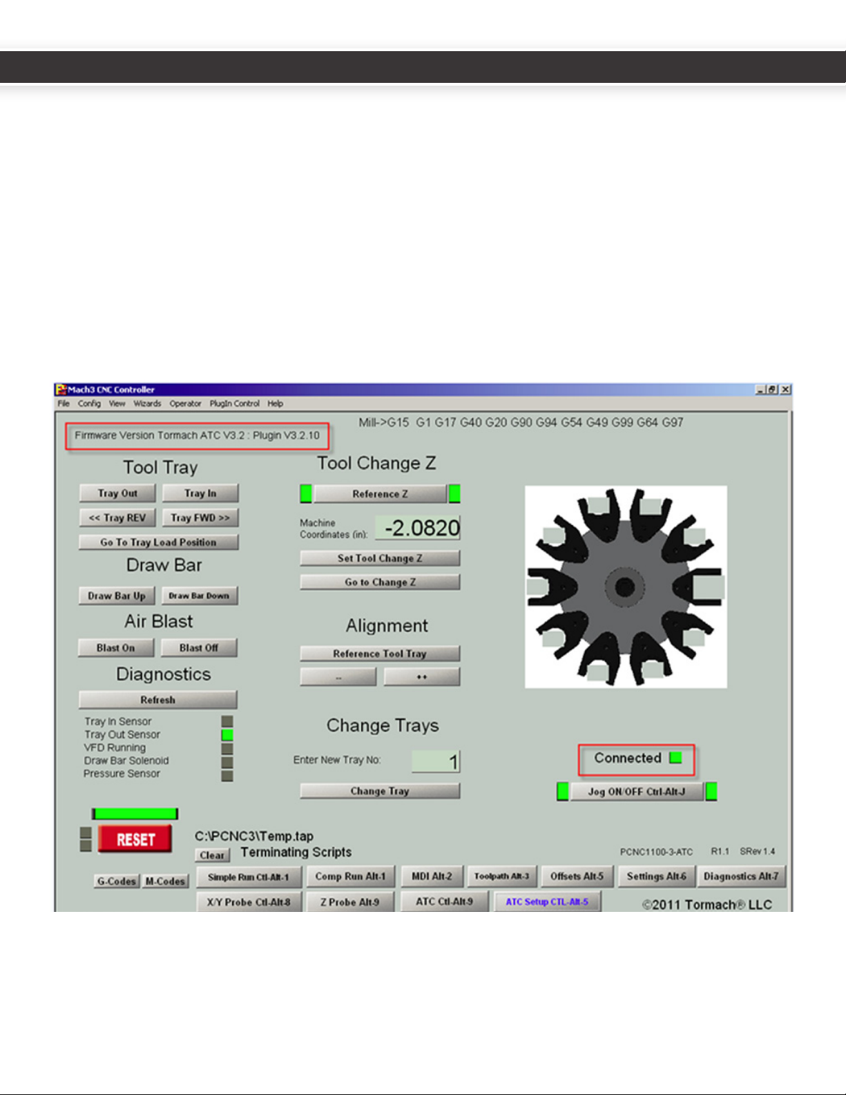
ClickontheATCSetupbuononthelowerporonofthescreen.Notethattheupperlecornerdisplaysthermware
andpluginversions.ThegreenCONNECTEDlightshouldbeglowingtoindicateUSBcommunicaonisestablished.This
veriesthesowareinstallaonandtheUSBconnecon.
14 15
UM10081_TTS_ATC_PCNC1100_1013A UM10081_TTS_ATC_PCNC1100_1013A

WiththeZaxisinthehomed(highest)posion,perform
thefollowingteststoverifytheoperaonofthetool
changer:
1. ApplyathinlmofwayoiltothelinearrailsoftheATC
slideassembly.Somechaerisexpectedunltheoil
haslubricatedthelinearbearings.
2. OntheATCSetupscreen,click“TrayIn”,“TrayOut”
buonstoverifythatthetrayairlinesarecorrectand
thatthemagnecaircylindersensorsareproperly
working.Message“ATCbuonexecuted”aereach
buonpressveriesoperaoncompleon.
3. Withthetrayinthe“in”posion,clickthe“Refresh”
buonunder“Diagnoscs”ontheATCSetupscreen.
VerifythattheTrayInSensorLEDisilluminatedwhen
the tray is in.
4. RepeatStep3forTrayOutposion.Youwillneedto
clickthe“Refresh”buontoreadthesensors.
• IfeithertheTrayInorTrayOutsensorfailstorespond
asexpected,refertothe“SensorIssue”seconin
Maintenance and Troubleshoong.
5. WiththetrayoutjogtheZaxisdownacoupleof
inches.
square tube mount.
Clickthe“GotoTrayLoadPosion”.Thisshouldmove
theZaxisupandbringthetrayin.
6. Clickthe“ReferenceToolTray”buonontheATC
Setupscreen-itshouldndandcenteronitshome
switch.Itwillturnunlitndsoneendofthesensor,
thenreverseandndtheotherendofthesensor,and
thencenterbetweenthesetwospots.
7. Testthedrawbarpendant.
8. OntheATCSetupscreen,clicktheDrawBarUp,Draw
BarDownbuons.Thedrawbarshouldoperate
accordingly.
9. ClickDrawBarDownbuonontheATCsetupscreen.
Itshouldreandlatch.Nowhitthetop(Lock)buon
onthependant.Itshouldunlatch.
10.ClickBlaston,BlastoontheATCSetupscreen.You
shouldheartheairstartandstopatthenozzlesinthe
tooltray.
11.Withatoolinthespindleandthetrayintheout
posion,startthespindleatlowspeedinmanual
mode.Clickthe“Refresh”buonontheATCSetup
screen,andverifythattheVFDRunningLEDis
illuminated.
12.Oponalpressuresensorvericaon:Ifyouhave
installedthepressuresensoraccessory(PN32329)
youmayverifythatthePressureSensorLEDonthe
ATCSetupscreenisilluminatedunderlowpressure
condionsanddarkundernormalpressurecondions.
Youwillhavetoclickthe“Refresh”buontoseethe
LEDchangecorrespondingtoachangeinstate.
6.1 Align Tool Tray and
Slots
Accuratealignmentofthetooltrayandslots,andthe
drawbarthrow,arethemostimportantfactorsinassur-
ingreliableandrepeatabletoolchangeroperaon.Take
yourme,andtakecaretodothisaccurately.Avideoof
thealignmentprocedurecanbewatchedonourwebsite:
hp://www.tormach.com/upgrades_s_atc.html
1. ItishelpfultogettheATCassemblyapproximately
levelusingabubblelevelbeforebeginningthe
alignmentprocedure.
16 17
UM10081_TTS_ATC_PCNC1100_1013A UM10081_TTS_ATC_PCNC1100_1013A
2. Makesurethespindleisiniallyempty.Thereshould
benotoolholderinthespindleatthispoint.
3. Clickthe“GoToTrayLoadPosion”buonontheATC
Setupscreen.TheZaxiswilljogupandthetraywill
actuatein,openingthetoolaccessdoor,andthedraw
barwillactuate.
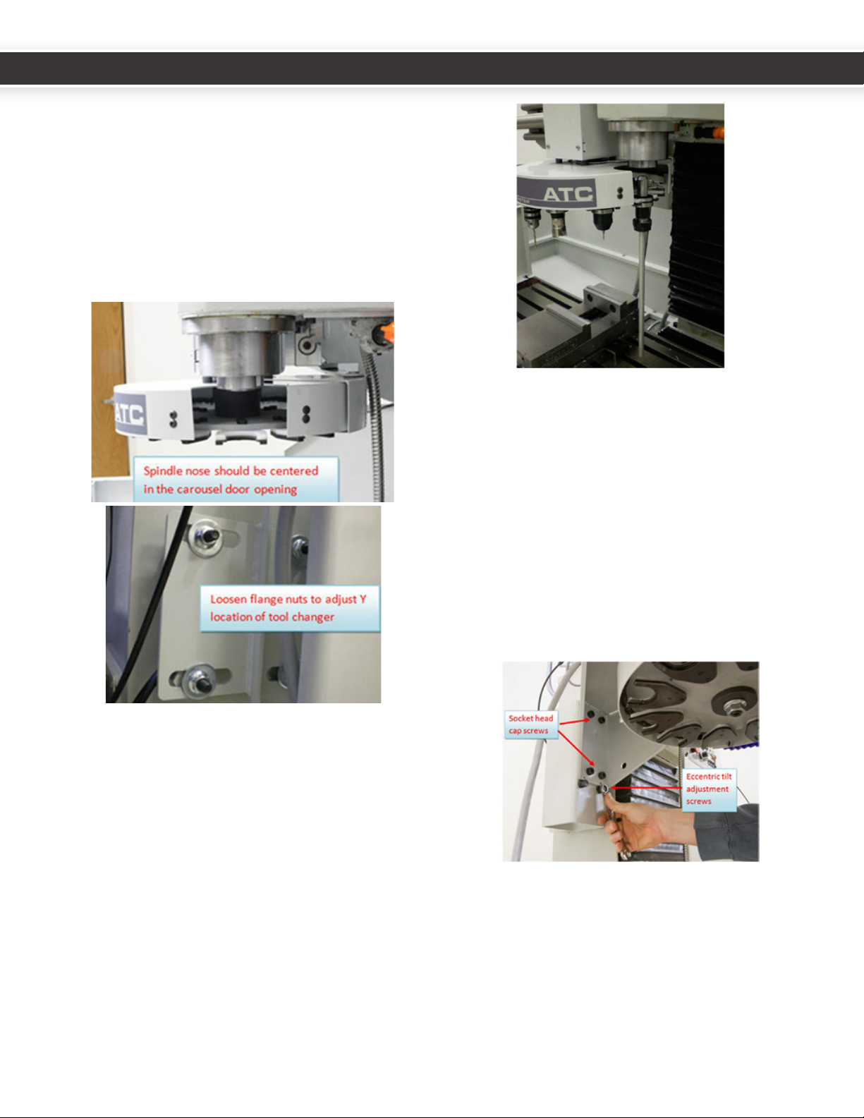
4. Verifythatthespindleisroughlyinthecenterofthe
carouseldooropening.Ifnecessary,movetheATC
forwardorbackwardbylooseningthefourangenuts
thatholdthesquaretubemounttothecolumn.
5. Insertalong(12-14”)dowelorpieceofroundstock
intoaTTStoolholder.Insertthetoolholderintothe
forkoftheexposedtrayslot.Usingothervercallines
(edgeofmilcolumn,Tslotsintable)sightalongthe
dowelandcheckwhetherthedowelandthespindle
axisareparallelinbothXandYplanes.
6. Ifthedowelandthespindleaxisarenotparallel,
adjusttheltoftheATCinbothXandYdirecons
unltheyare.
• TiltintheYdireconisfacilitatedbylooseningthe
angenutsthatholdthesquaretubemounttothe
column,thengentlytappingtheATCtrapezoidmount
with a mallet.
• TiltintheXdireconcanbeadjustedbyloosening
thesocketheadcapscrewsthatmounttheATCtothe
squaretube,thenturningtheeccentricadjustment
screws.ThisisbestdonewiththeATCinthe“Tray
In”posion,asthecenterofgravityoftheunitin
the“TrayIn”posionwillallowyoutouseboth
adjustmentscrewstolttheATC.
• Verifythatthetoolholdershankisparalleltothe
spindleaxisinbothXandYbyusinganangleblockor
1-2-3blockwithastraightedge:
16 17
UM10081_TTS_ATC_PCNC1100_1013A UM10081_TTS_ATC_PCNC1100_1013A
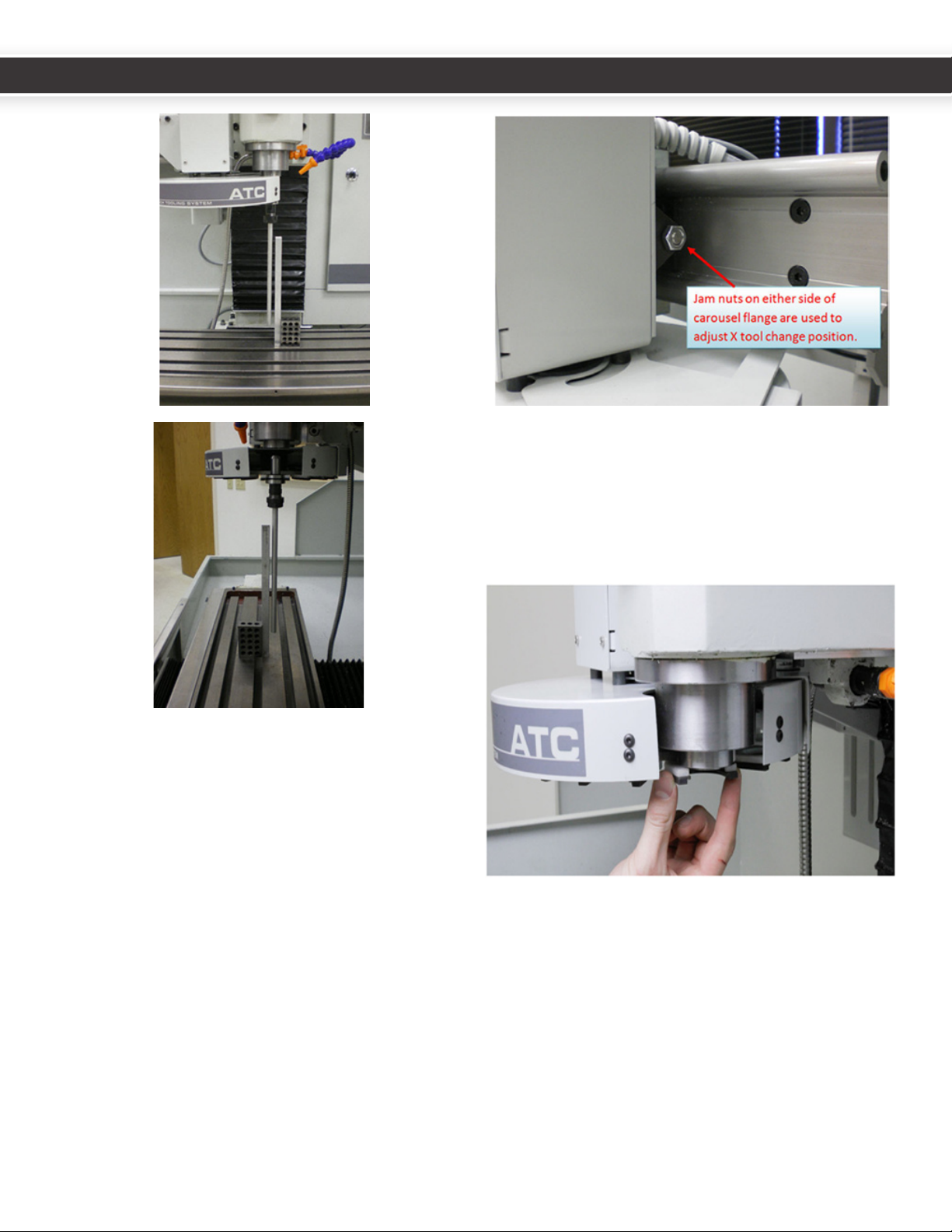
7. Onceyouaresasedthattheaxisofthedowelis
paralleltothespindleaxisinbothXandY,jogthe
spindledowntothetopoftheTormachtoolholder
shank.Donotgoallthewaydowntotheshoulderyet.
Verifybyeyethatitisroughlycenteredonthecollet
centeropening.
• Toadjustthealignmentofthetoolholdertothecollet
intheXdirecon,loosenthejamnutattheendofthe
traycylinderrodandmoveittoaroughlycentered
posion.Press“TrayIn”toverifytheadjustment.You
willlikelyhavetorepeatthisprocedureseveralmes
togetthelocaoncorrect.
• Toadjustthealignmentofthetoolholdertothecollet
intheYdirecon,usethe“--“or“++”-buonsonthe
ATCSetupscreenAlignmentsecon.Itisbesttowiggle
theforkwithyourthumbandindexngertofeelthe
extremesofthecarouselbacklashagainstthespindle
withyourngerstoseethatitisroughlycenteredle
andrightofforkwhilemakingthisadjustment.
18 19
UM10081_TTS_ATC_PCNC1100_1013A UM10081_TTS_ATC_PCNC1100_1013A
Other manuals for ATC
2
Table of contents
Other Tormach Industrial Equipment manuals

Tormach
Tormach PCNC 770 User manual

Tormach
Tormach Automatic Tool Changer User manual

Tormach
Tormach 770M User manual

Tormach
Tormach CNC Scanner User manual

Tormach
Tormach MICROARC 4 User manual

Tormach
Tormach 1100MX User manual

Tormach
Tormach 770MX User manual

Tormach
Tormach 51136 User manual

Tormach
Tormach 33318 Technical manual

Tormach
Tormach ATC User manual

Tormach
Tormach Slant-PRO 15L User manual

Tormach
Tormach PCNC 440 Technical manual

Tormach
Tormach 37335 User manual

Tormach
Tormach 24R User manual

Tormach
Tormach Slant-PRO 15L User manual

Tormach
Tormach 1100MX User manual

Tormach
Tormach 35550 Technical manual

Tormach
Tormach PCNC 1100 Deluxe Stand User manual


