Toro 39514 User manual

FormNo.3421-850RevC
24inStand-OnAerator
ModelNo.39514—SerialNo.400000000andUp
Registeratwww.Toro.com.
OriginalInstructions(EN)*3421-850*C

Important:Thisengineisnotequippedwitha
sparkarrestermufer.ItisaviolationofCalifornia
PublicResourceCodeSection4442tooperatethe
engineonanyforest-covered,brush-covered,or
grass-coveredland.Otherstatesorfederalareas
mayhavesimilarlaws.
Theenclosedengineowner'smanualissupplied
forinformationregardingtheUSEnvironmental
ProtectionAgency(EPA)andtheCaliforniaEmission
ControlRegulationofemissionsystems,maintenance,
andwarranty.Replacementsmaybeorderedthrough
theenginemanufacturer.
WARNING
CALIFORNIA
Proposition65Warning
Theengineexhaustfromthisproduct
containschemicalsknowntotheStateof
Californiatocausecancer,birthdefects,
orotherreproductiveharm.
Batteryposts,terminals,andrelated
accessoriescontainleadandlead
compounds,chemicalsknownto
theStateofCaliforniatocause
cancerandreproductiveharm.Wash
handsafterhandling.
Introduction
Thisaeratorisintendedforusebytrainedoperators
inresidentialandcommercialapplications.The
machineisprimarilydesignedforaeratingareasof
well-maintainedlawnsonresidentialgrounds,parks,
sportselds,andoncommercialgrounds.
Readthisinformationcarefullytolearnhowtooperate
andmaintainyourproductproperlyandtoavoid
injuryandproductdamage.Youareresponsiblefor
operatingtheproductproperlyandsafely.
YoumaycontactT orodirectlyatwww.T oro.com
forproductsafetyandoperationtrainingmaterials,
accessoryinformation,helpndingadealer,orto
registeryourproduct.
Wheneveryouneedservice,genuineT oroparts,or
additionalinformation,contactanAuthorizedService
DealerorToroCustomerServiceandhavethemodel
andserialnumbersofyourproductready.Figure1
identiesthelocationofthemodelandserialnumbers
ontheproduct.Writethenumbersinthespace
provided.
Important:Withyourmobiledevice,youcan
scantheQRcodeontheserialnumberdecal(if
equipped)toaccesswarranty,parts,andother
productinformation.
g246050
Figure1
1.Locationofthemodelandserialnumbers
ModelNo.
SerialNo.
Thismanualidentiespotentialhazardsandhas
safetymessagesidentiedbythesafety-alertsymbol
(Figure2),whichsignalsahazardthatmaycause
seriousinjuryordeathifyoudonotfollowthe
recommendedprecautions.
g000502
Figure2
1.Safety-alertsymbol
Thismanualuses2wordstohighlightinformation.
Importantcallsattentiontospecialmechanical
informationandNoteemphasizesgeneralinformation
worthyofspecialattention.
©2018—TheToro®Company
8111LyndaleAvenueSouth
Bloomington,MN554202
Contactusatwww.Toro.com.
PrintedintheUSA
AllRightsReserved

Contents
Safety.......................................................................4
GeneralSafety...................................................4
SafeOperatingPractices....................................4
AeratorSafety....................................................6
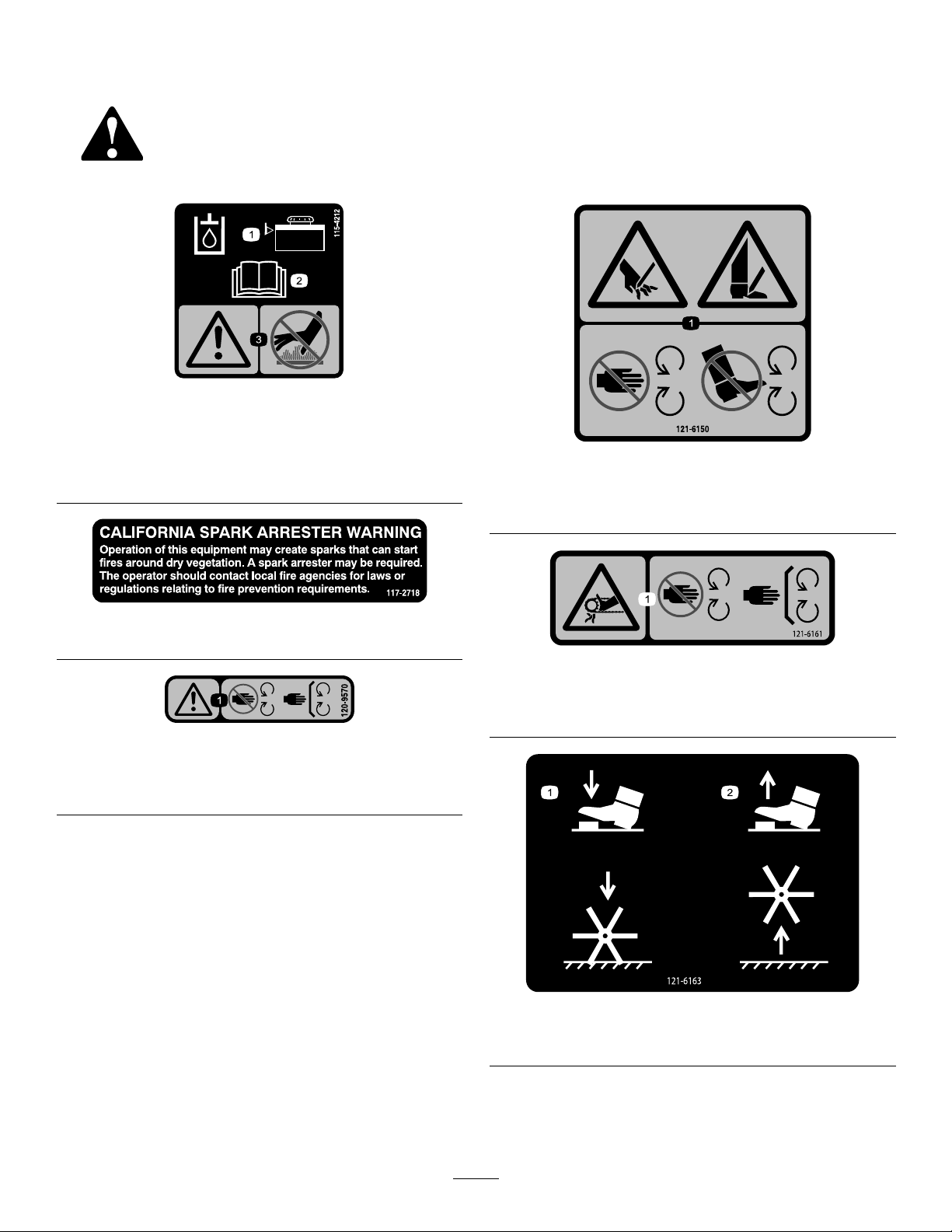
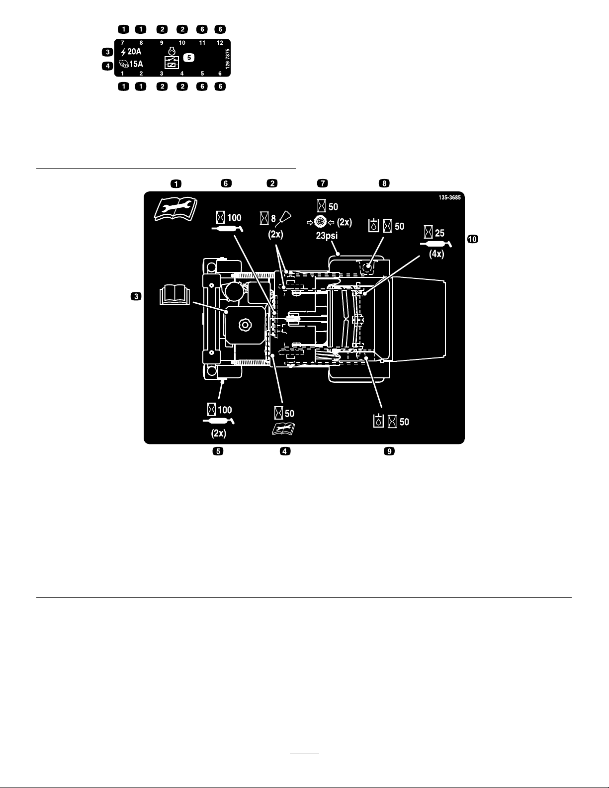
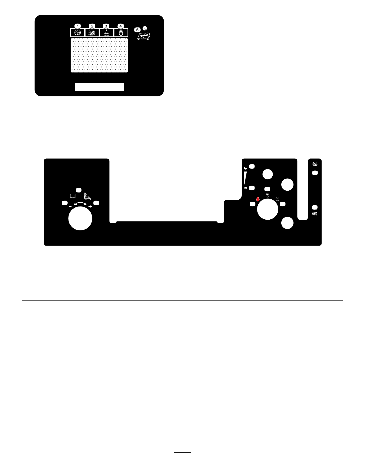
SafetyandInstructionalDecals..........................8
Setup......................................................................12
1CheckingTireAirPressure............................12
2ServicingtheEngineOil.................................12
3CheckingtheBatteryCharge.........................12
4CheckingtheTransmissionFluid...................13
5ChecktheAuxiliaryHydraulicFluid
Level.............................................................13
ProductOverview...................................................14
Controls...........................................................14
Specications..................................................21
Operation................................................................21
AddingFuel......................................................21
OpeningandClosingtheFuelShutoff
Valve.............................................................22
StartingtheEngine...........................................22
CheckingtheSafetyInterlock...........................23
LoweringtheTines...........................................23
ChangingtheTineDepthSetting......................23
Locking/UnlockingtheTineDepth
Setting...........................................................23
AdjustingtheOperatorWeightControl
Valve.............................................................23
RaisingtheTines..............................................24
ShuttingOfftheEngine.....................................24
DrivingtheMachine..........................................24
PositioningtheAir-CleanerCoverforColdor
WarmAirT emperature..................................25
AdjustingtheFrontReference/Speed
ControlBar....................................................26
LoadingtheMachine........................................26
TransportingtheMachine.................................26
Maintenance...........................................................28
MaintenanceSafetyInformation.......................28
RecommendedMaintenanceSchedule(s)...........30
Pre-MaintenanceProcedures..............................31
PreparingforMaintenance...............................31
Lubrication..........................................................31
LubricatingtheChains......................................31
LubricatingtheGreaseFittings.........................32
EngineMaintenance...........................................32
ServicingtheAirCleaner..................................32
ServicingtheEngineOil....................................33
ServicingtheSparkPlug...................................35
CheckingtheSparkArrester.............................36
ElectricalSystemMaintenance...........................36
JumpStartingtheMachine...............................36
ServicingtheBattery.........................................37
DriveSystemMaintenance..................................38
CheckingtheDriveTireAirPressure.................38
CheckingtheWheelHubBolts..........................38
CheckingtheT orqueoftheWheelLug
Nuts..............................................................38
CheckingtheConditionoftheChains...............39
CheckingtheSprocketCondition......................39
MaintainingtheChain.......................................39
CheckingtheT orqueoftheTransmission
OutputShaftNut...........................................39
AdjustingtheMotionControlLinkage................40
AdjustingtheMotionControlTracking...............40
CheckTransmissionMountBoltTorque............41
BrakeMaintenance.............................................41
AdjustingtheParkingBrake..............................41
BeltMaintenance................................................42
CheckingtheConditionandT ensionofthe
Belts..............................................................42
AdjustingtheAuxiliaryPumpDrive
Belt................................................................42
CheckingtheTransmissionDriveBelt
Tension.........................................................42
HydraulicSystemMaintenance...........................43
AuxiliaryHydraulicFluidSpecication..............43
CheckingtheAuxiliaryHydraulicFluid
Level.............................................................43
ChangingtheAuxiliaryHydraulicReservoir
FluidandFilter..............................................43
TransmissionFluidSpecication......................45
CheckingtheTransmissionFluidLevel.............45
ChangingtheHydraulicTransmissionFilters
andFluid.......................................................45
TineMaintenance.................................................47
CheckingtheTines...........................................47
AdjustingtheTineDriveChain..........................47
AdjustingtheReturn-to-UpSpring....................48
ChassisMaintenance...........................................48
CheckforLooseHardware...............................48
Cleaning..............................................................49
CleaningtheEngineandtheExhaust
SystemArea.................................................49
RemovingtheEngineShroudsandCleaning
theCoolingFins............................................49
CleaningtheDebrisfromtheMachine...............49
DisposingofWaste...........................................49
Storage...................................................................50
Troubleshooting......................................................51
3

Safety
GeneralSafety
Important:Theadditionofattachmentsmade
byothermanufacturersthatdonotmeetANSI
certicationmaycausenoncomplianceofthis
machine.
Thisproductiscapableofamputatinghandsandfeet.
Alwaysfollowallsafetyinstructionstoavoidserious
personalinjuryordeath.
•Donotputyourhandsorfeetnearmoving
componentsofthemachine.
•Theowner/usercanpreventandisresponsible
foraccidentsorinjuriesoccurringtopeople,or
damagetoproperty.
•Anyuseofthismachineotherthanaerating
turfgrasscouldprovedangeroustoyouand
bystanders.
•Stopthemachine,shutofftheengine,andremove
theignitionkeybeforeservicing,fueling,or
uncloggingthemachine.
Improperlyusingormaintainingthismachinecan
resultininjury.T oreducethepotentialforinjury,
complywiththesesafetyinstructionsandalways
payattentiontothesafety-alertsymbol,which
meansCaution,Warning,orDanger—personalsafety
instruction.Failuretocomplywiththeseinstructions
mayresultinpersonalinjuryordeath.
SafeOperatingPractices
ThefollowinginstructionsarefromANSIB71.4-2017.
Training
•Readandunderstandthecontentsofthis
Operator'sManualbeforestartingtheengine.
•Becomefamiliarwiththesafeoperationofthe
equipment,operatorcontrols,andsafetysigns.
•Alloperatorsandmechanicsshouldbetrained.
Theownerisresponsiblefortrainingtheusers.
•Neverletchildrenoruntrainedpeopleoperateor
servicetheequipment.Localregulationsmay
restricttheageoftheoperator.
•Theowner/usercanpreventandisresponsible
foraccidentsorinjuriesoccurringtohimselfor
herself,otherpeople,ordamagetoproperty.
Preparation
•Locateandmarkundergroundhazards.
•Evaluatetheterraintodeterminewhataccessories
andattachmentsareneededtoproperlyand
safelyperformthejob.Useonlyaccessoriesand
attachmentsapprovedbythemanufacturer.
•Wearappropriateclothing;includingsafety
glasses,longpants,substantial,slip-resistant
footwear,gloves,andhearingprotection.Tieback
longhair.Donotwearlooseclothingorloose
jewelry.
•Inspecttheareawhereyouwillusetheequipment
andremoveallobjectsfromtheareabeforeusing
themachine.
•Checkthattheoperator'spresencecontrols,safety
switches,andshieldsareattachedandfunctioning
properly.Donotoperatethemachineunlessthey
arefunctioningproperly.
4

SafeHandlingofFuels
•Toavoidpersonalinjuryorpropertydamage,use
extremecareinhandlingfuel.Fuelisextremely
ammableandthevaporsareexplosive.
•Extinguishallcigarettes,cigars,pipes,andother
sourcesofignition.
•Useonlyanapprovedfuelcontainer.
•Donotremovethefuelcaporaddfuelwiththe
enginerunning.
•Allowtheenginetocoolbeforefueling.
•Donotfuelordrainthemachineindoors.
•Donotstorethemachineorfuelcontainerwhere
thereisanopename,spark,orpilotlight,such
asonawaterheateroronotherappliances.
•Donotllcontainersinsideavehicle,onatruck,
oronatrailerbedwithaplasticliner.Alwaysplace
containersonthegroundawayfromyourvehicle
beforelling.
•Removeequipmentfromthetruckortrailerand
fuelitontheground.Ifthisisnotpossible,
thenaddfuelwithsuchequipmentasaportable
containerratherthanfromafuel-dispensernozzle.
•Keepthenozzleincontactwiththerimofthefuel
tankorcontaineropeningatalltimesuntilfueling
iscomplete.Donotuseanozzlelock-opendevice.
•Iffuelisspilledonclothing,changeyourclothing
immediately.
•Donotoverllthefueltank.Replacethefuelcap
andtightenitsecurely.
Operation
•Alwaysshutofftheengine,removethekey(if
equipped),waitforallmovingpartstostop,
andallowthemachinetocoolbeforeadjusting,
servicing,cleaning,orstoringthemachine.
•Donotoperatethemachinewhenthereistherisk
oflightning.
•Useyourfullattentionwhileoperatingthe
machine.Donotengageinanyactivitythat
causesdistractions;otherwise,injuryorproperty
damagemayoccur.
•Donotrunanengineinanenclosedarea.
•Donotsmokenearthemachinewhentheengine
isrunning.
•Operatethemachineonlyinwell-litareas,keeping
awayfromholesandhiddenhazards.
•Ensurethatalldrivesareinneutralandthatthe
parkingbrakeisengagedbeforestartingthe
engine.Starttheengineonlyfromtheoperator’s
position.
•Ensurethatyouhavegoodfootingwhileusingthis
machine,especiallywhenbackingup.Reduced
footingcouldcauseslipping.
•Slowdownanduseextracareonhillsides.Be
suretotravelsidetosideonhillsides.Turf
conditionscanaffectthestabilityofthemachine.
Usecautionwhileoperatingneardrop-offs.
•Slowdownandusecautionwhenmakingturns
andwhenchangingdirectionsonslopes.
•Donotoperatethemachinewithouttheshields
orotherguardssecurelyinplace.Ensurethatall
interlocksareattached,adjustedproperly,and
functioningproperly.
•Donotchangetheenginegovernorsettingor
overspeedtheengine.
•Stoponlevelground,disengagedrives,engage
theparkingbrake(ifprovided),shutofftheengine,
andremovethekeybeforeleavingtheoperator's
positionforanyreason.
•Stopequipment,shutofftheengine,removethe
key,andinspectthetinesafterstrikingobjectsorif
anabnormalvibrationoccurs.Makethenecessary
repairsbeforeresumingoperations.
•Keepyourhandsandfeetawayfromthetine
assembly.
•Lookbehindanddownbeforebackingupto
ensureaclearpath.
•Stopthemachineifanyoneentersthearea.Keep
petsandbystandersawayfromanoperating
machine.
•Slowdownandusecautionwhenmakingturns
andcrossingroadsandsidewalks.Fullyraisethe
tinesifyouarenotaerating.
•Donotoperatethemachinewhileill,tired,or
undertheinuenceofalcoholordrugs.
•Usecarewhenloadingorunloadingthemachine
intoorfromatrailerortruck.
•Usecarewhenapproachingblindcorners,shrubs,
trees,orotherobjectsthatmayobscurevision.
Hauling
•Usecarewhenloadingorunloadingthemachine
intoatraileroratruck.
•Itisrecommendedtouseonefullwidthrampthat
iswideenoughtoextendbeyondthereartires
insteadofindividualrampsforeachsideofthe
machine.
•Tiethemachinedownsecurelyusingstraps,
chains,cable,orropes.Bothfrontandrearstraps
shouldbedirecteddownandoutwardfromthe
machine.
MaintenanceandStorage
•Donotallowuntrainedpersonneltoservicethe
machine.
5

•Donottouchequipmentorattachmentpartsthat
maybehotfromoperation.Allowallofthepartsof
themachinetocoolbeforeattemptingtomaintain,
adjust,orservicethemachine.
•Keepyourhandsandfeetawayfrommoving
parts.Ifpossible,donotmakeadjustmentswith
theenginerunning.
•Disengagethedrives,raisethetines,engagethe
parkingbrake,shutofftheengine,andremove
thekeyordisconnectthespark-plugwire.Waitfor
allmovementtostopbeforeadjusting,cleaning,
orrepairing.
•Disconnectthebatteryorremovethespark-plug
wirebeforemakinganyrepairs.Disconnectthe
negativeterminalrstandthepositiveterminal
last.Connectthepositiverstandnegativelast.
•Usecarewhencheckingthetines.Wrapthetine(s)
orweargloves,andusecautionwhenservicing
them.Onlyreplacetines;donotstraightenorweld
them.
•Cleangrass,dirt,anddebrisfromthetines,drives,
mufers,andenginetohelppreventres.
•Cleanupoilorfuelspills.
•Parkmachineonlevel,hardground.Neverallow
untrainedpersonneltoservicethemachine.
•Usejackstandstosupportcomponentswhen
required.
•Carefullyreleasepressurefromcomponentswith
storedenergy.
•Donotstorefuelnearamesordrainthefuel
indoors.
•Alwaysshutofftheengine,removethekey(if
equipped),waitforallmovingpartstostop,
andallowthemachinetocoolbeforeadjusting,
servicing,cleaning,orstoringthemachine.
•Keepallpartsingoodworkingconditionandall
hardwaretightened.Replaceallwornordamaged
decals.
AeratorSafety
Thefollowinglistcontainssafetyinformationspecic
toToroproductsandothersafetyinformationyou
mustknow.
GeneralOperation
•Checkcarefullyforoverheadclearances(i.e.,
branches,doorways,electricalwires,etc.)before
operatingunderanyobjects,anddonotcontact
them.
•Usecautionwhenyouareridingontheplatform
anddrivingthemachineovercurbs,rocks,roots,
orotherobstructions.
•Donotjerkthecontrols;useasteadymotion.
•Donotcarrypassengers.
•Donotcarryequipmentonthemachine.
SlopeOperation
•Slopesareamajorfactorrelatedtolossofcontrol
androlloveraccidents,whichcanresultinsevere
injuryordeath.Theoperatorisresponsiblefor
safeslopeoperation.Operatingthemachineon
anysloperequiresextracaution.Beforeusingthe
machineonaslope,dothefollowing:
–Reviewandunderstandtheslopeinstructions
inthemanualandonthemachine.
–Evaluatethesiteconditionsofthedayto
determineiftheslopeissafeformachine
operation.Usecommonsenseandgood
judgmentwhenperformingthisevaluation.
Changesintheterrain,suchasmoisture,can
quicklyaffecttheoperationofthemachineon
aslope.
•Operateacrossslopes,neverupanddown.Avoid
operationonexcessivelysteeporwetslopes.
•Identifyhazardsatthebaseoftheslope.Do
notoperatethemachineneardrop-offs,ditches,
embankments,waterorotherhazards.The
machinecouldsuddenlyrolloverifawheelgoes
overtheedgeortheedgecollapses.Keepasafe
distance(twicethewidthofthemachine)between
themachineandanyhazard.Useawalkbehind
machineorahandheldtooltooperateinthese
areas.
6

g222486
Figure3
1.SafeZone:Usethemachinehere
2.DangerZone:Useawalkbehindmachineorahandheld
toolneardropoffs,ditches,embankments,waterorother
hazards.
3.Water
4.W=widthofthemachine
5.Keepasafedistance(twicethewidthofthemachine)
betweenthemachineandanyhazard.
•Avoidstarting,stoppingorturningthemachineon
slopes.Avoidmakingsuddenchangesinspeedor
direction;turnslowlyandgradually.
•Donotoperateamachineunderanyconditions
wheretraction,steeringorstabilityisinquestion.
Beawarethatoperatingthemachineonwet
grass,acrossslopesordownhillmaycausethe
machinetolosetraction.Lossoftractiontothe
drivewheelsmayresultinslidingandalossof
brakingandsteering.Themachinecanslideeven
ifthedrivewheelsarestopped.
•Removeormarkobstaclessuchasditches,holes,
ruts,bumps,rocksorotherhiddenhazards.Tall
grasscanhideobstacles.Uneventerraincould
overturnthemachine.
•Useextracarewhileoperatingwithaccessoriesor
attachments.Thesecanchangethestabilityof
themachineandcausealossofcontrol.Follow
directionsforcounterweights.
•Ifyoulosecontrolofthemachine,stepoffand
awayfromthedirectionoftravelofthemachine.
Service
•Toensureoptimumperformanceandcontinued
safetycerticationofthemachine,useonly
genuineT ororeplacementpartsandaccessories.
Replacementpartsandaccessoriesmadeby
othermanufacturerscouldbedangerous,and
suchusecouldvoidtheproductwarranty.
•Neverremoveortamperwithsafetydevices.
Checktheirproperoperationregularly.Neverdo
anythingtointerferewiththeintendedfunctionofa
safetydeviceortoreducetheprotectionprovided
byasafetydevice.
•Checkthebrakeoperationfrequently.Adjustand
servicethebrakesasrequired.
7

SafetyandInstructionalDecals
Safetydecalsandinstructionsareeasilyvisibletotheoperatorandarelocatednearanyarea
ofpotentialdanger.Replaceanydecalthatisdamagedormissing.
decal115-4212
115-4212
1.Hydraulic-uidlevel3.Warning—donottouchthe
hotsurface.
2.ReadtheOperator's
Manual.
decal117-2718
117-2718
decal120-9570
120-9570
1.Warning—stayawayfrommovingparts;keepallguards
andshieldsinplace.
decal121-6150
121-6150
1.Cuttinghazardofhandandfoot—stayawayfrommoving
parts.
decal121-6161
121-6161
1.Entanglementhazard,belt—stayawayfrommovingparts;
keepallguardsinplace.
decal121-6163
121-6163
1.Presstolowerthetines.2.Releasetoraisethetines.
8

decal126-7875
126-7875
1.Fuselocation4.Auxiliary(15A)
2.Relaylocation5.Startrelay
3.Main(20A)6.Notused
decal135-3685
135-3685
1.ReadandunderstandtheOperator’sManualbeforeservicing
thismachine.
6.Greasethebeltidlerpivotevery100hours
2.Cleanandoilthechainsandcheckthechaintensiontwice
every8hours
7.Checkthetirepressure-23psitwiceevery50hours
3.Seetheengineowner’smanualforservice8.Checkthehydraulicoilleveltwice(Useonlyrecommended
hydraulicuid)every50hours
4.Checktheauxiliarypumpdrivebelttensionevery50hours9.Checktheauxiliaryhydraulictank(UseonlyAW-32hydraulic
uid)every50hours
5.Greasethefrontcasterwheelbearingstwiceevery100hours10.Greasethetineshaftbearings4timesevery25hours
9

decal135-1854
135-1854
1.Parkingbrake4.Depthsetting—lock
2.Tineengagementlockout
switch
5.ReadtheOperator’s
Manualbeforeperforming
maintenance.
3.Tines—down
STOP
LB
KG
135-2013
2
1
3
4
5
6
7
8
9
10
decal135-2013-1
135-2013
1.Operatorweightadjustment5.Throttle—slow9.Parkingbrake—engage
2.Increase6.Engine—on10.Parkingbrake—release
3.Decrease7.Engine—start
4.Throttle—fast8.Engine—off
10

decal135-2014b
135-2014
1.Fast6.Wheelsandtinesrotatewhenmoving
backward
11.Thrownobjecthazard—pickupdebris
beforeoperatingthemachine.
2.Slow7.Warning—readtheOperator’sManual.12.Warning—shutofftheengine,engage
theparkingbreak,andremovethe
ignitionkeybeforeleavingthemachine.
3.Neutral8.Warning—keepbystandersasafe
distanceawayfromthemachine.
13.Tippinghazard–Donotoperatethe
machineneardrop-offs.
4.Reverse9.Warning—Cutting/dismemberment
hazardofhandorfoot;tines—stay
awayfrommovingparts;keepall
guardsinplace.
14.Tippinghazard–Donotturnsharply
whiletravelingfast;slowdownandturn
gradually.
5.Wheelsandtinesrotatewhenmoving
forward
10.Warning—Donotoperatethemachine
unlessyouaretrained.
15.Tippinghazard–Donotusesplitramps;
usefullwidthrampstoloadamachine
fortransport.
decal135-2016
135-2016
1.Electronictinedepth-decrease
2.Electronictinedepth-increase
3.Pressandhold1secondtoturnon—tineground
engagementfootswitchunlock
4.Pressandhold1secondtoturnoff—tineground
engagementfootswitchlock
decal135-3183
135-3183
1.Bypassleverpositionfor
pushingthemachine.
3.Bypassleverpositionfor
operatingthemachine.
2.Readtheinstructions
beforeservicingor
performingmaintenance.
11

Setup
LooseParts
Usethechartbelowtoverifythatallpartshavebeenshipped.
ProcedureDescriptionQty.Use
3Nopartsrequired–Checkthebatterycharge.
4Nopartsrequired–Checkingthetransmissionuid.
5Nopartsrequired–Checktheauxiliaryhydraulicuidlevel.
MediaandAdditionalParts
DescriptionQty.Use
Operator'sManual1Readbeforeoperatingthemachine.
Key2Startthemachine.
1
CheckingTireAirPressure
NoPartsRequired
Procedure
Checktheairpressureinthedrivetires,andadjust
thepressureasneeded;refertoCheckingtheDrive
TireAirPressure(page38).
Note:Youdonotadjustairpressureforthe
semi-pneumaticcastertires.
2
ServicingtheEngineOil
NoPartsRequired
Procedure
Theengineisshippedwithoil;checktheengine-oil
leveland,ifnecessary,addoiltothespeciedlevel;
refertoEngine-OilSpecication(page33)and
CheckingtheEngine-OilLevel(page33).
3
CheckingtheBattery
Charge
NoPartsRequired
Procedure
Themachineisshippedwithalled,lead-acidbattery,
Checkthechargeofthebatteryand,ifnecessary,
chargeit;refertoChargingtheBattery(page38).
12

4
CheckingtheTransmission
Fluid
NoPartsRequired
Procedure
Thetransmissionisshippedwithtransmissionuid.
Checkthetransmissionuidleveland,ifnecessary,
adduidtothespeciedlevel;refertoTransmission
FluidSpecication(page45)andCheckingthe
TransmissionFluidLevel(page45).
5
ChecktheAuxiliary
HydraulicFluidLevel
NoPartsRequired
Procedure
Theauxiliaryhydraulicreservoirisshippedwith
hydraulicuid.Checkthehydraulicreservoiruid
leveland,ifnecessary,adduidtothespeciedlevel;
refertoAuxiliaryHydraulicFluidSpecication(page
43)andCheckingtheAuxiliaryHydraulicFluidLevel
(page43).
13

ProductOverview
g232039
Figure4
1.Platform4.Motion-controllevers
2.Parkingbrakelever5.Fuelcap
3.Enginecontrols
Controls
g223341
Figure5
1.Tinegroundengagement
footswitch
7.Choke
2.Operatorweight
adjustmentcontrol
8.Rightmotion-controllever
3.Multi-functionswitch9.Hourmeter
4.Leftmotion-controllever10.Parking-brakehandle
5.Frontreferencebar11.Ignitionswitch
6.Throttle
Motion-ControlLevers
Themotion-controlleversarelocatedoneachsideof
thetopconsoleandcontroltheforwardandreverse
motionofthemachine.
Movetheleversforwardorbackwardtocontrolthe
drivewheelonthesamesideforwardorreverse
respectively.Thewheelspeedisproportionaltothe
amountyoumovethelever.
Important:Thetinesrotatewhenthe
motion-controlleversaremovedoutofthe
NEUTRALposition.
14

g223330
Figure6
1.Leftmotion-controllever5.Forward
2.Rightmotion-controllever6.Neutral
3.Frontreferencebar7.Reverse
4.Frontofmachine8.Rearreferencebar
ThrottleLever
Thethrottlelever(Figure5)islocatedonthecontrol
console(redlever).
Usethethrottlelevertocontrolenginespeed.Move
thethrottleleverforwardtoincreaseenginespeed;
movingthethrottleleverrearwardtodecreasethe
enginespeed.
Note:Movethethrottleleverforwardintothedetent
forfullthrottle.
ChokeControl
Thechokecontrol(Figure5)islocatedonthecontrol
console.
Usethechokecontroltoaidinstartingacoldengine.
PulloutthechokecontroltosetthechoketotheON
position;pressinthechokelevertoreducethechoke.
Note:Pulloutthechokecontroltosetthechoketo
theONposition.
Note:Donotrunawarmenginewiththechokein
theONposition.
IgnitionSwitch
TheIgnitionswitchislocatedontherightsideofthe
controlconsole(Figure5).
UsetheIgnitionkeytostartandshutofftheengine.
Theswitchhas3positions:OFF,ON,andSTART
(Figure7).
g008610
Figure7
1.OFF3.START
2.ON
Parking-BrakeHandle
Theparking-brakehandleislocatedonthecontrol
console,totherightofthekeyswitch(Figure5).
Note:Thebrakehandleengagesaparkingbrakein
eachofthetransmissions.
•Toengagetheparkingbrake,pullthehandleback
towardyou.
•Toreleasetheparkingbrake,pushthehandleall
thewayforwardawayfromyou.
Whenparkingonaslope,chockorblockthewheels
inadditiontoengagingtheparkingbrake.Tiedown
themachineandengagetheparkingbrakewhen
transportingthemachine.
Fuel-ShutoffLever
Locatedundertheaircleaneronthefrontrightside.
Thefuel-shutoffleverisusedtoshutoffthefuelwhen
youwillnotusethemachineforafewdays,whileyou
aretransportingthemachinetoandfromthejobsite,
andwhenthemachineisparkedinsideabuilding.
Rotatethehandlecounterclockwisetoopen;rotate
clockwiseto90°toclose.
Drive-WheelReleaseValves
WARNING
Handsmaybecomeentangledintherotating
drivecomponentsbetweentheengineand
transaxles,whichcouldresultinserious
injuryordeath.
Shutofftheengine,removethekey,andallow
allthemovingpartstostopbeforeaccessing
thedrive-wheelreleasevalves.
15

WARNING
Theengineandhydraulicdriveunitscan
becomeveryhot.Touchingahotengineor
hydraulicdriveunitscancausesevereburns.
Allowtheengineandhydraulicdriveunits
tocoolcompletelybeforeaccessingthe
drive-wheelreleasevalves.
Locatedontheleftandrightsidesabovethe
transaxles.
Duringnormaloperatingconditions,thewasheron
theleverispositionedoutsidetheslots.Ifyoumust
pushthemachinebyhand,thevalvesmustbeinthe
releasedposition(seeFigure8).
g211754
Figure8
1.Leverpositionfor
operatingthemachine
3.Leverpositiontopushthe
machine
2.Washeroutsideofslot4.Washerinsideslot
Toreleasethedrivewheels,movethelevertothe
largeropeningoftheslot,pushitinuntilthewasher
isinsidetheframe,thenmovetheleverbacktothe
narrowportionoftheslot.Repeatthisoneachside
ofthemachine.
Releasetheparkingbrake.Youcannowpushthe
machinebyhand.
Donottowthemachine.
Toresetthedrivesystembacktotheoperating
position,movethelevertothelargeropeningofthe
slot,pulloutwarduntilthewasherisoutsideofthe
frame,thenmovetheleverbacktothenarrowportion
oftheslotoneachsideofthemachine.
OperatorWeightAdjustment
Control
Theoperatorweightadjustmentvalveislocatedatthe
leftsideofthecontrolconsole(Figure9).
g249578
Figure9
1.Operatorweightadjustmentcontrol
Usetheoperatorweightadjustmentvalvetohelp
compensatefortheweightoftheoperatorsothatthe
machineachievesthecorrectaeratingpressure,plug
length,andtohelpmaximizelateralmachinestability.
Note:Eachoperatormustadjustthesystempressure
sothatthedrivetireslightlytouchtheground.
Important:Keepthedrivetiresonthegroundat
alltimestomaximizelateralmachinestability.
Tine-PressureControl
Thetine-pressurecontrolislocatedontheleftsideof
thecontrolconsole(Figure5).
Usethetine-pressurecontroltoadjustthedownward
pressureonthetinesandcoredepth.Rotatethe
controlcounterclockwisetodecreasethepressure
andthelengthoftheaerationplug;rotateitclockwise
toincreasethepressureandincreasethelengthof
theaerationplug.
TineGroundEngagementFoot
Switch
Keepyourhandsandfeetawayfromthe
tines.Ensurethatthetinesareaisclearofany
obstructionsbeforeloweringit.
Theswitchislocatedontheoperatorplatform.
Tolowerthetinesintotheground,standonthe
tinegroundengagementswitch.Toraisethetines,
removeyourfootfromtheswitch.
Thisswitchcanbelockedout(disabled)withthe
multi-functionswitch.
16

•Tapandholdthebottomoftheswitchtooverride
andlockout(disable)thefootswitch.TheLED
illuminatesinthehourmeter/tineengagement
display.Usethisfeaturewhentransportingthe
aerator.
•Tounlock,tapandholdthetopofthemulti-function
switchuntiltheLEDlightdisappears.
Note:Thelockoutfeatureisengagedeachtimethe
engineisswitchedoff.
Multi-FunctionSwitch
Themulti-functionswitchislocatedtotheleftofthe
hourmeter/tineengagementdisplay.
Thisswitchallowstheoperatortodothefollowing:
•increaseordecreasethedepthofaerationplug
•lockorunlockthetinedepthsetting
•resetmaintenanceservicereminderscreens
SmartController/ElectronicDepth
Control
HourMeter/TineEngagementDisplay
Locatedtotheleftoftheignitionswitchonthecontrol
console.
•Thehourmetermonitorsanddisplaysengine
hours.
g211730
Figure10
HourMeterDisplay
1.LCDIndicators/Informationscreen
2.Hourdisplay
3.LEDstatuslight
Hoursaredisplayedwhenthekeyisofforwhen
themachineisrunning.Hoursarenotdisplayed
whenthemachineisaerating.
Note:TheLCDindicatorappearsintheparking
brakesettingwhenitmeetsthesafetostartmode
(parkingbrakeengaged).
•Thetineengagementdisplaymonitorsand
displaystheelectronictinedepthsetting.
g211731
Figure11
TineEngagementDisplay
1.LCDIndicators/Informationscreen
2.Tinedepthstatusbar
3.Tinedepthsettingindicator
4.LEDstatuslight
Therearetwowaystoactivatethedisplay.
1.T apthemulti-functionswitcheitherupordown
todisplaythetineengagementmeter.
2.Steponthetinegroundengagementfootswitch.
Ahighernumberonthestatusbarincreasesthe
lengthoftheaerationplugandalowernumber
decreasesit.
Note:Ifthepluglengthisnotthedesiredlength,you
mayneedtoadjustthemachinetoaccommodate
foryourweight;refertotheAdjustingtheOperator
WeightControlValve(page23).
LEDStatusLights
Locatedontherightsideofthehourmeter/tine
engagementdisplay.
TheLEDismulti-coloredtoindicatethesystemstatus
andislocatedontherightsideofthepanel.
•SolidGreen—indicatesnormaloperatingactivity
•BlinkingRed—indicatesthatafaultisactive
•SolidRed—indicatesthatmaintenanceis
required
17

ScreenIcons
Theinformationscreenusesthefollowingicons:
AeratingHoursParkingbrake
BatteryVoltageEngineOilMaintenance
HourMeter
TransmissionOil
Maintenance
VoltageErrorValveSolenoidError
ValveSolenoidConnection
Error
Start-upScreens
WhenthekeyisswitchedfromOFFtoRUNposition,
thefollowingscreensdisplayfor2seconds.TheLED
statuslightchangesfromredtoorangetogreen.
Therstscreendisplaysthermwareversion.
g212116
Figure12
Thesecondscreendisplaystheaerationhourstothe
tenthofanhour.
g212114
Figure13
Thethirdscreendisplaysthebatteryvoltagetothe
tenthofavolt.
g212115
Figure14
Thefourthscreendisplaysthehoursuntiltheengine
oilmaintenanceisrequired.Iftheserviceisnot
performed,thetimeisrecordedasnegativehoursto
indicatethenumberofhourspastduefortheservice
(upto-500hours).
18

g212117
Figure15
Thenalscreendisplayedisthehoursuntil
transmissionoilmaintenanceisrequired.Ifthe
serviceisnotperformed,thetimeisrecordedas
negativehourstoindicatethenumberofhourspast
duefortheservice(upto-500hours).
g212118
Figure16
MaintenanceReminderScreens
Thehourmeterdisplaysthenumberofengine
hoursuntileithertheengineoilortransmissionoil
maintenanceisdue.Thereminderashesandthe
LEDdisplaysasteadyredlight.
Analertoccurswhenthehourcounterreacheszero.
Iftheserviceisnotperformed,thetimeisrecorded
asnegativehourstoindicatethenumberofhours
pastduefortheservice(upto-500hours)(reference
Figure17andFigure18).Thehourmeterswitches
betweenthedefaultscreenandtheactivealert
screen.Ifmorethan1alertisactive,thedisplay
cyclesbetweenthealertsintheorderthatthey
occurredbeforecyclingbacktothedefaultscreen.
Thealertsonlydisplaywhenthedefaultscreenhas
beenactivefor2seconds;howeverifthekeyismoved
totheSTARTposition,thealertsoccurimmediately.
Whenthemachineisaerating,thealertscreendoes
notdisplaybuttheLEDstatuslightremainsasteady
red.
Therearetwomaintenancereminders:
1.ServiceEngine
Theengine-oilserviceremindercountsdown
fromtheinitialbreak-inserviceintervalof5
enginehoursandthencountsdownfrom100
hoursforeachserviceintervalthereafter.
g030960
Figure17
2.ServiceTransmission
Thetransmissionoilmaintenancereminder
countsdownfromtheinitialbreak-inservice
intervalof250enginehoursandthencounts
downfrom500hoursforeachserviceinterval
thereafter.
g030965
Figure18
Youcanresetmaintenanceremindersmanually.
•Youcanentertheengineservicereminderreset
modebycyclingthekeyswitchbetweentheRUN
positionandtheOFFposition4timeswithin8
secondswiththeparkingbrakeengaged.
WhentheServiceEnginescreendisplays
andashes,youcanresettheengine-oil
maintenancereminderbypressingthedownon
themulti-functionswitch.Oncethereminder
resets,thescreenexitstheServiceEngine
screenandreturnstothedefaultscreen.
YoucanexittheServiceEnginescreenatany
timebyturningthekeytoeithertheOFForthe
STARTposition.
•Youcanenterthetransmission-oilmaintenance
reminderresetmodebycyclingthekeyswitch
fromtheRUNpositiontotheOFFpositionandback
totheRUNposition,6timeswithin8seconds,with
theparkingbrakeengaged.
WhentheServiceTransmissionscreendisplays
andashes,youcanresetthetransmission-oil
19

maintenancereminderbypressingdownonthe
multi-functionswitch.
YoucanexittheServiceEnginescreenatany
timebyturningthekeytoeithertheOFForthe
STARTposition.
AlertsandErrorMessages
Thesystemiscapableofdisplayingthefollowing
errors:
•VoltageError
ThisoccurswhentheKey-Runvoltageislessthan
12.3orgreaterthan16,avoltageerrorashes.
TheLEDashesaredlight.
g030966
Figure19
•ValveSolenoidOpenError
Ifeither1ofthe2valvesolenoidsdisconnect,the
number6displaysinthelowerleftcornerofthe
screen.TheLEDashesaredlight.
g030971
Figure20
1.Number6displays
•ValveSolenoidOvercurrentError
Ifanovercurrenteventoccurs,thenumber2
displaysinthelowerleftcornerofthescreen.
Checkthevalvesolenoidandinspectitfordamage
andwear.TheLEDashesaredlight.
g030972
Figure21
1.Number2displays
•ValveSolenoidConnectionError
ThesystemdisplaystheValveSolenoid
ConnectionErroralertandtheLEDashesred
whenthesystemdetectsanerror.Ifthevalve
solenoidsareconnectedincorrectly(i.e.the
connectorforthereliefvalveisconnectedtothe
othervalvesolenoid)thetinesdonotoperateuntil
thefaultiscorrected.
g030977
Figure22
20
Other manuals for 39514
1
Table of contents
Other Toro Lawn And Garden Equipment manuals

Toro
Toro Greensmaster 3000 Series User manual

Toro
Toro Groundsmaster 3320 Series User manual

Toro
Toro 686 User manual

Toro
Toro 23515 User manual

Toro
Toro 135-7423 User manual

Toro
Toro 22615 User manual

Toro
Toro 39519 User manual

Toro
Toro 03662 User manual

Toro
Toro 41323 User manual

Toro
Toro 30392 User manual
Popular Lawn And Garden Equipment manuals by other brands

DURABLE
DURABLE GreenDed quick start guide

SNOWJOE
SNOWJOE SunJoe 24V-SS12-XR Operator's manual

AL-KO
AL-KO COMBI-CARE 38 P comfort manual

Hyundai power products
Hyundai power products FWGE1200-H-1 Original instructions

Gardena
Gardena 1197 operating instructions

RedMax
RedMax EXtreme EX-LRT Owner's/operator's manual