manuals.online logo
Brands
  1. Home
  2. •
  3. Brands
  4. •
  5. Toro
  6. •
  7. Lawn And Garden Equipment
  8. •
  9. Toro 03662 User manual

Toro 03662 User manual

Other Toro Lawn And Garden Equipment manuals
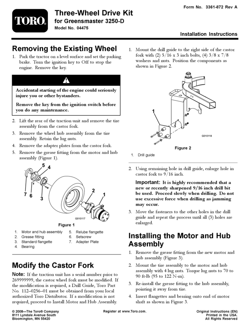
Toro 07511AA Quick start guide

Toro

Toro 07511AA Quick start guide

Toro 66100 Series User manual

Toro

Toro 66100 Series User manual

Toro Bullseye QuickGroom 700 User manual

Toro

Toro Bullseye QuickGroom 700 User manual

Toro 23702 User manual

Toro

Toro 23702 User manual

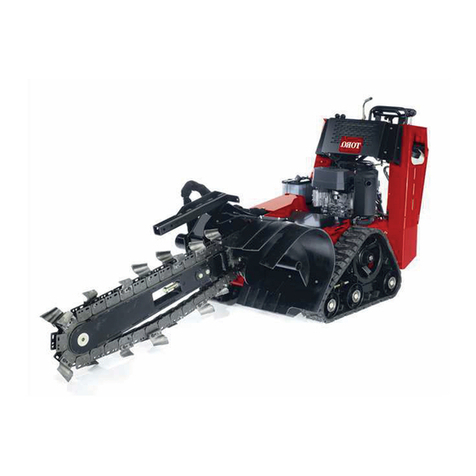
Toro 04476 User manual

Toro

Toro 04476 User manual

Toro Sand Pro 3040 User manual

Toro

Toro Sand Pro 3040 User manual

Toro Versa Vac 07082 User manual

Toro

Toro Versa Vac 07082 User manual

Toro 38365 User manual

Toro

Toro 38365 User manual

Toro 686 User manual

Toro

Toro 686 User manual

Toro Flex-Force Power System 88714 User manual

Toro

Toro Flex-Force Power System 88714 User manual

Toro T7 Series User manual

Toro

Toro T7 Series User manual

Toro T7 Series User manual

Toro

Toro T7 Series User manual

Toro 119-4121 User manual

Toro

Toro 119-4121 User manual

Toro 117-9170 User manual

Toro

Toro 117-9170 User manual

Toro 30639 User manual

Toro

Toro 30639 User manual

Toro ProCore 864 User manual

Toro

Toro ProCore 864 User manual

Toro TimeMaster 21199 User manual

Toro

Toro TimeMaster 21199 User manual

Toro 23210 User manual

Toro

Toro 23210 User manual

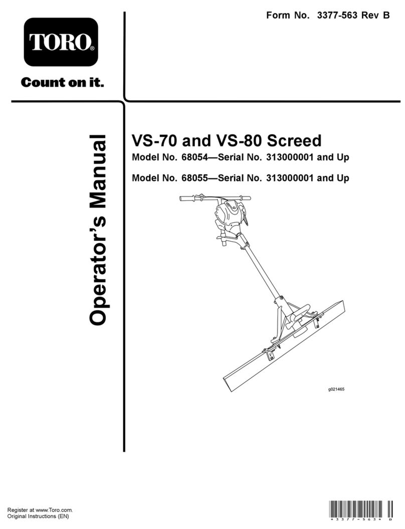
Toro VS-70 User manual

Toro

Toro VS-70 User manual

Toro Sand Pro 2040Z User manual

Toro

Toro Sand Pro 2040Z User manual

Toro Flex-Force Power System 51810T User manual

Toro

Toro Flex-Force Power System 51810T User manual

Toro HydroJect 3010 User manual

Toro

Toro HydroJect 3010 User manual

Toro 108-3654 User manual

Toro

Toro 108-3654 User manual

Toro ProCore 648 User manual

Toro

Toro ProCore 648 User manual

Popular Lawn And Garden Equipment manuals by other brands

Sunforce SOLAR user manual

Sunforce

Sunforce SOLAR user manual

GARDEN OF EDEN 55627 user manual

GARDEN OF EDEN

GARDEN OF EDEN 55627 user manual

Goizper Group MATABI POLMINOR instruction manual

Goizper Group

Goizper Group MATABI POLMINOR instruction manual

Rain Bird 11000 Series Operation & maintenance manual

Rain Bird

Rain Bird 11000 Series Operation & maintenance manual

Cub Cadet BB 230 brochure

Cub Cadet

Cub Cadet BB 230 brochure

EXTOL PREMIUM 8891590 Translation of the original user manual

EXTOL PREMIUM

EXTOL PREMIUM 8891590 Translation of the original user manual

Snapper 690179 installation instructions

Snapper

Snapper 690179 installation instructions

Exmark SAR481KA30 Operator's manual

Exmark

Exmark SAR481KA30 Operator's manual

Yazoo/Kees Z12 Operator's manual

Yazoo/Kees

Yazoo/Kees Z12 Operator's manual

Makita EM408MP Original instruction manual

Makita

Makita EM408MP Original instruction manual

Exmark Quest Bagger Setup instructions

Exmark

Exmark Quest Bagger Setup instructions

Manitou Systems AS960 Operator's manual

Manitou Systems

Manitou Systems AS960 Operator's manual

Vertex 1/3 HP Maintenance instructions

Vertex

Vertex 1/3 HP Maintenance instructions

GHE AeroFlo 80 manual

GHE

GHE AeroFlo 80 manual

Land Pride Post Hole Diggers HD25 Operator's manual

Land Pride

Land Pride Post Hole Diggers HD25 Operator's manual

Yazoo/Kees Z9 Commercial Collection System Z9A Operator's & parts manual

Yazoo/Kees

Yazoo/Kees Z9 Commercial Collection System Z9A Operator's & parts manual

Premier designs WindGarden 26829 Assembly instructions

Premier designs

Premier designs WindGarden 26829 Assembly instructions

Snapper 1691351 installation instructions

Snapper

Snapper 1691351 installation instructions

manuals.online logo
manuals.online logoBrands
  • About & Mission
  • Contact us
  • Privacy Policy
  • Terms and Conditions

Copyright 2025 Manuals.Online. All Rights Reserved.

FormNo.3386-464RevB
GrassBasketKit
ForReelmaster®5010SeriesCuttingUnitswith5inand7inReels
ModelNo.03662
InstallationInstructions
Installation
LooseParts
Usethechartbelowtoverifythatallpartshavebeenshipped.
ProcedureDescriptionQty.Use
Cylindercollar4
Bolt4
Flangedlocknut8
Spacer2
Stopbracket2
1
Carriagebolt4
Installtherearliftcylinderlimitkit
(orderedseparately).
Basketguide1
Basketbracket1
Rollpin1
Washer1
Left-handtorsion-spring(gold)1
Right-handtorsion-spring(black)1
Basketcollar1
Flatwasher(0.344x0.875)2
Bolt(5/16x1–1/4inch)1
Bolt(5/16x1/2inch)1
2
Plasticwasher1
Installthebasketguidesandbrackets.
Cut-offbar1
Bolt(1/4x1–3/4inches)4
3Locknut(1/4inch)4
Installthecut-offbar.
4Nopartsrequired–Removethe4grassdeectors.
5Flangedlocknut2Removethesupporttube(for5–inch
diameterreelsonly).
6Basketassembly1Mountthebasketassemblytothe
cuttingunit.
7Nopartsrequired–Adjustthebasketposition.
Important:Togainadditionalclearancefortherearbasketswhenraisingthecuttingunits,installtheRearLift
CylinderLimitKit.
©2015—TheToro®Company
8111LyndaleAvenueSouth
Bloomington,MN55420
Registeratwww.T oro.com.OriginalInstructions(EN)
PrintedintheUSA
AllRightsReserved*3386-464*B
1
InstallingtheRearLiftCylinder
LimitKit(OrderedSeparately)
Partsneededforthisprocedure:
4Cylindercollar
4Bolt
8Flangedlocknut
2Spacer
2Stopbracket
4Carriagebolt
For7-inchDiameterReels
Note:TheRearLiftCylinderLimitKit(Toropartno.
110–9604)isorderedseparately.ContactanAuthorizedToro
Dealertoorderthekit.
1.Positionthetractionunitonalevelsurface,lowerthe
liftarms/cuttingunits,andstopthemachine.Remove
thekeyfromtheignitionswitchtopreventaccidental
starting.
Important:TheRearLiftCylinderLimitKitis
onlytobemountedonthe#2and#3(rear)lift
armcylinders.
2.Installthecylindercollarstotheextendedcylinderrod
with2boltsand2angelocknuts(Figure1).Make
surethecylindercollarstoverthetopofthecylinder.
3.Looselyinstallthestopbrackettothedeectorbracket
with2carriageboltsand2locknuts(Figure1).
4.Movethestopbrackettothehighestpositiononthe
bracketandtightentheangelocknuts(Figure1).
For5-inchDiameterReels
Note:TheRearLiftCylinderLimitKit(Toropartno.
110–9604)isorderedseparately.ContactanAuthorizedToro
Dealertoorderthekit.
1.Positionthetractionunitonalevelsurface,lowerthe
liftarms/cuttingunits,andstopthemachine.Remove
thekeyfromtheignitionswitchtopreventaccidental
starting.
Important:TheRearLiftCylinderLimitKitis
onlytobemountedonthe#2and#3(rear)lift
armcylinders.
2.Installthecylindercollarsandthespacertothe
extendedcylinderrodwith2boltsand2ange
locknuts(Figure1).Makesurethecylindercollarst
overthetopofthecylinderandthespacerisushwith
thecylinderend.
3.Looselyinstallthestopbrackettothedeectorbracket
with2carriageboltsand2locknuts(Figure1).
4.Movethestopbrackettothelowestpositiononthe
bracketandtightentheangelocknuts(Figure1).
Figure1
1.Cylindercollar5.Stopbracket
2.Spacer6.Deectorbracket
3.Bolt7.Carriagebolt
4.Flangelocknut
2
2
InstallingtheBasketGuides
andBrackets
Partsneededforthisprocedure:
1Basketguide
1Basketbracket
1Rollpin
1Washer
1Left-handtorsion-spring(gold)
1Right-handtorsion-spring(black)
1Basketcollar
2Flatwasher(0.344x0.875)
1Bolt(5/16x1–1/4inch)
1Bolt(5/16x1/2inch)
1Plasticwasher
Procedure
1.Removethecuttingunitsfromthecartons.Assemble
andadjustthemaccordingtotheOperator’sManualfor
thecuttingunit.
2.UseFigure2todeterminethelocationswherethe
basketguidesorbasketbracketsmustbemountedto
thecutting-unitcarrier-frames.
Figure2
1.Centerbasket5.Right,frontbasket
2.Left,rearbasket6.Basketguide
3.Right,rearbasket7.Basketbracket
4.Left,frontbasket
3.Mountabasketguidetotheappropriatesideofeach
cuttingunitcarrierframe(Figure2)withabolt(5/16x
1/2inch)andatwasher(0.344x0.875).Positionthe
componentsasshowninFigure3.
Figure3
1.Carrierframe3.Flatwasher(0.344x
0.875)
2.Basketguide4.Bolt(5/16x1/2inch)
4.Installarollpinintothelowerholeintheappropriate
sideofeachcuttingunitcarrierframe(Figure4).The
endoftherollpinshouldbeushwiththeinnerside
ofthecarrierframe.
Figure4
1.Carrierframe5.Torsionspring(lefthand
shown)
2.Rollpin6.Basketcollar
3.Plasticwasher7.Flatwasher(0.344x
0.875)
4.Basketbracket8.Bolt(5/16x1–1/4inch)
5.Onthesamesideofthecarrierframethattherollpin
isinstalled,mountaplasticwasher,basketbracket,
torsionspring,basketcollar,atwasher(0.344x0.875)
andbolt(5/16x1-1/4inches)(Figure4).
Note:Theplasticwasher,basketbracket,andtorsion
springtontothebasketcollar.
Thegoldtorsionspringisfortheleft-handsideofthe
carrierframeandtheblackspringisfortheright-hand
sideofthecarrierframe.Thelongerlegofthespringis
tobepositionedaroundthefrontofthecarrierframe
3
andtheshorter,rearlegofthespringistobeinserted
intotheholeinthebasketbracket.
6.Checkifthebracketbasketrotatesfreely.
Important:Theplasticwashermustbeinstalled
ontothebasketcollartopreventbinding.
3
InstallingtheCut-offBar
Partsneededforthisprocedure:
1Cut-offbar
4Bolt(1/4x1–3/4inches)
4Locknut(1/4inch)
Procedure
1.Looselymountthecut-offbartothecuttingunitframe
with4bolts(1/4x1–3/4inches)and4locknuts(1/4
inch)(Figure5).
Figure5
1.Cut-offbar4.Bolt(1/4x1–3/4inches)
2.Grassshield5.Locknut(1/4inch)
3.Deector
2.Inserta0.060feelergaugebetweenthetopofthereel
andthebottomofthecut-offbartocheckclearance.
Makesurethebarandreelareequaldistanceapart
acrossthefulllengthofthereel.
Note:Thecut-offbarmustnotcontactthereelduring
operation.
3.Tightentheboltsandlocknuts(Figure5).
4
Removingthe4Grass
Deectors
NoPartsRequired
Procedure
1.Removethe4ange-headboltssecuringthefront
grass-shieldtothecutting-unitframe(Figure5).
Removethegrassshield.
2.Remove4deectorsfromtheshieldleavingonlythe1
showninFigure5.
3.Installthegrassshield.
5
RemovingtheSupportTube
(For5-inchDiameterReels
Only)
Partsneededforthisprocedure:
2Flangedlocknut
Procedure
1.Unthreadthe2ange-headboltssecuringthe
supporttubeandthecutting-unitcarrier-frametothe
cutting-unitside-plates(Figure6).Removethesupport
tube.
Note:Donotpulltheboltsallthewayoutofthe
carrierframe.
4
Figure6
1.Supporttube3.Flange-headbolt
2.Carrierframe4.Flangedlocknut(3/8inch)
2.Securethecarrierframetothecutting-unitside-plates
with2angedlocknuts(3/8inch)(Figure6).
6
MountingtheBasketAssembly
totheCuttingUnit
Partsneededforthisprocedure:
1Basketassembly
Procedure
Mountabaskettoeachcutting-unitcarrier-framebyinserting
thebasket-mountingpinintothebasket-guidebracketand
depressingtheoppositemountingpinintothepivoting-basket
bracket(Figure7).
Important:Ensurethatthefrontofthebasketdoesnot
contactthereel.Ifthereiscontact,referto7Adjusting
theBasketPosition(page6).
Figure7
1.Basket-mountingpin3.Pivoting-basketbracket
2.Basketguide
5
7
AdjustingtheBasketPosition
NoPartsRequired
Procedure
Makesurethatthebasketisparalleltothecuttingunitwith
aminimumclearanceof6mm(0.250inches)betweenthe
lipofthebasketandthereel.Ifanadjustmenttothebasket
positionisrequired,proceedasfollows:
1.Oneachsideofthebasket,loosenthecarriagebolt
nutssecuringthebasket-stopbracketstothebasket
(Figure8).
Figure8
1.0.250clearance4.Carrier-framearm
2.Basket-stopbracket5.Contactpoint
3.Basket
2.Positionthebasketsoitisparalleltothecuttingunit
withaminimumclearanceof6mm(0.250inches)
betweenthelipofthebasketandthereel(Figure8).
3.Oneachsideofthebasket,adjustthebasket-stop
bracketssotheyeachcontactacarrier-framearm.
4.Tightenthecarriage-boltnutstosecurethebasket
position.
6
Notes:
7