Toro Greensmaster 04134 User manual

FormNo.3414-906RevA
GroomerDriveSystem
forGreensmaster®800/1000/1010/1600/1610Mower
ModelNo.04134
InstallationInstructions
WARNING
CALIFORNIA
Proposition65Warning
ThisproductcontainsachemicalorchemicalsknowntotheStateofCalifornia
tocausecancer,birthdefects,orreproductiveharm.
Important:Readtheseinstructionsthoroughlybeforesettinguporoperatingthegroomer.Failure
tofollowthesetuporoperatinginstructionsinthismanualmayresultindamagetothemachine,
groomer,andtheturf.
Note:Determinetheleftandrightsidesofthemachinefromthenormaloperatingposition.
LooseParts
Usethechartbelowtoverifythatallpartshavebeenshipped.
ProcedureDescriptionQty.Use
1Nopartsrequired–Preparethemachine.
2Nopartsrequired–Movethefrontroller.
Groomer-housingassembly1
Flat-headscrew(3/8x2inches)2
Locknut(3/8inch)2
Bearingadapter1
Spacer2
O-ring1
Syntheticgrease-
Slotcover1
3
Adapterring1
Installthegroomerhousing.
Shaftassembly1
Drivegear1
4Syntheticgrease–
Installthedrivegear.
5ForwardRotationKit-obtainseparately1Setthegroomerforforwardrotation
(optional).
Groomer-housingcoverassembly1
Gasket1
Flange-headbolt(1/4x3/4inch)5
6Syntheticgrease(3.0oz)1
Installthegroomer-housingcover.
©2017—TheToro®Company
8111LyndaleAvenueSouth
Bloomington,MN55420
Registeratwww.T oro.com.OriginalInstructions(EN)
PrintedintheUSA
AllRightsReserved*3414-906*A

ProcedureDescriptionQty.Use
BearingAdapter1
Spacer2
Groomer-plateassembly1
Adapterring1
Bolt(1/4x3-3/4inches)2
Starwasher2
Fastenerretainer2
7
Weight1
Installthegroomerontherightsideof
themachine.
Groomer-shaftclamp4
Socket-headscrew(1/4x1-1/4inches)4
8Groomerreel(obtainseparately)1
Installthegroomingreel.
1
PreparingtheMachine
NoPartsRequired
Procedure
1.Parkthemachineonalevelsurface.
2.Engagetheparkingbrake.
3.Shutofftheengineandremovethekeyfrom
theswitch.
2
MovingtheFrontRoller
NoPartsRequired
Procedure
1.Loosenthejamnutsandsetscrewssecuring
eachendofthefrontrollertotheheight-of-cut
arms(Figure1).
g017178
1
2
3
4
5
6
g017178
Figure1
1.Height-of-cutarm4.Height-of-cutadjusting
screw
2.Jamnutandsetscrew5.Height-of-cutbracket
3.Carriagebolt,washer,and
locknut
6.Taper-facebolt(bolthead
ontheothersideofthe
sideplate)
2.Removethecarriageboltsandlocknutssecuring
theheight-of-cutarmstotheadjustingbrackets
(Figure1).
3.Removetheheight-of-cutarmsfromtheside
platesandrollerassembly.
4.Removetheheight-of-cuthardwareasfollows:
•Greensmaster1600mowers—removethe
height-of-cutadjustingscrews,jamnuts,
andsetscrewsfromtheheight-of-cutarms
(Figure1).
•Greensmaster800and1000
mowers—removethe2taper-face
boltssecuringtherightandleftheight-of-cut
bracketstothesideplates(Figure1).Install
theheight-of-cutbracketstotheopposite
2

sidesofthemachinewiththe2taper-face
bolts,usingtherearsetsofmountingholes
inthesideplates.
5.Installtheheight-of-cutarmsasfollows:
•Greensmaster1600mowers—obtain2new
height-of-cutarmsfromyourAuthorizedT oro
Distributorandinstallthemontotheroller
assemblyandsideplateswiththefasteners
removedpreviously(Figure2).
•Greensmaster800and1000mowers—rotate
theheight-of-cutarmsyouremoved
previouslytotheforwardpositionandinstall
themontotherollerassemblyandside
plateswiththefastenersremovedpreviously
(Figure2).
g017179
1
g017179
Figure2
1.Height-of-cutarmintheforwardposition
3
InstallingtheGroomer
Housing
Partsneededforthisprocedure:
1Groomer-housingassembly
2Flat-headscrew(3/8x2inches)
2Locknut(3/8inch)
1Bearingadapter
2Spacer
1O-ring
-Syntheticgrease
1Slotcover
1Adapterring
Procedure
1.Removethe2boltsandlocknutssecuringthe
endcaptotheleft,reel-bearinghousingandthe
sideplate.
2.Removeandretaintheendcapandfasteners
foruseifyoueverremovethegroomer(Figure
3).
1
42
3
G017288
g017288
Figure3
1.Endcap3.Springtensionscrew
2.Bedbar-adjusterframe4.Boltsandwashers
3.IfyouareinstallingthiskitonaGreensmaster
800mowerwithaserialnumberpriorto
230999999,aGreensmaster1000mower
withaserialnumberpriorto229999999,or
3

aGreensmaster1600mowerwithaserial
numberpriorto260001401,completethe
following:
A.Usinga7/8inchstandardwrench,loosen
thespringtensionscrewsontherightand
leftbedbaradjusters(Figure4).
1
2g020979
g020979
Figure4
1.Springtension
screw—loosen
2.Boltsand
washers—remove
B.Backoutthescrewsuntilthethrustwashers
arenolongertensionedagainstthebedbar.
C.Removethe2boltsandwasherssecuring
left,bedbar-adjusterframetothesideplate
(Figure4).
4.Removethe40toothidlergear.
g022023
1
g022023
Figure5
1.40toothidlergear.
5.Removethecurvedwasherandthebolt(3/8x
5/8inch)fromtheadjustment-knobmounting
block(Figure6).
g020842
Figure6
1.Locknut4.Mountingblock7.Bearingadapter10.O-ring
2.Bolt(3/8x5/8inch)5.Adjustmentknobassembly8.Flat-headscrew11.Slotcover(atedge
orienteddown)
3.Curvedwasher6.Spacer9.Groomerhousing12.Adapterring
4

6.InstalltheO-ringintothebackofthegroomer
housing(Figure6andFigure7)andlightly
lubricatetheexposedsurfacesoftheO-ringwith
syntheticgrease(suppliedwiththekit).
g020843
Figure7
1.O-ring
7.Inserttheadapterringintothereelbearing
housing(Figure6andFigure8).
g020844
Figure8
1.Groomerhousing5.Spacer
2.Slotcover6.Flat-headscrew
3.O-ring7.Locknut
4.Adapterring8.Bearingadapter
8.Insertthe2at-headscrews(3/8x2inch)
throughthebearingadapterandpositionthe
spacersontheendsofthescrews(Figure6and
Figure8).
9.Alignthebearingadapter,spacers,andscrews
withthebronzebushingandtheslotsinthe
groomerhousing.
10.Slidethebearingadapterthroughthebronze
bushingandthescrewsthroughtheslotsinthe
groomerhousingassembly(Figure6andFigure
8).
Important:Ensurethatthebearingadapter
isorientedasshowninFigure9.
g020854
Figure9
1.Bearingadapter
11.Placetheslotcoveroverthescrewsandup
againstthelubricatedO-ring(Figure6).
12.Ensurethattheatedgeoftheslotcoveris
orientedatthebottom.
13.Inserttheat-headscrewsthroughthe
reel-bearinghousingandsecurethemwith
locknuts.
14.Torquethelocknutsto31to37N∙m(23to27
ft-lb)(Figure6andFigure8).
Note:T ogainaccesstothelocknutsyoumay
needtomoveorremovethebedbar.
15.Mounttheadjustmentknobmountingblockto
theleftsideplatewiththebolt(3/8x5/8inch)
andcurvedwasheryouremovedpreviously
(Figure6).
16.IfyouareinstallingthiskitonaGreensmaster
800mowerwithaserialnumberpriorto
230999999,aGreensmaster1000mower
withaserialnumberpriorto229999999,or
aGreensmaster1600mowerwithaserial
numberpriorto260001401,installtheleft,
bedbar-adjusterframetothesideplatewith
theboltsandwashersyouremovedpreviously
(Figure4).
5

4
InstallingtheDriveGear
Partsneededforthisprocedure:
1Shaftassembly
1Drivegear
–Syntheticgrease
Procedure
1.Removethereel-bearinglocknutfromthereel
shaft(Figure10).
Note:Thereel-bearinglocknuthas
right-handedthreads.
g022029
g022029
Figure10
1.Reel-bearinglocknut
2.Securethereelfromturningwithawoodblock.
3.Threadtheshaftassemblyontothereel-shaft
extension(Figure11).
4
1
2
3
g022024
g022024
Figure11
1.Shaftassembly3.Groove
2.Drivegear4.40toothidlergear
4.Securethereelfromturningwithawoodblock
andtorquetheshaftassemblyto54to81N∙m
(40to60ft-lb).
5.Applysyntheticgrease(suppliedwiththekit)to
themalesplineoftheshaftassembly(Figure
11).
6.Slidethedrivegearwiththegrooveoriented
outwardontotheshaftassembly(Figure11).
7.Installthe40toothidlergear(Figure11).
5
SettingtheGroomerfor
ForwardRotation(Optional)
Partsneededforthisprocedure:
1ForwardRotationKit-obtainseparately
Procedure
Thegroomercomesdesignedtorotateintheopposite
directionofthereel.Optionally,youcansetittorotate
inthesamedirectionasthereelbyobtainingthe
ForwardRotationKitusingthefollowingprocedure:
1.Removethe2socket-headboltsandlocknuts
fromthecover(Figure12).
g020880
Figure12
1.Socket-headbolts—keep
one
2.Locknuts—discard
2.Keeponeoftheboltsanddiscardtherestofthe
fasteners.
3.Removethecentergearassembly,savingthe
gearanddiscardingthebushingandbolt(Figure
13).
6

g020881
Figure13
1.Bushing—discard3.Bolt—discard
2.Centergear—keep
4.Installthesocket-headboltyouremovedfrom
thecoverintotheholewherethecentergear
wasinstalled(Figure14).
g020882
Figure14
1.Socket-headboltpreviouslyremovedfromthecover
5.Presstthecentergearremovedpreviously
ontothehub(Figure15).
Important:Supporttheinnerraceofthe
gearbearingwhilepressingitontothehub.
g020883
Figure15
1.Gearassembly—fromthe
forwardrotationkit
3.Gearhub—fromthe
forwardrotationkit
2.Flange-headbolt—from
theforwardrotationkit
4.Centergearassembly
6.Installthecentergearandhubassemblyand
thegearassembly,fromtheforwardrotationkit,
tothecoverwith2ange-headboltsasshown
inFigure15.
6
Installingthe
Groomer-HousingCover
Partsneededforthisprocedure:
1Groomer-housingcoverassembly
1Gasket
5Flange-headbolt(1/4x3/4inch)
1Syntheticgrease(3.0oz)
Procedure
1.Coattheteethofthegearswiththesynthetic
greasesuppliedwiththekit.Usetheremaining
greasetollintheareaaroundthegears.
2.Placethegasketoverthedowelpinsonthe
groomerhousing(Figure16).
7

g020848
Figure16
1.Actuatorpininthegroove
onthedrivegear
3.Flange-headbolt
2.Clutchassembly4.Gasket
3.Installthecoverontothegroomerhousing,
insertingtheactuatorpinoftheclutchassembly
intothegrooveofthedrivegear(Figure16).
4.Securethecoverwith5ange-headbolts
(Figure16)andtorquethemto9.6to10.5N∙m
(85to95in-lb).
7
InstallingtheGroomer
ontheRightSideofthe
Machine
Partsneededforthisprocedure:
1BearingAdapter
2Spacer
1Groomer-plateassembly
1Adapterring
2Bolt(1/4x3-3/4inches)
2Starwasher
2Fastenerretainer
1Weight
Procedure
1.Removethe4boltssecuringthereel-drive-belt
covertotheright,sideplateandremovethe
cover(Figure17).
g017184
1
g017184
Figure17
1.Reel-drive-beltcover
2.Loosentheidlerpulleytorelievethebelttension
andremovethereel-drivebeltfromthepulleys
(Figure18).
8

g017185
1
2
34
g017185
Figure18
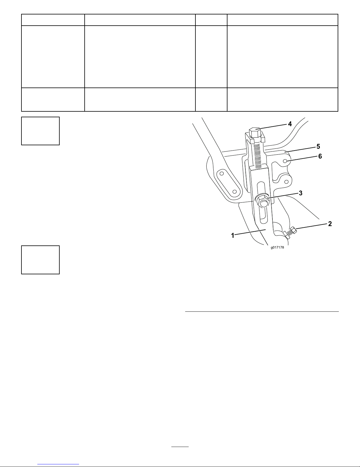
1.Reeldrivebelt3.Drivepulley
2.Idlerpulley4.Flat-headscrew
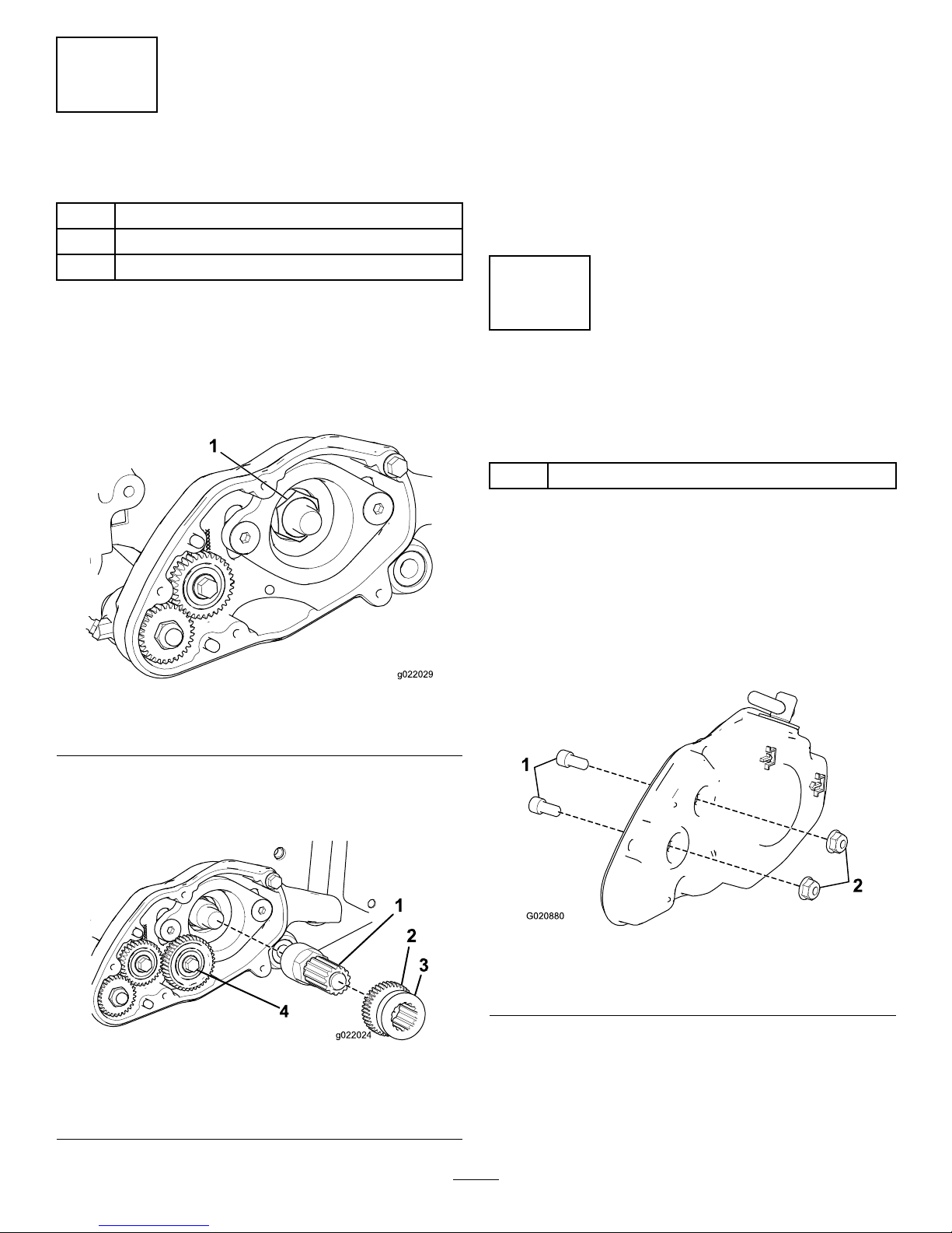
3.Usinga1/2inchdriveratchetandextension,
removethedrivepulleyfromthereelshaft
(Figure18).
Note:Thedrivepulleyhasright-handthreads.
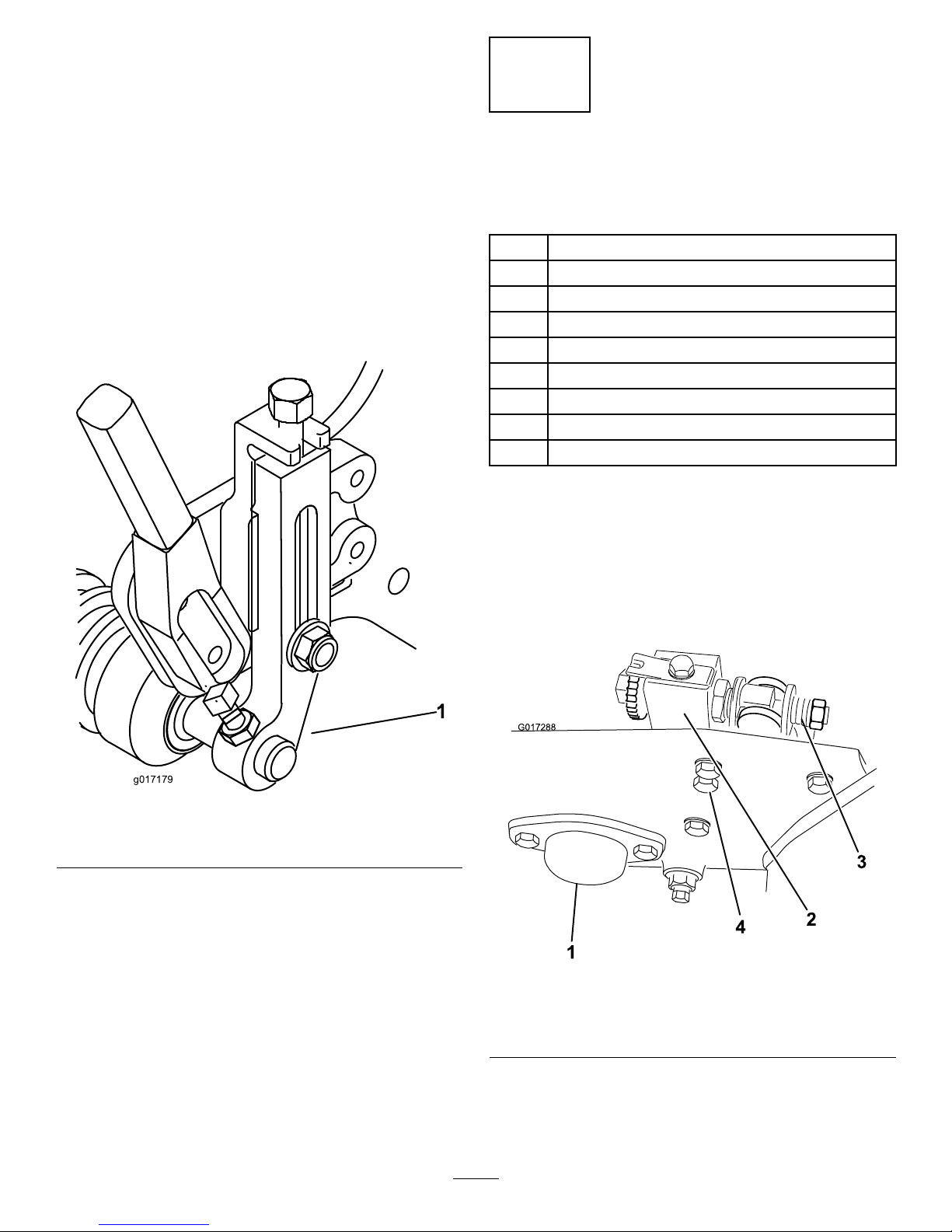
4.Securethereelfromturningwithawoodblock.
5.Removethe2at-headscrewsandnuts
securingthegroomerarmcovertothebearing
housingandsideplate(Figure18).
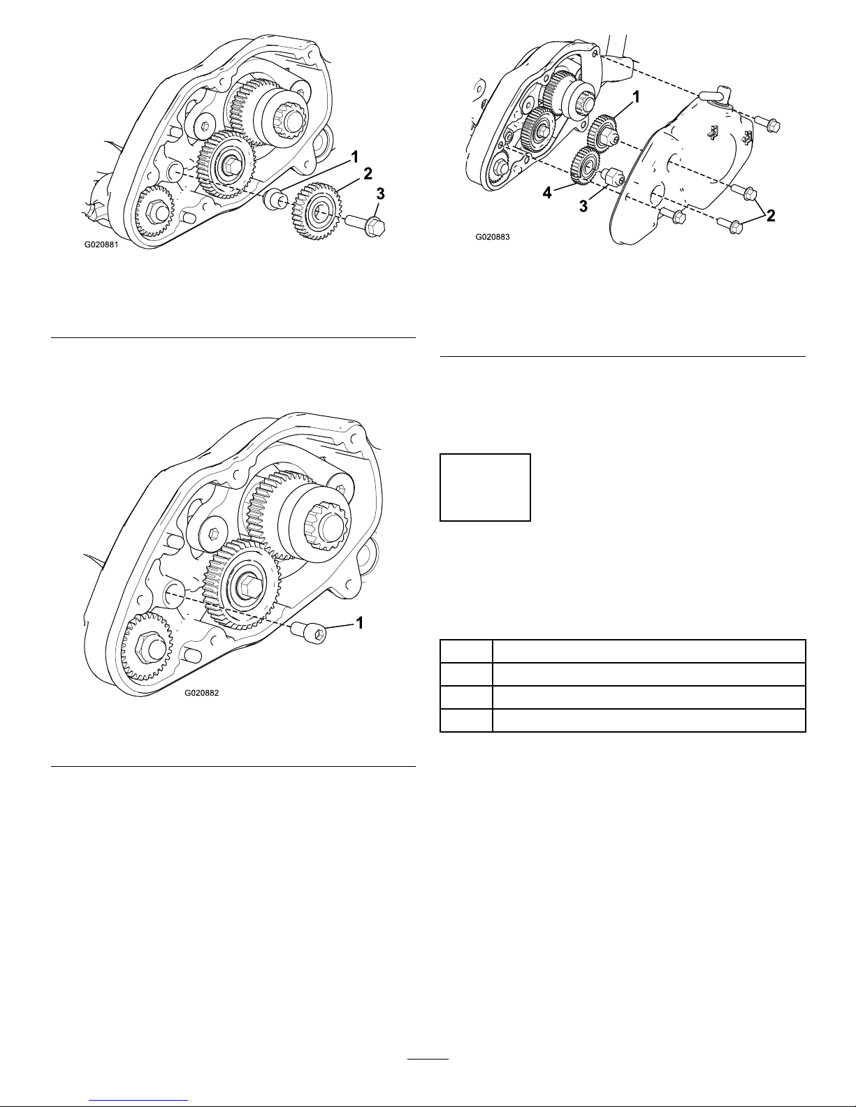
6.Removethegroomerarmcover(Figure19);
retaintheat-headscrewsanddiscardthe
spacersunderthecover.
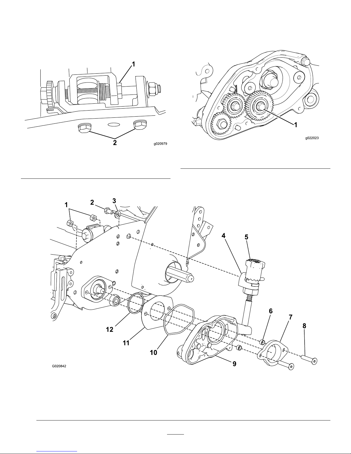
7.IfyouareinstallingthiskitonaGreensmaster
800mowerwithaserialnumberpriorto
230999999,aGreensmaster1000mower
withaserialnumberpriorto229999999,or
aGreensmaster1600mowerwithaserial
numberpriorto260001401,removethe2bolts
andwasherssecuringtherightbedbaradjuster
frametothesideplate.
8.Removethecurvedwasherandthebolt(3/8x
5/8inch)fromtheadjustment-knob,mounting
block(Figure19).
9.Insertanadapterringintothereel-bearing
housing(Figure19).
g020847
Figure19
1.Flat-headscrew4.Spacer7.Bolt
2.Groomerarmcover5.Adjustment-knob,mountingblock8.Adapterring
3.Bearingadapter6.Curvedwasher9.Groomer-plateassembly
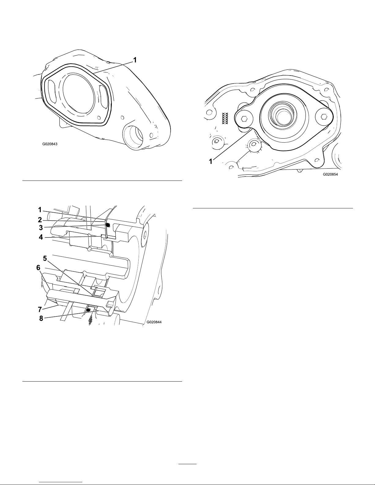
10.Insertthe2at-headscrews(3/8x2inch)
throughthegroomerarmcoverandthebearing
adapterandputaspacerovereachscrew
(Figure19).
11.Installthegroomerarmcover,bearingadapter,
spacers,andgroomer-plateassemblyto
thereel-bearinghousing,slidingtheadapter
throughthebronzebushinginthegroomerplate
assemblyandintothereelbearinghousing
(Figure19).
12.Installthelocknutsontheat-headscrewsand
torquethemto31to37N∙m(23to27ft-lb).
13.Securethemountingblockofthegroomer
adjustmentknobassemblytotherightsideplate
withthebolt(3/8x5/8inch)andcurvedwasher
removedpreviously(Figure19).
9

14.IfyouareinstallingthiskitonaGreensmaster
800mowerwithaserialnumberpriorto
230999999,aGreensmaster1000mower
withaserialnumberpriorto229999999,or
aGreensmaster1600mowerwithaserial
numberpriorto260001401,installtheright,
bedbar-adjusterframetothesideplatewiththe
boltsandwashersyouremovedpreviously.
15.Usinga1/2inchdriveratchetandextension,
installthedrivepulley(right-handthreads)tothe
reelshaft(Figure20).
g017188
1
2
3
4
g017188
Figure20
1.Drivepulley3.Quick-uplever
2.Idlerpulley4.Microadjustmentknob
16.Securethereelfromturningwithawoodblock.
17.Torquethepulleyto54to81N∙m(40to60ft-lb).
18.Installreeldrivebeltandcheckthebelttension
bypressingthebeltatthemidspanofthe
pulleyswith1.5to2.5kg(3to5lb)offorce.
Thebeltshoulddeect6mm(1/4inch).
Repositiontheidlerpulleytoadjustthebelt
tension.Tightenthescrewsonceyouachieve
thepropertension.
19.Installthereel-drive-beltcovertothesideplate
asfollows:
•Greensmaster800mowers—installthereel
drivecovertothesideplatewiththe4bolts
youremovedpreviously.
•Greensmaster1000/1600mowers—install
thecoverusingtheupperandlowerbolts
removedpreviouslyandtheweightandnew
fastenersasshowninFigure21.Usethe
fastenerretainersasrequiredbyyourlocal
codes.
g020853
Figure21
1.Bolt3.Weight
2.Starwasher4.Fastenerretainer
8
InstallingtheGrooming
Reel
Partsneededforthisprocedure:
4Groomer-shaftclamp
4Socket-headscrew(1/4x1-1/4inches)
1Groomerreel(obtainseparately)
Procedure
1.Obtainagroomerreelappropriateforyour
needsandcuttingunit;refertothefollowing
tableforalistofgroomerreels:
ModelNumberGroomer
0428018inchgroomer,springsteel
0428118inchgroomer,carbide
0428218inchgroomer,brush
0428321inchgroomer,springsteel
0428421inchgroomer,carbide
0428521inchgroomer,brush
0428626inchgroomer,springsteel
0428726inchgroomer,carbide
0428826inchgroomer,brush
0426818inchsoftgroomingbrush
0426918inchstiffgroomingbrush
0427021inchsoftgroomingbrush
0427121inchstiffgroomingbrush
0427626inchstiffgroomingbrush
10

2.Looselyinstallthe2halvesofagroomer-shaft
clamptothedrivenshaftontherightsideofthe
machine(Figure22andFigure23).
g020851
Figure22
1.Socket-headscrew
2.Socket-headscrew—looselyinstalledintheclamp
g020850
Figure23
1.Groomerreel3.Socket-headscrew
2.Groomer-shaftclamp
3.Slidethegroomer-reelshaftintotheclampon
therightsideandswingituptothedriveshaft
ontheleft(Figure22).
Important:Ifinstallingacarbide-toothed
groomer,ensurethattheteethpointin
thedirectionthegroomerwillrotatewhen
installed.
4.Securethegroomerreelwiththeclampsas
showninFigure22andFigure23,torquingthe
socketheadscrewsto9.6to10.5N∙m(85to
95in-lb).
5.Checktheassemblyofthegroomer.
6.Rotatebothquick-upleverstoraisethe
groomingreelintothetransportposition(Figure
20).
7.Correctanyproblemsandrechecktheassembly.
8.Usingahand-pumpgreasegun,lubricatethe2
groomer-shaftbearings(oneoneachend).
Note:Pumponly2to3pumpsmaximumto
avoidpermanentlydamagingthegreaseseals.
9.Centertherollerbetweentheheight-of-cutarms
andtightenthesetscrewsandjamnuts.
Operation
Grooming
Groomingisperformedintheturfcanopyabovethe
soillevel.Groomingpromotesverticalgrowthofgrass
plants,reducesgrain,andseversstolonsproducing
adenserturf.Groomingproducesamoreuniform
andtighterplayingsurfaceforfasterandtrueraction
ofthegolfball.
Verticuttingisamoreaggressivecultivationtechnique
designedtoremovethatchbycuttingthrough
theturfcanopyandintothethatch/matlayer.
Groomingshouldnotbeconsideredareplacementfor
verticutting.Verticuttingisgenerallyamorerigorous
andperiodictreatmentthatcantemporarilydamage
theplayingsurface,whilegroomingisaroutineand
gentlertreatmentdesignedtomanicuretheturf.
g006671
Figure24
1.Grassrunners2.Thatch
Groomingbrushesareamorerecentdevelopment
whicharedesignedtobelessintrusivethan
conventionalgroomingbladeswhenadjustedto
lightlycontacttheturfcanopy.Brushingmaybemore
benecialfortheultra–dwarfcultivars,sincethese
grasstypeshavemoreofauprightgrowthpattern
anddonotllinthatwellthroughhorizontalgrowth.
Brushes,however,caninjureleaftissueiftheyareset
topenetratetoodeeplyintothecanopy.
Groomingissimilartoverticuttinginitsrunnercutting
action.Groomingbladeshowever,shouldnever
penetratethesoillikeverticuttingordethatching.
Groomerbladesarespacedclosertogetherandare
usedmoreoftenthanverticutterssothattheyare
moreeffectiveincuttingrunnersandremovingthatch.
Becausegroominginjuresleaftissuetosomedegree
itshouldbeavoidedduringperiodsofhighstress.
11

Coolseasonspeciessuchascreepingbentgrass
andannualbluegrassshouldnotbegroomedduring
hightemperature(andhighhumidity)periodsin
midsummer.
Itisdifculttomakepreciserecommendationsonuse
ofgroomingreelsbecausesomanyvariablesaffect
theperformanceofgrooming,including:
•Thetimeoftheyear(i.e.,thegrowingseason)and
weatherpattern
•Thegeneralconditionofeachgreen
•Thefrequencyofgrooming/cutting—bothhow
manycuttingsperweekandhowmanypasses
percutting
•Theheight-of-cutsettingonthemainreel
•Theheight/depthsettingonthegroomingreel
•Howlongthegroomingreelhasbeeninuseon
thisgreen
•Thetypeofgrassonthegreen
•Theoverallgreensmanagementprogram(i.e.
irrigation,fertilizing,spraying,coring,overseeding,
etc.)
•Trafc
•Stressperiods(i.e.,hightemperatures,high
humidity,unusuallyhightrafc)
Thesefactorscanvaryfromgolfcoursetogolfcourse
andfromgreentogreen.Inspectthegreensfrequently
andvarythegroomingpracticeinaccordancewith
theneed.
Thegroomerissetatthefactorywith13mm(1/2
inch)bladespacing.Byremovingspacersandadding
bladesoraddingspacersandremovingbladesthe
groomercanbechangedto6mm(1/4inch)or19mm
(3/4inch)spacing.
Groomingwith6mm(1/4inch)bladespacingis
recommendedforfastgrowthperiods(springthrough
earlysummer).Groomingwith19mm(3/4inch)blade
spacingisrecommendedforslowergrowthperiods
(latesummerthroughfallandwinter).Donotusethe
groomingreelduringhighstressperiods.
Note:Groomingwith6mm(1/4inch)bladespacing
removesmoregrassbladesandthatchandcutsmore
runnersthangroomingwith13mm(1/2inch)or19
mm(3/4inch)bladespacing.Ifgroomingwith6mm
(1/4inch)bladespacing,oneortwogroomingsper
weekshouldbesufcientexceptduringmaximum
growthperiods.
Note:Thepracticeofchangingthedirectionofcut
eachtimethegreeniscutshouldbecontinuedwhen
agroomerisused.Thisrotationwillenhancethe
effectsofthegrooming.
TestingtheGroomer
Performance
Important:Improperorover-aggressiveuseof
thegroomingreel(i.e.,toodeeportoofrequent
grooming)maycauseunnecessarystressonthe
turf,leadingtoseveregreensdamage.Usethe
groomercautiously.
Itisimportanttodeterminetheperformanceofthe
groomerbeforeputtingitintoregularuseongreens.
Westronglysuggeststhataformaltestprocedurebe
used.Thefollowingisapracticalwayofdetermining
theproperheight/depthsetting:
1.Placethecuttingunitonaatlevelsurface.
2.Setthecuttingreeltotheheightofcutthatwould
normallybeusedwithoutthegroomingreel.Use
aWiehlerollerandscraperforthefrontroller.
3.Setthegroomingreel1/2theheight-of-cut
settingabovetheground(e.g.for3.2mm(1/8
inch)height-of-cutsetting,setthegroomerat
1.6mm(1/16inch)abovetheground).
Note:Ifusingthegroomerbrush,setitatthe
height-of-cutsettingabovetheground(e.g.for
3.2mm(1/8inch)height-of-cutsetting,setthe
groomerat3.2mm(1/8inch)abovetheground).
4.Makeapassoverthetestgreen,thenlowerthe
groomerushwiththegroundlevelandmake
anotherpassoverthetestgreen.
Note:Ifusingthegroomerbrush,loweritto1/2
theheight-of-cutsettingabovetherollerlevel
(e.g.for3.2mm(1/8inch)height-of-cutsetting,
setthegroomerat1.6mm(1/16inch)abovethe
ground).
5.Comparetheresults.Therstgroomedarea
whenthesettingwas1/2theheight-of-cut
settingabovetherollerlevelwillhaveremoved
signicantlylessgrassandthatchthanthe
secondsetting.
Checkthetestgreen2or3daysaftertherst
groomingforgeneralcondition/damage.Ifthe
groomedareasareturningyellow/brown,and
thenon-groomedareasaregreen,thenthe
groomingwastooaggressive.
Note:Thecolorofthegrasswillchange
whenyouusethegroomingreel.Youcan
observethiswiththerstgroominganditwill
continueovertime.Experiencewillallowthe
greenssuperintendenttojudgebythecolorof
theturf(alongwithcloseexamination)ifthe
currentgroomingpracticeisappropriateforthe
particulargreen.Becausethegroomingreel
standsupmoregrassandremovesthatch,the
12

qualityofthecutwillnotbethesameaswithout
thegroomer.Youwillnoticethiseffectmostthe
rstfewtimesagroomerisusedonagreen.
Note:Onmultiplepasses(i.e.,doubleandtriple
cutting),thegroomerwillcontinuetopenetrate
deeperoneachsuccessivepass.Multiple
passesarenotrecommended.
6.Afteryoutesttheperformanceofthegroomeron
atestgreenandobtainsatisfactoryresults,you
canbegingroomingontheplayinggreens.Itis
importanttorealize,however,thateachgreen
mayresponddifferentlytogrooming.Inaddition,
growingconditionsareconstantlychanging.
Inspectthegroomedgreensfrequentlyand
makeadjustmentstothegroomingprocedure
asoftenasnecessary.
SettingtheHeight/Depthof
theGroomer
Setthegroomerbladeheight/depthusingthefollowing
procedure:
1.Makesurethattherollersarecleanandthe
mainreelissettothedesiredheightofcut.Park
themachineonaat,levelworksurface.
2.Usethequick-uplevers(bothsides)tolowerthe
groomingreelintothegroomingposition(Figure
25).
g017189
1
2
g017189
Figure25
1.Quick-uplever2.Microadjustmentknob
3.Ononeendofthegroomershaft,measurethe
distancefromthelowesttipofagroomerblade
totheworksurface(Figure26).
1 2 3 4 5 6 7 8 9 10 1 1 12
g017190
g017190
Figure26
4.Liftandturnthemicroadjustmentknob(Figure
25)toraiseorlowerbladetip.
Note:Eachnotchonthemicroadjustment
knobisapproximatelyequalto0.17mm(0.007
inch)ofgroomerdepth.
5.Repeatthisprocedureontheoppositeendof
thegroomer,thenrecheckthesettingontherst
side.
6.Putthegroomingreelintothetransportposition.
TurningtheGroomerOn
andOff
Youcanturnthegroomeronoroffbyrotatingthe
groomer-driveclutchasshowninFigure27.
13

g020855
Figure27
1.Groomer-driveclutch3.Off
2.On
TransportingtheGroomer
Whentransportingmachinebesuretoraisethe
groomingreelintoitstransport(raised)position.
Toraisethegroomingreel,rotatetherightandleft
quick-upleverssotheyfacetotherear(Figure25).
Tolowerthegroomingreel,turnthequick-uplevers
forward.
Maintenance
Cleaning
Hoseoffthegroomingreelafteruse.Donotdirectthe
waterstreamdirectlyatthegroomerbearingseals.
Donotpermitthegroomingreeltostandinwaterso
thatthecomponentsrust.
Lubrication
Usingahand-pumpgreasegun,lubricatethe2
groomer-shaftbearings(oneoneachend).Pump
only2to3pumpsmaximumtoavoidpermanently
damagingthegreaseseals.
Note:Whenlubricatingthemainreelbearings,do
notovergreasebecauseexcessgreasecanworkits
wayintothegroomer-driveboxordripontotheturf.
Every500operatinghours,removethecoverfrom
thegroomer-drivebox.Cleanoutalloftheoldgrease
andpackitwith85g(3.0oz)ofsyntheticgrease(T oro
partnumber125-3511orequivalentsyntheticgrease
meetingISOVG220,NLGI2standards).
InspectingtheBlades
Inspectthegrooming-reelbladesfrequentlyfor
damageandwear.Straightenbentbladeswitha
pliers.Replacewornblades.Wheninspectingthe
blades,checktoseethattherightandleftbladeshaft
endnutsaretight.
Note:Ifusingspringsteelblades,whenonesideof
thebladesbecomeworn,removethegroomingreel,
rotateit180degrees,andinstallitsothattheunworn
sideisfacingthedirectionofrotation.
Note:Becausethegroomermayintroducemore
debris(i.e.,dirtandsand)intothecuttingunitthan
whatthereelwouldnormallybeexposedto,the
bedknifeandmainreelshouldbecheckedforwear
morefrequently.Thisisespeciallyimportantinsandy
soiland/orwhenthegroomerissetforpenetration.
ReplacingtheGrooming
Reel
Removeandreplacethegroomingreelusingthe
followingprocedure:
1.Removebothsocket-headscrewsandshaft
clampsfromonesideofthegroomerreel(Figure
23).
2.Removetheinnersocket-headscrewfromthe
clampontheothersideandloosentheouter
screw.
g020852
Figure28
1.Socket-headscrew
2.Socket-headscrew—looselyinstalledintheclamp
3.Slidethereelassemblyoutoftheclamp.
4.Referto8InstallingtheGroomingReel(page
10)toinstallthereelasneeded.
5.Checkthegroomingreelheight/depthsetting.
14

Notes:

DeclarationofIncorporation
TheT oroCompany,8111LyndaleAve.South,Bloomington,MN,USAdeclaresthatthefollowingunit(s)
conform(s)tothedirectiveslisted,wheninstalledinaccordancewiththeaccompanyinginstructionsontocertain
ToromodelsasindicatedontherelevantDeclarationsofConformity.
ModelNo.SerialNo.ProductDescriptionInvoiceDescriptionGeneralDescriptionDirective
04134—
GroomerDrive
System,Greensmaster
800/1000/1010/1600/1610
Mower
GROOMERDRIVE,
FIXEDHEADLawnMower2006/42/EC,
2000/14/EC
RelevanttechnicaldocumentationhasbeencompiledasrequiredperPartBofAnnexVIIof2006/42/EC.
Wewillundertaketotransmit,inresponsetorequestsbynationalauthorities,relevantinformationonthispartly
completedmachinery.Themethodoftransmissionshallbeelectronictransmittal.
ThismachineryshallnotbeputintoserviceuntilincorporatedintoapprovedT oromodelsasindicatedonthe
associatedDeclarationofConformityandinaccordancewithallinstructions,wherebyitcanbedeclaredin
conformitywithallrelevantDirectives.
Certied:AuthorizedRepresentative:
MarcelDutrieux
ManagerEuropeanProductIntegrity
ToroEuropeNV
Nijverheidsstraat5
2260Oevel
Belgium
JohnHeckel
Sr.EngineeringManagerTel.+3216386659
8111LyndaleAve.South
Bloomington,MN55420,USA
March7,2017
Table of contents
Other Toro Lawn Mower Accessories manuals
Popular Lawn Mower Accessories manuals by other brands

Husqvarna
Husqvarna 110164 / CZ42 Operator and parts manual

Dixon
Dixon SpeedZTR 539 131354 Operator and parts manual

Craftsman
Craftsman 917.249660 owner's manual

Cub Cadet
Cub Cadet 59A30044150 Operator's manual

Cub Cadet
Cub Cadet Timing Deck Striper/Roller Operator's manual

Stiga
Stiga VILLA 107M user manual

Snapper
Snapper 6-1410 installation instructions

Exmark
Exmark Ultra Vac QDS Lazer Z HP Setup instructions

WilTec
WilTec 50800 Operation manual

Land Pride
Land Pride Accu-Z Z60 Operator's manual

Classic Accessories
Classic Accessories 73117 Instructions & Care

Craftsman
Craftsman BRUSH GUARD 486.246283 Operator's manual