Maintenance
•Ensurethatthebrushisparalleltotherollerwith
1.5mm(0.060inch)clearancetolightcontact.
•Greasethettingsevery50hoursandafterevery
washing.
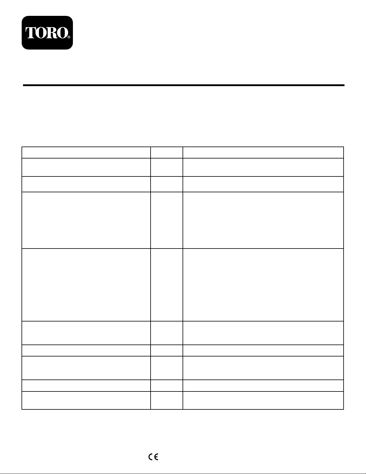
•Whenreplacingarollerbrush,torquetheJ-bolts
to2to3N∙m(20to25in-lb).
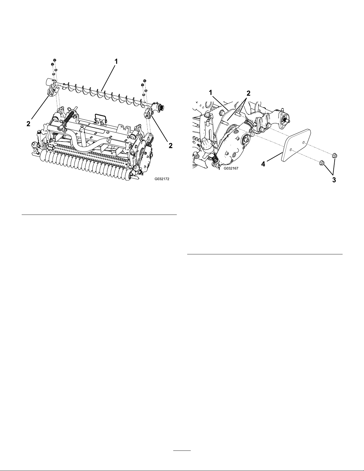
•Whenreplacingthebrush-shaft-drivenpulley,
torquethenutto36to45N∙m(27to33ft-lb).
•Whenreplacingthebrush-drivepulley,apply242
Loctite(blue)andtorquetheboltto20to26N∙m
(15to19ft-lb).
Note:Therollerbrush,theidlerbearing,andthebelt
areconsideredconsumableitems.
CheckingthePulley
Alignment
Important:Ensurethatthebeltisproperly
tensionedpriortocheckingthealignment.
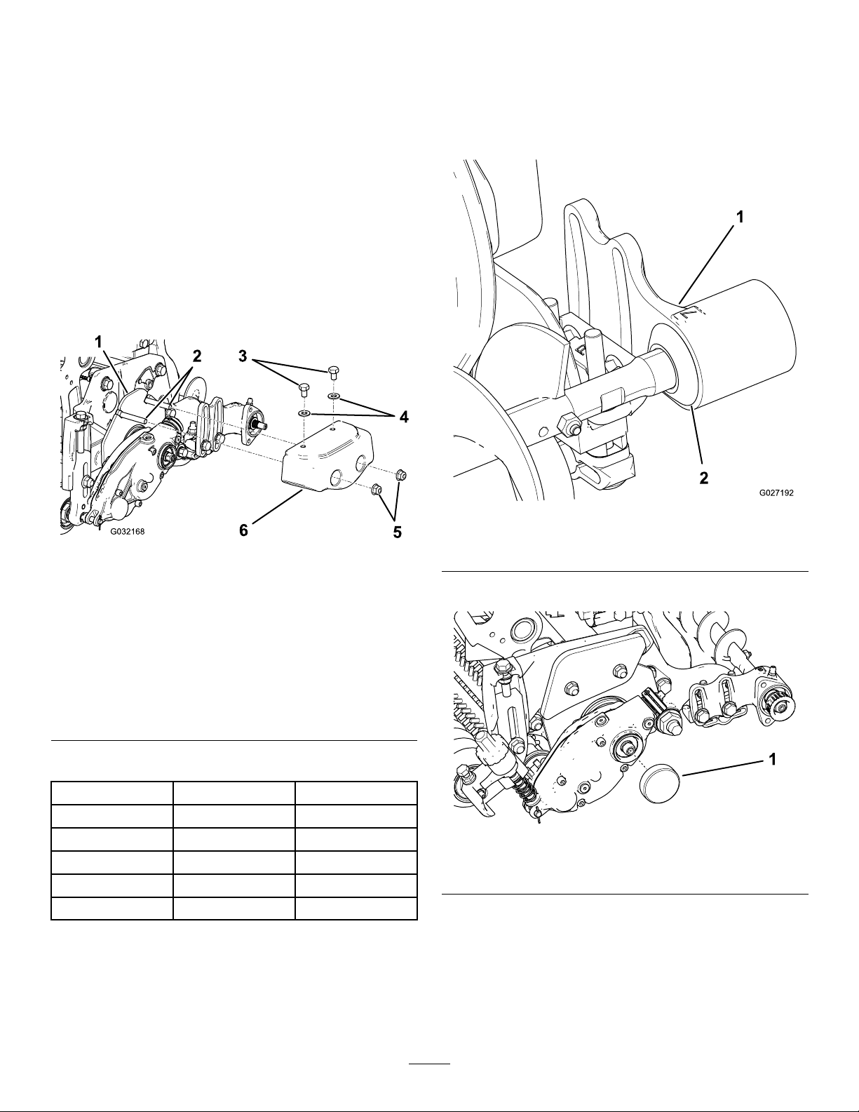
1.Layastraightedgealongtheouterfaceofthe
drivepulley(Figure21).
Important:Onlylaythestraightedgeacross
thedrivepulley,donotlayitacrossthedrive
andthedrivenpulley.
2.Ensurethattheouterfacesofthedrivepulley
andthedrivenpulleyareinlinewithin0.76mm
(0.030inch).
Important:Donotusetheidlerpulleyto
checkthealignment.
3.Ifthepulleysarenotaligned,refertoAdjusting
thePulleyAlignment(page10).
Important:Thebeltmayfailprematurelyif
thepulleysarenotproperlyaligned.
g192350
Figure21
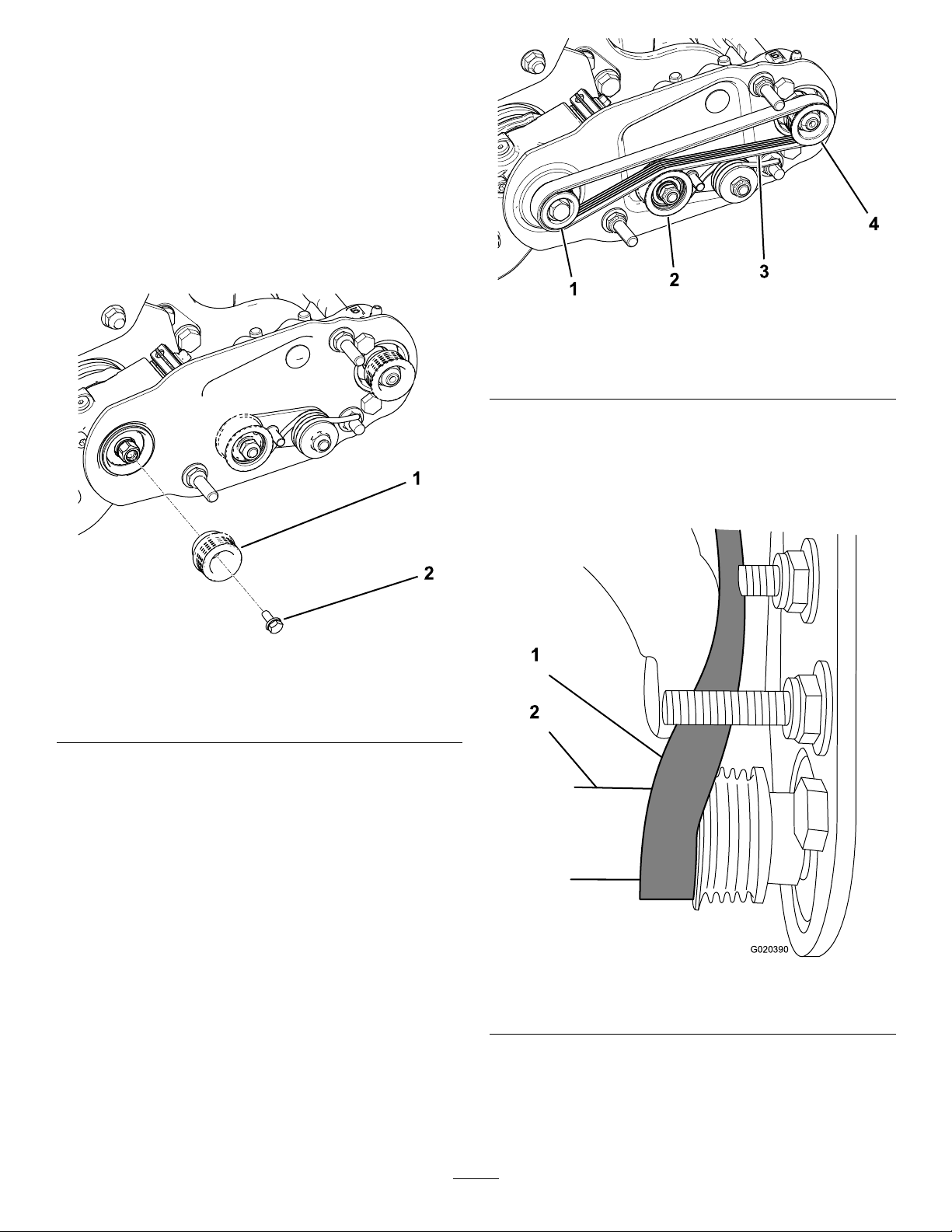
AdjustingthePulley
Alignment
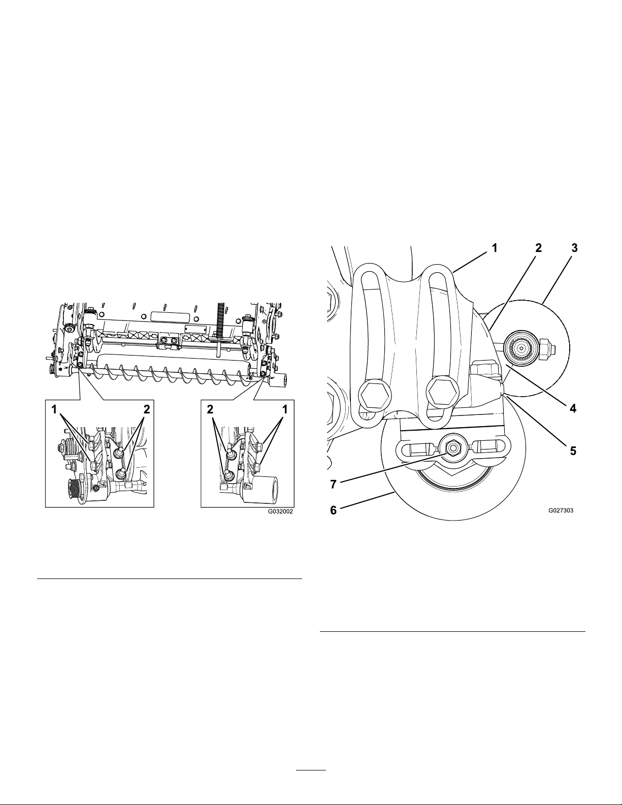
1.Thedrivenpulley(attheroller-brushshaft)can
moveinorout(Figure22).
Note:Makenoteofwhichwaythepulleyneeds
tomovewhencheckingthebeltalignment;refer
toCheckingthePulleyAlignment(page10).
g193169
Figure22
1.Drivepulley3.Drivenpulley
2.Idlerpulley4.Driven-pulleynut
2.Whilerotatingthereel,whichrotatesthedrive
pulley,prythebeltoffthedrivepulley(Figure22
Important:Wearapaddedgloveorusea
heavyragtorotatethereel.
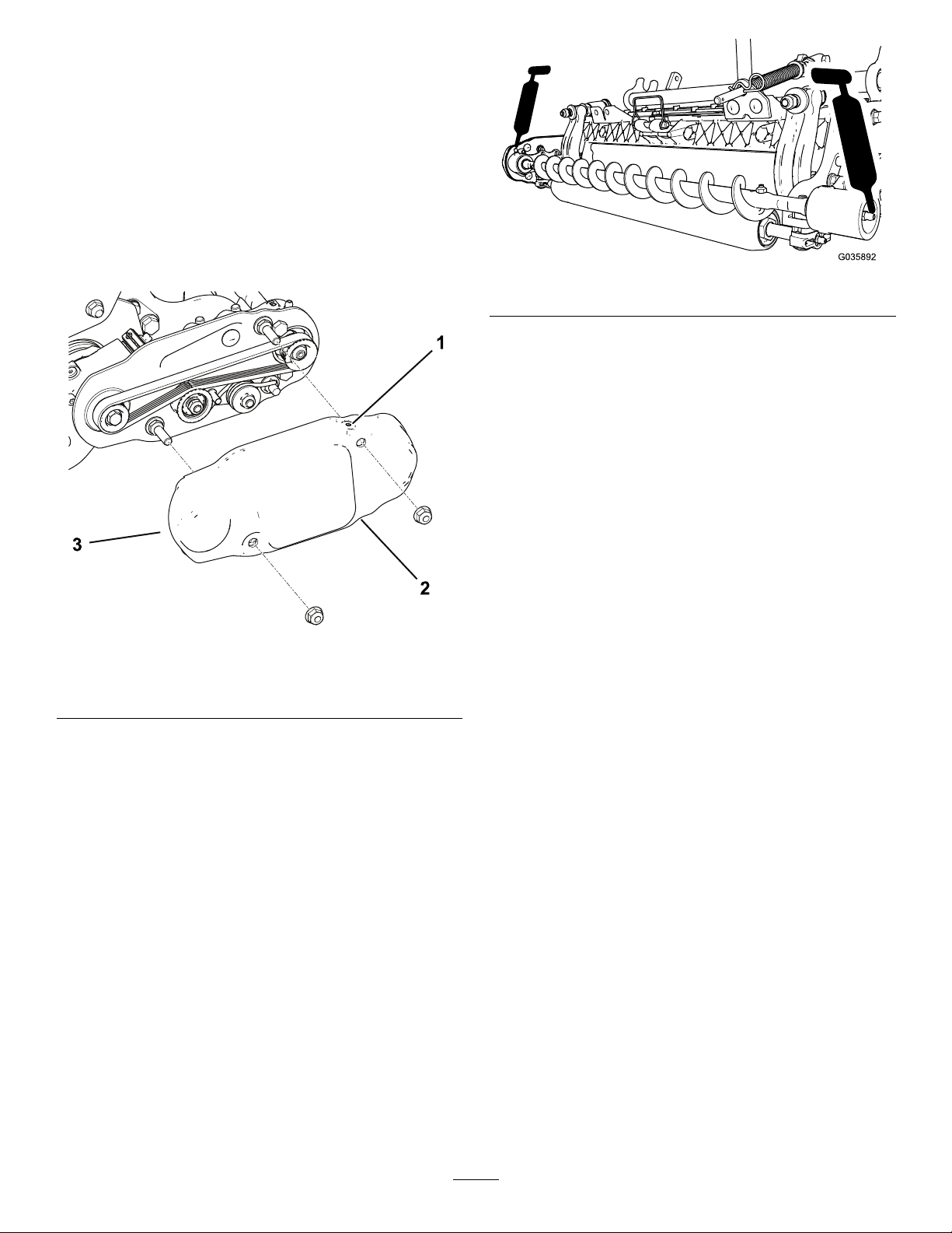
3.Removethelocknutsecuringthedrivenpulley
tothebrushshaft(Figure22orFigure23).
Note:Usea1/2-inchwrenchontheroller-brush
shaftatstokeepitfromrotating.
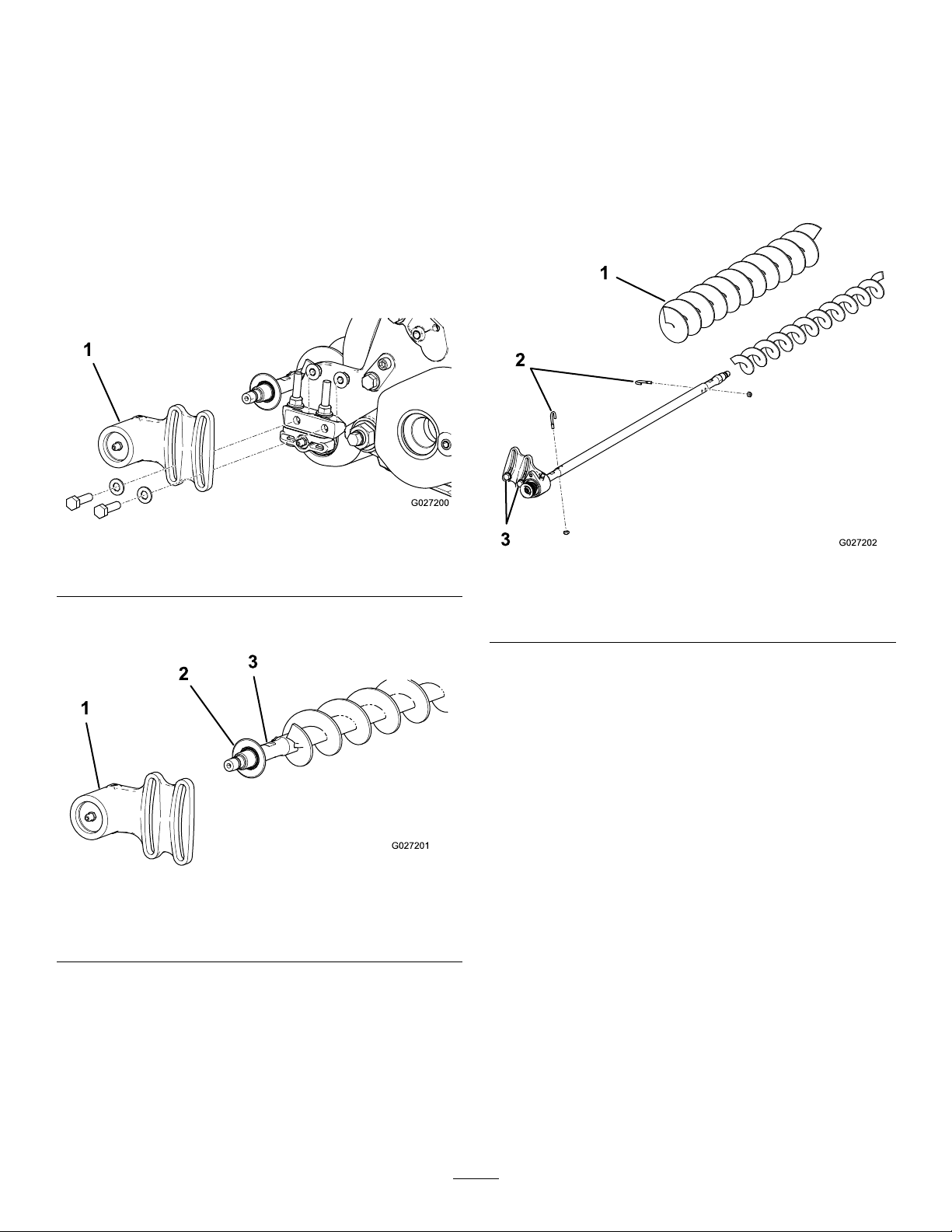
4.Removethedrivenpulleyfromtheshaft(Figure
23).
5.Ifthepulleyneedstomoveout,adda0.8mm
(0.032inch)thickwasher(Figure23).
Note:Ifthepulleyneedstomovein,remove
theexisting0.8mm(0.032inch)thickwasher.
6.InstallthepulleyasshowninFigure23.
10