manuals.online logo
Brands
  1. Home
  2. •
  3. Brands
  4. •
  5. Toro
  6. •
  7. Lawn Mower Accessories
  8. •
  9. Toro 04259 User manual

Toro 04259 User manual

Other Toro Lawn Mower Accessories manuals

Toro 161-4450 User manual

Toro

Toro 161-4450 User manual

Toro 145-3530 User manual

Toro

Toro 145-3530 User manual

Toro 02710 Manual

Toro

Toro 02710 Manual

Toro CT Series User manual

Toro

Toro CT Series User manual

Toro 04294 User manual

Toro

Toro 04294 User manual

Toro 07142 User manual

Toro

Toro 07142 User manual

Toro 161-3138 User manual

Toro

Toro 161-3138 User manual

Toro 140-5036 User manual

Toro

Toro 140-5036 User manual

Toro 74254 User manual

Toro

Toro 74254 User manual

Toro Recycler 126-8701 User manual

Toro

Toro Recycler 126-8701 User manual

Toro 79161 User manual

Toro

Toro 79161 User manual

Toro Pro Sweep 5200 User manual

Toro

Toro Pro Sweep 5200 User manual

Toro 111-8083 User manual

Toro

Toro 111-8083 User manual

Toro 140-2054 User manual

Toro

Toro 140-2054 User manual

Toro Super Recycler 115-8416 User manual

Toro

Toro Super Recycler 115-8416 User manual

Toro 139-1000 User manual

Toro

Toro 139-1000 User manual

Toro 79392 User manual

Toro

Toro 79392 User manual

Toro 133-0150 User manual

Toro

Toro 133-0150 User manual

Toro 133-0575 User manual

Toro

Toro 133-0575 User manual

Toro 79485 User manual

Toro

Toro 79485 User manual

Toro 30667 User manual

Toro

Toro 30667 User manual

Toro 31527 User manual

Toro

Toro 31527 User manual

Toro 161-4520 User manual

Toro

Toro 161-4520 User manual

Toro Greensmaster 3320 TriFlex User manual

Toro

Toro Greensmaster 3320 TriFlex User manual

Popular Lawn Mower Accessories manuals by other brands

Ariens 891008 Operator's manual

Ariens

Ariens 891008 Operator's manual

Rover 108 - 109 owner's manual

Rover

Rover 108 - 109 owner's manual

Snapper 1690047 Operator's manual

Snapper

Snapper 1690047 Operator's manual

RHINO 800 Operator's manual

RHINO

RHINO 800 Operator's manual

Exmark Quest 126-7506 Operator's manual

Exmark

Exmark Quest 126-7506 Operator's manual

Snapper 1685167 installation instructions

Snapper

Snapper 1685167 installation instructions

Cub Cadet 19B70029100 installation manual

Cub Cadet

Cub Cadet 19B70029100 installation manual

Stihl AMK 043.1 instruction manual

Stihl

Stihl AMK 043.1 instruction manual

MTD 753-0873 Service kit manual

MTD

MTD 753-0873 Service kit manual

Bush Hog RG60 Operator's manual

Bush Hog

Bush Hog RG60 Operator's manual

Scag Power Equipment GC-F4 Operator's manual

Scag Power Equipment

Scag Power Equipment GC-F4 Operator's manual

Land Pride RCF2760 Operator's manual

Land Pride

Land Pride RCF2760 Operator's manual

Peco SPARTAN RZ Series Operator's manual

Peco

Peco SPARTAN RZ Series Operator's manual

Peco 28621206 Operator's manual

Peco

Peco 28621206 Operator's manual

Simplicity 367 Operator's manual

Simplicity

Simplicity 367 Operator's manual

Simplicity 211 Operator's manual

Simplicity

Simplicity 211 Operator's manual

Iseki SSM72 Operators & service manual

Iseki

Iseki SSM72 Operators & service manual

Simplicity 1690043 Operator's manual

Simplicity

Simplicity 1690043 Operator's manual

manuals.online logo
manuals.online logoBrands
  • About & Mission
  • Contact us
  • Privacy Policy
  • Terms and Conditions

Copyright 2025 Manuals.Online. All Rights Reserved.

FormNo.3390-846RevC
Forward-RotatingGroomerDrive
System-GreensmasterFlex™1800/2100and
eFlex®1800/2100Mower
ModelNo.04259
InstallationInstructions
Thefollowinggroomerreelsarealsoavailableforthis
product:
•18-inchcarbidegroomer
•18-inchspiralbrush
•18-inchsoftgroomingbrush
•18-inchstiffgroomingbrush
•18-inchspringsteelgroomer
•18-inchthinspringsteelgroomer
•21-inchspringsteelgroomer
•21-inchcarbidegroomer
•21-inchspiralbrush
•21-inchsoftgroomingbrush
•21-inchstiffgroomingbrush
•21-inchthinspringsteelgroomer
ContactyourAuthorizedToroDistributorformore
information.
WARNING
CALIFORNIA
Proposition65Warning
Thisproductcontainsachemical
orchemicalsknowntotheStateof
Californiatocausecancer,birthdefects,
orreproductiveharm.
LooseParts
Usethechartbelowtoverifythatallpartshavebeenshipped.
DescriptionQty.Use
Locknut(3/8x16inch)4
Rightdrivecover1
Groomerbelt1
Groomerdrive1
Shoulderbolt2
Extensionspring1
Rightdrivesideplate1
Shimplate1
Rightgroomerarm1
Bolt(M6)2
Bushing2
Springwasher2
Locknut(3/8x24inch)2
Leftsupportplate1
Leftgroomerarm1
Washer2
Rollerheightspacer6
Bolt(1/4inch)4
Drivenpulley1
Innercompressionspring2
Outercompressionspring2
Installthegroomerdrivesystemandareelorbrush.
©2017—TheToro®Company
8111LyndaleAvenueSouth
Bloomington,MN55420
Registeratwww.T oro.com.OriginalInstructions(EN)
PrintedintheUSA
AllRightsReserved*3390-846*C
InstallingtheGroomer
DriveSystem
Important:Readtheseinstructionsthoroughly
beforesettinguporoperatingthegroomer.
Failingtofollowsetuporoperatinginstructionsin
thismanualmayresultindamagetothecutting
unitand/orthegroomerortheturf.
Note:Determinetheleftandrightsidesofthe
machinefromthenormaloperatingposition.
1.Separatethecuttingunitfromthetractionunit.
RefertotheOperator'sManualforprocedure.
2.Loosenthescrewssecuringeachendofthe
frontrollertotheheight-of-cutarms(Figure1).
G016224
g016224
Figure1
1.Rollermountingscrews3.Carriagebolt,washer,and
locknut
2.Height-of-cutarm4.Adjustingscrew
3.Removetheplowbolts,washers,andlocknuts
securingtheheight-of-cutarmstoeachendof
cuttingunit(Figure1).Removetheheight-of-cut
armsandrollerassembly.
Note:Retainallpartsforuseifthegroomeris
everremoved.
4.Removetheheight-of-cutadjustingscrewsfrom
theheight-of-cutarms(Figure1).
5.Removethe2boltsandnutssecuringthe
counterweighttotherightendofthecuttingunit.
Removethecounterweight(Figure2).
G016289
1
2
g016289
Figure2
1.Counterweight2.Bearingnut
6.Removethebearingnutfromthereelshaft
(Figure2).
7.Loosenthecaptiveboltsecuringthebeltcover
totheleftendofthecuttingunituntilyoucan
removethecover(Figure3).
g017662
1
2
3
4
g017662
Figure3
1.Beltcoverbolt,captive3.Belt
2.Beltcover4.Belttensioningnut
8.Loosenthebelttensioningnutandremovethe
belt(Figure3).
9.Loosenthe2setscrewssecuringthelower
pulleyandremovethepulleyfromthereelshaft
(Figure4).
2
g017633
1
2
g017663
Figure4
1.Lowerpulley2.Setscrew
10.Removethe3boltssecuringthebeltdrive
assemblytothecuttingunitandremovethe
wholeassembly(Figure5).
g017664
1
2
3
g017664
Figure5
1.Leftsupportplate3.Bolts
2.Beltdriveassembly
11.Usealong-noseplierstoremovethe
compressionspringsonbothsidesofthecutting
unitandreplacethemwiththenewinnerand
outercompressionsprings(Figure6).
g028128
Figure6
1.Compressionspring2.Innerandouter
compressionspring
12.Slidetheshimplateontotherearoftheright
driveassemblyasshowninFigure7.
1
23
4
5
G027980
g027980
Figure7
1.Rightdriveassembly4.Shimplate
2.Shoulderbolt5.Pilotbore
3.O-ring
13.PutalightcoatingofgreaseontheO-ringand
thepilotbore(Figure7).
14.Securethedriveassemblyusing2shoulder
boltsasshowninFigure7.
Note:Makesurethatthesideplaterotates
freely.
3
15.Applygreasetothesealsinthedriveassembly
bearingsupportandtotheendofthegroomer
shaft(Figure8).
G027981
2
g027981
Figure8
1.Groomershaft2.Seallip
16.Slidethesplinedendofthegroomershaftinto
thedrive-assemblybearingsupport(Figure8).
17.Applygreasetothesealsurfaceofthedriven
pulley,asshowninFigure9.
Note:Donotputgreaseontheareawherethe
beltwillride.
18.Slidethepulleyontothegroomershaft(Figure
9).
G016228
g016228
Figure9
1.Groomershaft3.Flangelocknut
2.Drivenpulley4.Applygreasehere
19.Securethepulleytotheshaftwithaange
locknutandtorqueto23to28N·m(17to21
ft-lb)(Figure9).
20.Applygreasetothesealintheleftsupportplate
andtotheendofthegroomershaft(Figure9).
21.Insertotherendofthegroomershaftintotheleft
supportplate(Figure5).
22.Installthereelbelt-driveassemblyusingthe
previouslyremovedboltsandensurethatthe
sideplaterotatesfreely(Figure5).
23.Installthelowerpulleyontothereeldriveshaft,
securingitwiththe2setscrewsontothekey
ontheshaft(Figure4).
24.Installthedrivebeltandtensionitasdescribed
inthetractionunitOperator’sManual.
25.Securethegroomerdrivepulleytothereelshaft
ontherightsideofthereelandtorqueitto170
N·m(125ft-lb)(Figure10).
Note:Theuseofanimpactgunisnotenough
toensureproperinstallation.Failuretoproperly
torquethedrivepulleycanresultintheassembly
unscrewingitselfduringoperation.
1
G016218
g016218
Figure10
1.Drivepulley
4
26.Insertabushingintotheholeinthegroomer
driveassembly(Figure11).
1
2
G016215
g016215
Figure11
1.Bushing2.Holeingroomerdrive
27.Threadtheheight-of-cutadjustingscrewintothe
topoftherightadjusterarmassembly(Figure
12).
1
2
G016216
g016216
Figure12
1.Height-of-cutscrew2.Rightadjusterarm
assembly
28.Installtherightadjusterarmassemblytothe
cuttingunitsideplateusingtheexistingplow
bolt,nut,andanewwasher.
Note:Makesurethattherodendofthe
height-of-cutarmassemblyslidesintothe
bushingintheholeinthegroomerdrive
assembly(Figure12).
29.Securetheadjusterarmassemblyrodendto
thegroomerdriveassemblywithaBelleville
washerandlocknut(Figure13).
Note:Donotovertightenthelocknut.The
washershouldbecompressedbutthearmmust
befreetopivot.
1
2
3
G016217
g016217
Figure13
1.Rodendofthe
height-of-cutassembly
3.Bellevillewasher
2.Locknut
30.Inserttherollershaftintotherightadjusterarm
andlooselysecureitwiththebolt(Figure14).
G016229
g016229
Figure14
1.Rollershaftbolt
31.Threadtheheight-of-cutadjustingscrewintothe
topoftheleftadjusterarmassembly(Figure12).
32.Inserttherollershaftintotheleftadjusterarm.
Donottightentheboltatthistime.
33.Installtheleftadjusterarmassemblytothe
cuttingunitsideplateusingtheexistingplow
bolt,nut,andanewwasher(Figure12).
Note:Makesurethattherodendslidesinto
thebushingintheholeinthegroomerdrive
assembly.
34.Securetheadjuster-armassemblyrodendto
thegroomerdriveassemblywithaBelleville
washerandlocknut(Figure13).
5
35.Rotatetheidlerpulleyuntiltheshiftleverspring
canbehookedintotheholeinthepulleybracket
andontothestudasshowninFigure15.
G016230
g016230
Figure15
1.Shiftleverspring
36.Routethebeltontothedriverpulley,idlerpulley,
anddrivenpulleyasshowninFigure16.
G016231
g016231
Figure16
1.Drivebelt
Important:Ensurethatthebeltiscentered
onthepulleysandinthegrooves(Figure17).
g216642
Figure17
37.Mountthebeltcovertothegroomerhousing
assemblywith3locknuts(Figure18).
G016233
g016233
Figure18
1.Beltcover
38.Centertherollerbetweentheadjusterarmsand
tightenthemountingbolts(Figure14).
39.Lubricatethegroomerbearings(Figure19and
Figure20)weeklyorafterevery10operating
hours,beforeextendedperiodsofnon-use,and
immediatelyaftereverywashing.Pumpgrease
intothettingsuntilgreaseispurgedontothe
groomershaft.Wipeexcessgreasefromthe
sealsandshaft.
Note:Operatethegroomerfor30seconds
aftergreasing.Disengagethecuttingunitand
wipeexcessgreasefromthesealsandshaft.
G027982
g027982
Figure19
6
g010436
Figure20
Operation
Introduction
Groomingisperformedintheturfcanopyabovethe
soillevel.Groomingpromotesverticalgrowthofgrass
plants,reducesgrain,andseversstolonsproducing
adenserturf.Groomingproducesamoreuniform
andtighterplayingsurfaceforfasterandtrueraction
ofthegolfball.
Verticuttingisamoreaggressivecultivationtechnique
designedtoremovethatchbycuttingthrough
theturfcanopyandintothethatch/matlayer.
Groomingshouldnotbeconsideredareplacementfor
verticutting.Verticuttingisgenerallyamorerigorous
andperiodictreatmentthatcantemporarilydamage
theplayingsurface,whilegroomingisaroutineand
gentlertreatmentdesignedtomanicuretheturf.
g006671
Figure21
1.Grassrunners(stolons)2.Thatch
Groomingbrushesareamorerecentdevelopment
whicharedesignedtobelessintrusivethan
conventionalgroomingbladeswhenadjustedto
lightlycontacttheturfcanopy.Brushingmaybemore
benecalfortheultra-dwarfcultivars,sincethese
grasstypeshavemoreofauprightgrowthpattern
anddonotllinthatwellthroughhorizontalgrowth.
Brushes,however,caninjureleaftissueiftheyareset
topenetratetoodeeplyintothecanopy.
Groomingissimilartoverticuttinginitsrunnercutting
action.Groomingbladeshowever,shouldnever
penetratethesoillikeverticuttingordethatching.
Groomerbladesarespacedclosertogetherandare
usedmoreoftenthanverticutterssothattheyare
moreeffectiveincuttingrunnersandremovingthatch.
Becausegroominginjuresleaftissuetosomedegree
itshouldbeavoidedduringperiodsofhighstress.
Coolseasonspeciessuchascreepingbentgrass
andannualbluegrassshouldnotbegroomedduring
hightemperature(andhighhumidity)periodsin
midsummer.
Itisdifculttomakepreciserecommendationsonuse
ofgroomingreelsbecausesomanyvariablesaffect
theperformanceofgrooming,including:
•Thetimeoftheyear(i.e.,thegrowingseason)and
weatherpattern
7
•Thegeneralconditionofeachgreen
•Thefrequencyofgrooming/cutting-bothhowmany
cuttingsperweekandhowmanypassesper
cutting
•Theheight-of-cutsettingonthemainreel
•Theheight/depthsettingonthegroomingreel
•Howlongthegroomingreelhasbeeninuseon
thisgreen
•Thetypeofgrassonthegreen
•Theoverallgreensmanagementprogram(i.e.
irrigation,fertilizing,spraying,coring,overseeding,
etc.)
•Trafc
•Stressperiods(i.e.,hightemperatures,high
humidity,unusuallyhightrafc)
Thesefactorscanvaryfromgolfcoursetogolfcourse
andfromgreentogreen.Itisimportant,therefore,to
inspectthegreensfrequentlyandvarythegrooming
practiceinaccordancewiththeneed.
Thegroomerissetatthefactorywith13mm(1/2
inch)bladespacing.The13mm(1/2inch)setting
allowsyoutogroomslightlydeepertocutstolons
withoutthinningouttheturfexcessively.Byremoving
spacersandaddingbladesoraddingspacersand
removingbladesthegroomercanbechangedto6
mm(1/4inch)or19mm(3/4inch)spacing.
Groomingwith6mm(1/4inch)bladespacingis
recommendedforfastgrowthperiods(springthrough
earlysummer)mainlytothinoutthetoplayerof
thecanopy.Groomingwith19mm(3/4inch)blade
spacingisrecommendedforslowergrowthperiods
(latesummerthroughfallandwinter).Duringhigh
stressperiodsitmaybedesirabletonotusethe
groomingreel.
Note:Groomingwith6mm(1/4inch)bladespacing
willtendtoremovemoregrassbladesandthatch
andcutmorerunnersthangroomingwith13mm(1/2
inch)or19mm(3/4inch)bladespacing.Ifyouare
groomingwith6mm(1/4inch)bladespacing,1or2
groomingsperweekwillprobablybesufcientexcept
duringmaximumgrowthperiods.
Note:Thepracticeofchangingthedirectionofcut
eachtimethegreeniscutshouldbecontinuedwhen
agroomerisused.Thisrotationwillenhancethe
effectsofthegrooming.
8
SettingtheHeight/Depthof
theGroomer
Thegroomerbladeheight/depthcanbesetusingthefollowingchart,gures,andprocedure:
RearRoller
SpacersRequired
Height-of-Cut(mm)Height-of-Cut
(inches)
GroomerArm
Position
Height-of-Grooming
Range(mm)
Height-of-Grooming
Range(inches)
01.5mm
3.0mm
4.8mm
6.3mm
0.06inches
0.12inches
0.19inches
0.25inches
A
A
B
B
0.7to1.5mm
1.5to3.0mm
2.2to4.8mm
3.0to6.3mm
0.03to0.06inches
0.06to0.12inches
0.09to0.19inches
0.12to0.25inches
17.8mm
9.6mm
0.31inches
0.38inches
B
B
3.8to7.8mm
4.5to9.6mm
0.15to0.31inches
0.18to0.38inches
211.1mm
12.7mm
0.44inches
0.50inches
B
B
5.3to11.1mm
6.3to12.7mm
0.21to0.44inches
0.25to0.50inches
315.8mm0.625inchesB9.3to12.7mm0.37to0.50inches
419.0mm0.75inchesB12.7to15.7mm0.50to0.62inches
A
B
C
G027983
g027983
Figure22
1.A=LowHeight-of-Groom
range
3.C=TransportforBrange
(reducesclearancetothe
grassbasket)
2.B=HighHeight-of-Groom
range/TransportforA
range
Note:IfyouareusingthegroomeronaneFlex
tractionunit,notethatthegroomerwillcausetheunit
todrainthebatteryfasterthanwithout.Thedeeper
yousetthegroomer,themorepoweritwillrequire
andthefasterthebatterychargewillbedepleted.
1.Makesuretherollersareclean.Positionthe
machineonaat,levelworksurface.
2.Usingtheabovechart,determinetheamountof
rearrollerspacersrequiredtoattainthedesired
groomingheight/depth.
Note:Ifinstalling3or4spacersoneachsideof
therearroller,usethelongerscrews(included
inlooseparts)insteadofthestandardscrews.
3.Settheheightofcutofthemainreel.
4.Usingtheabovechart,determinetheposition
requiredtoattainthedesiredgrooming
height/depth.Raiseorlowerthegroomingreel
asfollows;
A.Loosentheboltsontherightandleft
groomerarms(Figure23).
g016234
Figure23
B.RotatethearmsupordowntotheAorB
position(Figure24).
C.Tightentheboltssecuringtheadjustment.
9
g016235
Figure24
5.On1endofgroomershaft,measurethedistance
fromthelowesttipofagroomerbladetowork
surface.Turnthegroomerheightadjustingknob
(Figure25)toraiseorlowerbladetiptothe
desiredgroomingheight.Eachnotchonthe
adjustingknobisapproximatelyequalto0.08
mm(0.003inch)ofgroomerdepth.
G016236
g016236
Figure25
1.Groomerheightadjustingknob
6.Repeatthisprocedureontheoppositeendof
thegroomer,thencheckthesettingonrstside.
Adjustasrequired.
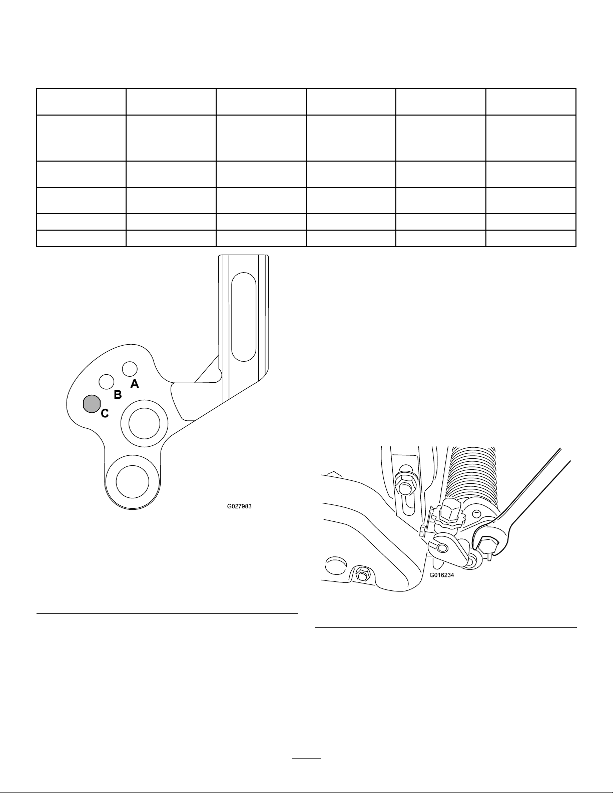
7.Ifyouarenotusingthegroomingmode,raise
thegroomingreelfromAtoBorfromBtoC.
Note:Athighergroomingheights,thegrooming
reelmayhavetobesetintheCposition,making
theraise/lowerfeatureunavailable.
TestingthePerformanceof
theGroomer
Important:Improperorover-aggressiveuseof
thegroomingreel(i.e.,toodeeportoofrequent
grooming)maycauseunnecessarystressonthe
turfleadingtoseveregreensdamage.Usethe
groomercautiously.
Itisimportanttodeterminetheperformanceof
thegroomerbeforeputtingitintoregularuseon
greens.Westronglysuggeststhatyouuseaformal
testprocedure.Thefollowingisapracticalwayof
determiningtheproperheight/depthsetting:
1.Setthecuttingreeltotheheight-of-cutthatyou
wouldnormallyusewithoutthegroomingreel.
UseaWiehlerollerandscraperforthefront
roller.
2.Setthegroomerreel1/2theheight-of-cutsetting
abovetheground(e.g.,for3.2mm(1/8inch)
height-of-cutsetting,setthegroomerat1.6mm
(1/16inch)abovetheground).
Note:Ifyouareusingthegroomerbrush,set
itattheheight-of-cutsettingabovetheground
(e.g.for3.2mm(1/8inch)height-of-cutsetting,
setthegroomerat3.2mm(1/8inch)abovethe
ground).
3.Makeapassoverthetestgreen,thenlower
thegroomerushwiththerollerlevelandmake
anotherpassoverthetestgreen.
Note:Ifyouareusingthegroomerbrush,
loweritto1/2theheight-of-cutsettingabovethe
ground(e.g.for3.2mm(1/8inch)height-of-cut
setting,setthegroomerat3.2mm(1/8inch)
abovetheground).
4.Comparetheresults.Therstgroomedarea
whenthesettingwas1/2theheight-of-cutsetting
abovethegroundwillhaveremovedsignicantly
lessgrassandthatchthanthesecondsetting.
Checkthetestgreen2or3daysaftertherst
groomingforgeneralcondition/damage.Ifthe
groomedareasareturningyellow/brown,and
thenon-groomedareasaregreen,thenthe
groomingwastooaggressive.
Note:Thecolorofthegrasswillchangewhen
youusethegroomingreel.Anexperienced
greenssuperintendentcanjudgebythecolor
oftheturf(alongwithcloseexamination)ifthe
currentgroomingpracticeisappropriateforthe
particulargreen.Becausethegroomingreel
standsupmoregrassandremovesthatch,the
qualityofthecutwillnotbethesameaswithout
thegroomer.Thiseffectismostnoticeablethe
rstfewtimesyouuseagroomeronagreen.
10