3
Installing the Springs
For Machines with Serial No.
403448001 and Before Only
Parts needed for this procedure:
2
Spring
Procedure
Use an approved T oro spring-compression tool to
remove and install springs of the strut assembly .
Contact your authorized T oro distributor .
1. Place the strut assembly into the compression
tool and use the tool to compress the spring.
2. While the spring is compressed, remove the
collar .
3. Remove the spring from the strut assembly
(Figure 1 ).
4. Install the new spring over the existing strut
assembly ( Figure 1 ).
5. Using the T oro spring-compression tool,
compress the spring.
6. While the spring is compressed, install the collar .
7. Carefully release pressure on the spring,
allowing it to seat on the collar .
8. Remove the strut assembly from the
compression tool.
Note: Repeat this procedure for the other side of the
machine.
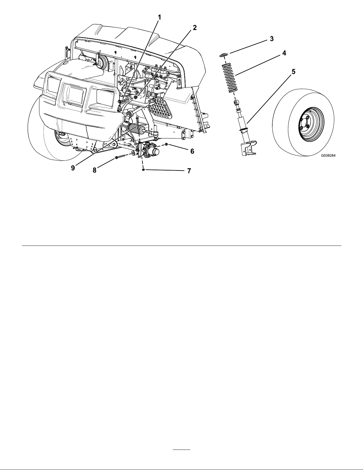
4
Installing the Strut
Assembly
For Machines with Serial No.
403448001 and Before Only
No Parts Required
Procedure
1. Install strut assembly to the machine.
2. Secure the upper portion of the strut assembly
to the frame using the upper , hex-head bolt (1/2
x 2-1/4 inches) and locknut (1/2 inch) as shown
in Figure 1 .
3. T orque the hex-head bolt (1/2 x 2-1/4 inches) to
91 to 1 13 N∙m (67 to 83 ft-lb).
4. Install the hex-head bolt (3/8 x 4-3/4 inches) and
ange nut (3/8 inch) to the spindle ( Figure 1 ).
5. T orque the hex-head bolt (3/8 x 4-3/4 inches) to
37 to 45 N∙m (27 to 33 ft-lb).
6. Secure the lower portion of the strut assembly
to the control arm using the hex-head bolt (3/8 x
3-1/2 inches) and ange nut (3/8 inch) as shown
in Figure 1 .
7. T orque the hex-head bolt (3/8 x 3-1/2 inches) to
37 to 45 N∙m (27 to 33 ft-lb).
8. Install the front wheel.
Note: Repeat this procedure for the other side of the
machine.
6