Toro 03638 User manual

FormNo.3420-472RevA
8-BladeRadialReel,8-Blade
ForwardSweptReel,or11-Blade
ForwardSweptReelDPACutting
Unitwith7inReel
Reelmaster®5010-HSeriesTractionUnit
ModelNo.03638—SerialNo.400000000andUp
ModelNo.03639—SerialNo.400000000andUp
ModelNo.03641—SerialNo.400000000andUp
Registeratwww.Toro.com.
OriginalInstructions(EN)*3420-472*A

WARNING
CALIFORNIA
Proposition65Warning
Thisproductcontainsachemical
orchemicalsknowntotheStateof
Californiatocausecancer,birthdefects,
orreproductiveharm.
ThisproductcomplieswithallrelevantEuropean
directives.Fordetails,pleaseseetheDeclarationof
Incorporation(DOI)atthebackofthispublication.
Introduction
Important:Tomaximizethesafety,performance,
andproperoperationofthismachine,carefully
readandfullyunderstandthecontentsofthis
Operator’sManual.Failingtofollowthese
operatinginstructionsortoreceiveproper
trainingmayresultininjury.Formoreinformation
onsafeoperatingpractices,includingsafetytips
andtrainingmaterials,gotowww.Toro.com.
Readthisinformationcarefullytolearnhowtooperate
andmaintainyourproductproperlyandtoavoid
injuryandproductdamage.Youareresponsiblefor
operatingtheproductproperlyandsafely.
YoumaycontactT orodirectlyatwww.Toro.com
forproductsafetyandoperationtrainingmaterials,
accessoryinformation,helpndingadealer,orto
registeryourproduct.
Wheneveryouneedservice,genuineToroparts,
oradditionalinformation,contactanathorizedToro
distributororT oroCustomerServiceandhavethe
modelandserialnumbersofyourproductready.
Figure1identiesthelocationofthemodelandserial
numbersontheproduct.Writethenumbersinthe
spaceprovided.
g027159
Figure1
1.Locationofthemodelandserialnumbers
ModelNo.
SerialNo.
©2017—TheToro®Company
8111LyndaleAvenueSouth
Bloomington,MN554202
Contactusatwww.Toro.com.
PrintedintheUSA
AllRightsReserved

Thismanualidentiespotentialhazardsandhas
safetymessagesidentiedbythesafety-alertsymbol
(Figure2),whichsignalsahazardthatmaycause
seriousinjuryordeathifyoudonotfollowthe
recommendedprecautions.
g000502
Figure2
1.Safety-alertsymbol
Thismanualuses2wordstohighlightinformation.
Importantcallsattentiontospecialmechanical
informationandNoteemphasizesgeneralinformation
worthyofspecialattention.
Contents
Safety.......................................................................3
SafetyandInstructionalDecals..........................4
Setup........................................................................5
1InspectingtheCuttingUnit...............................5
2UsingtheKickstand.........................................5
3AdjustingtheRearShield.................................6
4InstallingtheLooseParts.................................6
ProductOverview.....................................................8
Specications....................................................8
Attachments/Accessories...................................8
Operation..................................................................8
MakingAdjustments...........................................8
Height-of-CutChartTerms................................10
Maintenance...........................................................16
LubricatingtheCuttingUnits.............................16
Relief-GrindingtheReel...................................16
ServicingtheBedknife......................................17
ServicingtheBedbar........................................18
ServicingtheHDDualPointAdjusters
(DPA)............................................................20
ServicingtheRoller...........................................22
Safety
Thismachinehasbeendesignedinaccordancewith
ENISO5395:2013.
Improperuseormaintenanceofthisequipment
canresultininjuryordeath.Toreducethe
potentialforinjuryordeath,complywiththe
followingsafetyinstructions.
•Read,understand,andfollowallinstructionsinthis
Operator’sManualbeforeoperatingthecutting
unit.
•Lowerthecuttingunitstotheground,engagethe
parkingbrake,shutofftheengine,andremovethe
keyfromtheignitionswitchwheneveryouleave
themachineunattended.
•Besurethatthecuttingunitsareinsafeoperating
conditionbykeepingnuts,bolts,andscrewstight.
3

SafetyandInstructionalDecals
Safetydecalsandinstructionsareeasilyvisibletotheoperatorandarelocatednearanyarea
ofpotentialdanger.Replaceanydecalthatisdamagedormissing.
decal93-6688
93-6688
1.Warning—readthe
instructionsbefore
servicingorperforming
maintenance.
2.Cuttinghazardofhandor
foot—shutofftheengine
andwaitformovingparts
tostop.
4

Setup
LooseParts
Usethechartbelowtoverifythatallpartshavebeenshipped.
ProcedureDescriptionQty.Use
1Cuttingunit1Inspectthecuttingunit.
2Nopartsrequired–Usethekickstandwhentippingthe
cuttingunit.
3Nopartsrequired–Adjusttherearshield.
Straightgreasetting1
4O-ring1Installthelooseparts.
MediaandAdditionalParts
DescriptionQty.Use
Operator'sManual1
PartsCatalog(notincluded)—refertothe
includedpostcardforinformationonobtaining
thePartsCatalog
–Reviewthematerialandsaveitinanappropriateplace.
Note:Determinetheleftandrightsidesofthe
machinefromthenormaloperatingposition.
1
InspectingtheCuttingUnit
Partsneededforthisprocedure:
1Cuttingunit
Procedure
Afterthecuttingunitisremovedfromthebox,inspect
thefollowing:
1.Checkeachendofthereelforgrease.
Note:Greaseshouldbevisiblyevidentinthe
internalsplinesofthereelshaft.
2.Ensurethatallnutsandboltsaresecurely
tightened.
3.Makesurethatthecarrier-framesuspension
operatesfreelyanddoesnotbindwhenmoved
backandforth.
2
UsingtheKickstand
NoPartsRequired
Procedure
Wheneverthecuttingunithastobetippedtoexpose
thebedknife/reel,propuptherearofthecuttingunit
withthekickstand(suppliedwiththetractionunit)to
makesurethatthenutsonthebackendofthebedbar
adjustingscrewsarenotrestingontheworksurface
(Figure3).
5

g027160
Figure3
1.Kickstand
3
AdjustingtheRearShield
NoPartsRequired
Procedure
Undermostconditions,bestdispersionisattained
whentherearshieldisclosed(frontdischarge).When
conditionsareheavyorwet,therearshieldmaybe
opened.
Toopentherearshield(Figure4),loosenthecap
screwsecuringtheshieldtotheleftsideplate,rotate
theshieldtotheopenpositionandtightenthecap
screw.
g027161
Figure4
1.Capscrew2.Rearshield
4
InstallingtheLooseParts
Partsneededforthisprocedure:
1Straightgreasetting
1O-ring
Procedure
Thegreasettingmustbeinstalledonthereel-motor
sideofthecuttingunit.RefertoFigure5todetermine
thepositionofthereelmotors.
g031275
Figure5
1.Cuttingunit15.Cuttingunit5
2.Cuttingunit26.Reelmotor
3.Cuttingunit37.Weight
4.Cuttingunit4
1.Removeanddiscardthesetscrewonthe
reel-motorsideplate(Figure6).
g028640
Figure6
1.Capscrew(2)3.Greasetting
2.Setscrew4.Greasevent
6

ProductOverview
Specications
CuttingUnitWeight
0363854kg(118lb)
0363954kg(118lb)
0364155kg(121lb)
Attachments/Accessories
AselectionofToro-approvedattachmentsandaccessoriesisavailableforusewiththemachinetoenhance
andexpanditscapabilities.ContactyourAuthorizedServiceDealerorDistributororgotowww.Toro.comfor
alistofallapprovedattachmentsandaccessories
TobestprotectyourinvestmentandmaintainoptimalperformanceofyourToroequipment,countonT oro
genuineparts.Whenitcomestoreliability,Torodeliversreplacementpartsdesignedtotheexactengineering
specicationofourequipment.Forpeaceofmind,insistonTorogenuineparts.
Operation
Note:Determinetheleftandrightsidesofthe
machinefromthenormaloperatingposition.
MakingAdjustments
AdjustingtheBedknifetotheReel
Usethisproceduretosetthebedknifetothereeland
tochecktheconditionofthereelandbedknifeand
theirinteraction.Aftercompletingthisprocedure,
alwaystestthecuttingunitperformanceunderyour
eldconditions.Youmayneedtomakefurther
adjustmentstoobtainoptimalcuttingperformance.
Important:Donotovertightenthebedknifetothe
reeloryouwilldamageit.
•Afterbacklappingthecuttingunitorgrindingthe
reel,youmayneedtomowwiththecuttingunitfor
afewminutesandthenperformthisprocedure
toadjustthebedknifetothereelasthereeland
bedknifeadjusttoeachother.
•Youmayneedadditionaladjustmentsiftheturfis
extremelydenseoryourcuttingheightisverylow.
Youwillneedthefollowingtoolstocompletethis
procedure:
•Shim0.05mm(0.002inch)
•Cuttingperformancepaper
1.Positionthecuttingunitonaat,levelwork
surface.
2.Turnthebedbar-adjustingscrews
counterclockwisetoensurethatthebedbardoes
notcontactthereel(Figure8).
g019940
Figure8
1.Bedbar-adjustingscrew
3.Tipthecuttingunittoexposethebedknifeand
reel.
Important:Makesurethatthenutsonthe
backendofthebedbar-adjustingscrewsare
notrestingontheworksurface(Figure9).
g027160
Figure9
1.Kickstand
8

4.Rotatethereelsothatabladecrossesthe
bedknifeapproximately25mm(1inch)infrom
theendofthebedknifeontherightsideofthe
cuttingunit.
Note:Putanidentifyingmarkonthisbladeto
makesubsequentadjustmentseasier.
5.Insertthe0.05mm(0.002inch)shimbetween
themarkedreelbladeandthebedknifeatthe
pointwherethebladecrossesthebedknife.
6.Turntherightbedbaradjusterclockwiseuntil
youfeellightpressure(i.e.drag)ontheshim,
thenbackoffthebedbaradjuster2clicksand
removetheshim.
Note:Adjusting1sideofthecuttingunitaffects
theotherside,the2clickswillprovideclearance
forwhentheothersideisadjusted.
Note:Ifstartingwithalargegap,bothsides
shouldinitiallybedrawncloserbyalternately
tighteningtherightandlefthandsides.
7.Slowlyrotatethereelsothatthesameblade
thatyoucheckedontherightsideiscrossing
thebedknifeapproximately25mm(1inch)in
fromtheendofthebedknifeontheleftsideof
thecuttingunit.
8.Turntheleftbedbaradjusterclockwiseuntilthe
shimcanbeslidthroughthereeltobedknife
gapwithlightdrag.
9.Returntotherightsideandadjustasnecessary
togetlightdragontheshimbetweenthesame
bladeandbedknife.
10.Repeatsteps8and9untiltheshimcanbeslid
throughbothgapswithslightdrag,butoneclick
inonbothsidespreventstheshimfrompassing
throughonbothsides.
Note:Thebedknifeisnowparalleltothereel.
Note:Thisprocedureshouldnotbeneeded
ondailyadjustments,butshouldbedoneafter
grindingordisassembly.
11.Fromthisposition(i.e.,1clickinandshimnot
passingthrough)turnthebedbaradjusters
clockwise1clickeach.
Note:Eachclickturnedmovesthebedknife
0.022mm(0.0009inch).Donotovertighten
theadjustingscrews.
12.Testthecuttingperformancebyinsertingalong
stripofTorocuttingperformancepaperbetween
reelandbedknife,perpendiculartothebedknife
(Figure10).
Note:Slowlyrotatethereelforward;itshould
cutthepaper.
g027166
Figure10
Note:Ifexcessivereeldragoccurseither
backlaporgrindthecuttingunittoachievethe
sharpedgesneededforprecisioncutting.
AdjustingtheRearRoller
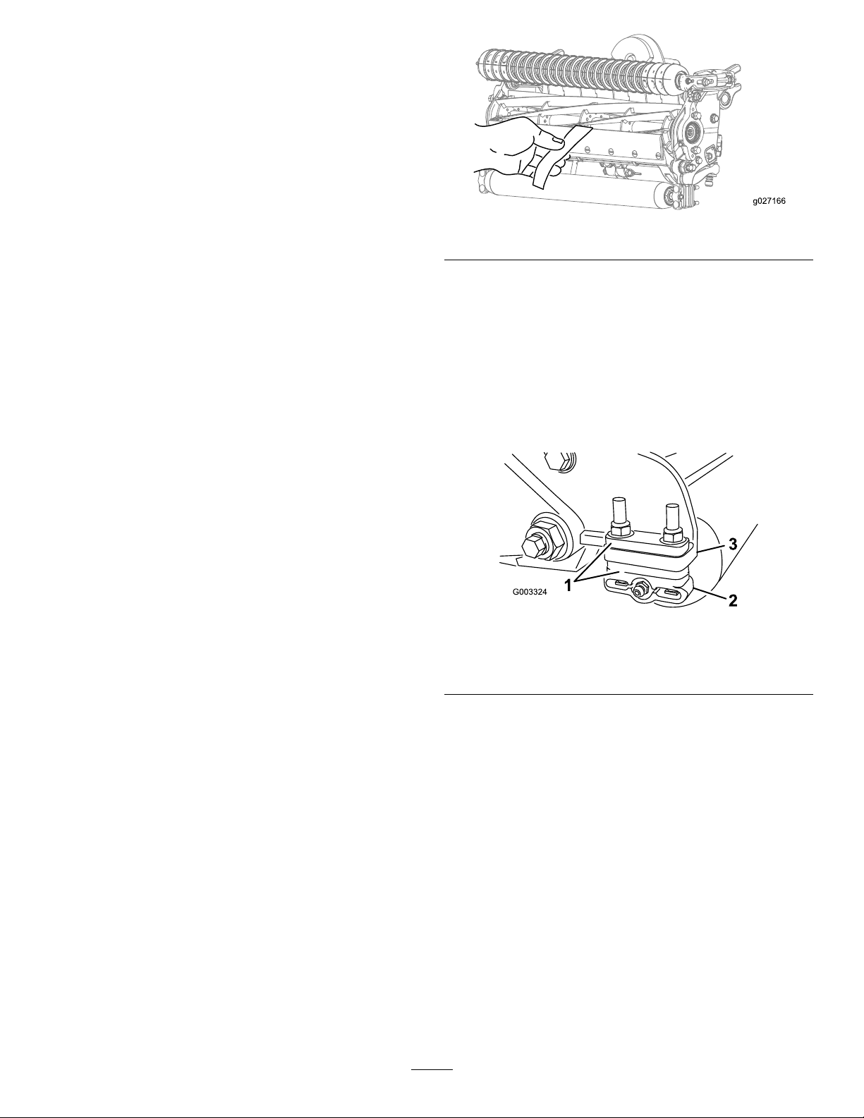
1.Adjusttherearrollerbrackets(Figure11)tothe
desiredheight-of-cutrangebypositioningthe
requiredamountofspacersbelowtheside-plate
mountingange(Figure11)pertheHOCChart.
g003324
Figure11
1.Spacer3.Side-platemountingange
2.Rollerbracket
2.Raisetherearofthecuttingunitandplacea
blockunderthebedknife.
3.Removethe2nutssecuringeachrollerbracket
andthespacertoeachside-platemounting
ange.
4.Lowertherollerandthescrewsfromthe
side-platemountingangesandspacers.
5.Placethespacersontothescrewsontheroller
brackets.
6.Re-securetherollerbracketandthespacersto
undersideoftheside-platemountinganges
withthenutspreviouslyremoved.
7.Verifythatthebedknife-to-reelcontactiscorrect.
Tipthemowertoexposethefrontandrear
rollersandthebedknife.
Note:Thepositionoftherearrollertothereel
iscontrolledbythemachiningtolerancesofthe
9

assembledcomponents,andsoparallelingis
notrequired.Alimitedamountofadjustmentis
possiblebysettingthecuttingunitonasurface
plateandlooseningtheside-platemountingcap
screws(Figure12).
g027167
Figure12
1.Side-platemountingcapscrews
8.Adjustandtightenthecapscrewsandtorque
thecapscrewsto37to45N∙m(27to33ft-lb).
Height-of-CutChartTerms
Height-of-CutSetting(HOC)
Thiscorrespondstothedesiredheightofcut.
BenchSetHeight-of-Cut
Thebenchsetheightofcutistheheightatwhich
thetopedgeofthebedknifeissetaboveaatlevel
surfacethatcontactsthebottomofboththefrontroller
andrearroller.
EffectiveHeightofCut
Thisistheactualheightthatthegrasshasbeen
cut.Foragivenbenchsetheight-of-cut,theactual
height-of-cutwillvarydependingonthetypeofgrass,
timeofyear,turf,andsoilconditions.Thecutting
unitsetup(aggressivenessofcut,rollers,bedknives,
attachmentsinstalled,turfcompensationsettings,
etc.)willalsoaffecttheeffectiveheightofcut.Check
theeffectiveheightofcutusingtheTurfEvaluator
(Model04399)regularlytodeterminethedesired
benchsetheightofcut.
AggressivenessofCut
Theaggressivenessofcuthasasignicantimpacton
theperformanceofthecuttingunit.Aggressiveness
ofcutreferstotheangleofthebedkniferelativetothe
ground(Figure13).
Thebestcuttingunitsetupisdependentonyour
turfconditionsanddesiredresults.Experiencewith
thecuttingunitonyourturfwilldeterminethebest
settingtouse.Aggressivenessofcutmaybeadjusted
throughoutthecuttingseasontoallowforvariousturf
conditions.
Ingeneral,lesstonormalaggressivesettings
aremoreappropriateforwarm-seasongrasses
(Bermuda,paspalum,zoysia)whilecool-season
grasses(bent,bluegrass,rye)mayrequirenormalto
moreaggressivesetups.Moreaggressivesetupscut
moregrassoffbyallowingthespinningreeltopull
moregrassupintothebedknife.
g033976
Figure13
1.Rearspacers3.Aggressivenessofcut
2.Side-platemountingange
RearSpacers
Thenumberofrearspacersdeterminesthe
aggressivenessofcutforthecuttingunit.Foragiven
heightofcut,addingspacersbelowtheside-plate
mountingangeincreasestheaggressivenessofthe
cuttingunit.Allcuttingunitsonagivenmachinemust
besettothesameaggressivenessofcut(number
ofrearspacers,ToroPartNo.106-3925);otherwise,
theafter-cutappearancecouldbenegativelyaffected
(Figure13).
ChainLinks
Thelocationatwhichthelift-armchainisattached
determinesthepitchangleoftherearroller(Figure
14).
10

g027170
Figure14
1.Liftchain3.Bottomhole
2.U-backet
Groomer
Thesearetherecommendedheight-of-cutsettings
whenagroomerkitisinstalledonthecuttingunit.
11

Height-of-CutChart
Thesearetherecommendedheight-of-cutsettingswhenagroomerkitisinstalledonthecuttingunit.
HOCSettingAggressivenessofCutNo.ofRearSpacersNo.ofChainLinksWithGroomerkits
installed**
0.64cm(0.250inch)Less
Normal
More
0
0
1
5
5
5
Y
Y
-
0.95cm(0.375inch)Less
Normal
More
0
1
2
5
5
5
Y
Y
-
1.27cm(0.500inch)Less
Normal
More
0
1
2
5
5
5
Y
Y
Y
1.56cm(0.625inch)Less
Normal
More
1
2
3
5
5
5
Y
Y
-
1.91cm(0.750inch)Less
Normal
More
2
3
4
5
5
5
Y
Y
-
2.22cm(0.875inch)Less
Normal
More
2
3
4
5
5
5
Y
Y
-
2.54cm(1.000inch)Less
Normal
More
3
4
5
5
5
4+
Y
Y
-
2.86cm(1.125inches)Less
Normal
More
4
5
6
5
5
5
-
-
-
3.18cm(1.250
inches)*+
Less
Normal
More
4
5
6
5
5
5
-
-
-
3.49cm(1.375
inches)*+
Less
Normal
More
4
5
6
5
5
5
-
-
-
3.81cm(1.500
inches)*+
Less
Normal
More
5
6
7
5
5
5
-
-
-
4.13cm(1.625
inches)*+
Less
Normal
More
6
7
8
4
4
4
-
-
-
4.44cm(1.750
inches)*+
Less
Normal
More
6
7
8
4
4
5
-
-
-
4.76cm(1.875
inches)*+
Less
Normal
More
7
8
9
4
5
5
-
-
-
5.08cm(2.000
inches)*+
Less
Normal
More
7
8
9
5
5
5
-
-
-
+IndicatesthattheU-bracket,ontheliftarm,ispositionedinthebottomhole(Figure14).
*TheHighHOCKit(PartNo.137-0890)mustbeinstalled.PositiontheHOCbracketinthetopside-platehole.
**YindicatesthatthiscombinationofHOCandspacerscanbeusedwithgroomers.
Note:Changing1chainlinkchangesthepitch-anglemovementoftherearrollerby4.5degrees.
Note:ChangingtheU-bracketontheliftarmtothebottomholeadds2.3degreestothepitchangleofthe
rearroller.
12

AdjustingtheHeightofCut(HOC)
Note:Forheightsofcutgreaterthan2.54cm(1.00
inch)theHighHeight-of-CutKitmustbeinstalled.
1.Loosenthelocknutssecuringtheheight-of-cut
armstothecutting-unitsideplates(Figure15).
g027171
Figure15
1.Adjustingscrew3.Height-of-cutarm
2.Locknut
2.Loosenthenutonthegaugebar(Figure16)
andsettheadjustingscrewtothedesiredheight
ofcut.
g003327
Figure16
1.Gaugebar4.Holesusedforsetting
groomerHOC
2.Heightadjustingscrew5.Holenotused
3.Nut
3.Measurethedistancebetweenthebottomofthe
screwheadandthefaceofthebartogetthe
heightofcut.
4.Hookthescrewheadonthecuttingedgeofthe
bedknifeandresttherearendofthebaronthe
rearroller(Figure17).
Note:ForcheckingtheHOConcuttingunits
installedwithshoulderrollers,placethegauge
baronthelargerdiametershouldersonthe
endsoftheshoulderroller.
5.Rotatetheadjustingscrewuntilthefrontroller
contactsthegaugebar(Figure17).
g027172
Figure17
6.Adjustbothendsoftherolleruntiltheentire
rollerisparalleltothebedknife.
Important:Whensetproperly,therear
andfrontrollerswillcontactthegauge
barandthescrewwillbesnugagainstthe
bedknife.Thisensuresthattheheightofcut
isidenticalatbothendsofthebedknife.
7.Tightenthenutstosecuretheadjustment.
Note:Donotovertightenthenuts.Tightenthem
justenoughtoremoveplayfromthewasher.
13

Usethefollowingcharttodeterminewhichbedknifeisbestsuitedforthedesiredheightofcut.
Bedknife/HeightofCutChart
BedknifePartNo.BedknifeLipHeightHeightofCut
LowHOC(Optional)110-40845.6mm
(0.220inch)
6.4to12.7mm
(0.250to0.500inch)
EdgeMax®LowHOC
(Model03641)
137-08325.6mm
(0.220inch)
6.4to-12.7mm
(0.250to0.500inch)
ExtendedLowHOC
(Optional)
120-16405.6mm
(0.220inch)
6.4to12.7mm
(0.250to0.500inch)
ExtendedEdgeMax®Low
HOC(Optional)
119-42805.6mm
(0.220inch)
6.4to12.7mm
(0.250to0.500inch)
EdgeMax®
(Models03638and03639)
137-08336.9mm
(0.270inch)
9.5to38.1mm
(0.375to1.50inches)*
Standard(Optional)108-90966.9mm
(0.270inch)
9.5to38.1mm
(0.375to1.50inches)*
HeavyDuty(Optional)110-40749.3mm
(0.370inch)
12.7to38.1mm
(0.500to1.50inches)
*Warm-seasongrassesmayrequiretheLowHOCbedknifefor12.7mm(0.500inch)andbelow.
g006510
Figure18
1.Bedknifelipheight
AdjustingtheTurf-Compensation
Settings
Theturf-compensationspringtransferstheweight
fromthefronttotherearroller.Thishelpstoreduce
awavepatternintheturf,alsoknownasmarcelling
orbobbing.
Important:Makethespringadjustmentswiththe
cuttingunitmountedtothetractionunit,pointing
straightaheadandloweredtotheshopoor.
1.Makesurethatthehairpincotterisinstalledin
therearholeinthespringrod(Figure19).
g027169
Figure19
1.Turf-compensationspring3.Springrod
2.Hairpincotter4.Hexnuts
2.Tightenthehexnutsonthefrontendofthe
springroduntilthecompressedlengthofthe
springis15.9cm(6.25inches)(Figure19).
Note:Whenoperatingthemachineonrough
terrain,decreasethespringlengthby12.7mm
(1/2inch).
Note:Theturf-compensationsettingwill
needtoberesetiftheHOCsettingorthe
aggressiveness-of-cutsettingischanged.
14

CheckingandAdjustingthe
CuttingUnit
Thedualknobbedknife-to-reeladjustmentsystem
incorporatedinthiscuttingunitsimpliesthe
adjustmentprocedureneededtodeliveroptimum
mowingperformance.Thepreciseadjustment
possiblewiththedualknob/bedbardesigngives
thenecessarycontroltoprovideacontinual
self-sharpeningaction-thusmaintainingsharpcutting
edges,ensuringgoodqualityofcut,andgreatly
reducingtheneedforroutinebacklapping.
Priortomowingeachday,orasrequired,checkeach
cuttingunittoverifyproperbedknife-to-reelcontact.
Thismustbeperformedeventhoughthequality
ofcutisacceptable.
1.Slowlyrotatethereelinareversedirection,
listeningforreel-to-bedknifecontact.
Note:Theadjustmentknobshavedetents
correspondingto0.018mm(0.0007inch)
bedknifemovementforeachindexedposition.
RefertoAdjustingtheBedknifetotheReel
(page8).
2.Testthecuttingperformancebyinsertinga
longstripofcuttingperformancepaper(T oro
Part125-5610)betweenreelandbedknife,
perpendiculartothebedknife(Figure20).Slowly
rotatethereelforward;itshouldcutthepaper.
g027166
Figure20
Note:Ifexcessivecontact/reeldragisevident
itwillbeeithernecessarytobacklap,refacethe
frontofthebedknife,orgrindthecuttingunitto
achievethesharpedgesneededforprecision
cutting(refertotheT oroManualforSharpening
ReelandRotaryMowers,FormNo.09168SL).
Important:Lightcontactispreferred
atalltimes.Ifyoudonotmaintainlight
contact,thebedknifeandreeledgeswill
notsufcientlyself-sharpenandwilldull
afteraperiodofoperation.Ifyoumaintain
excessivecontact,thebedknifeandreelwill
wearquicker,wearunevenly,andthequality
ofcutmaybeadverselyaffected.
Note:Afterextendedrunning,aridgewill
eventuallydevelopatbothendsofthebedknife.
Roundofforlethesenotchesushwiththe
cuttingedgeofthebedknifetoensuresmooth
operation.
Note:Overtime,youwillneedtogrindthe
chamfer(Figure21),asitisonlydesignedtolast
40%ofthebedknifelife.
g031270
Figure21
1.Lead-inchamferonright
endofbedknife
3.1.5mm(0.060inch)
2.6mm(0.25inch)
Note:Donotmakethelead-inchamfertoo
largeasitmaycauseturftufting.
15

Maintenance
LubricatingtheCutting
Units
Eachcuttingunithas5greasettings(Figure22)that
mustbelubricatedregularlywithNo.2lithiumgrease.
Thereare2lubricationpointsonthefrontroller,rear
roller,and1atthereelmotorspline.
Note:Lubricatingcuttingunitsimmediatelyafter
washinghelpspurgewateroutofthebearings
andincreasesbearinglife.
1.Wipeeachgreasettingwithacleanrag.
2.Applygreaseuntilcleangreasecomesoutof
therollersealsandthebearingreliefvalve.
3.Wipeanyexcessgreaseaway.
g027174
Figure22
Greasettinglocationsonthereelmotorside.
Relief-GrindingtheReel
Thenewreelhasalandwidthof1.3to1.5mm(0.050
to0.060inch)anda30degreereliefgrind.
Whenthelandwidthgetslargerthan3mm(0.120
inch)wide,dothefollowing:
1.Applya30degreereliefgrindonallreelblades
untilthelandwidthis1.3mm(0.050inch)wide
(Figure23andFigure24).
g028800
Figure23
Model03638
1.30degrees2.1.3mm(0.050inch)
g028838
Figure24
Models03639and03641
1.1.3mm(0.050inch)2.30degrees
2.Spingrindthereeltoachieve<0.025mm(0.001
inch)reelrun-out.
Note:Thiscausesthelandwidthtogrow
slightly.
Note:Toextendthelongevityofthesharpnessofthe
edgeofthereelandthebedknife—aftergrindingthe
reeland/orthebedknife—checkthereeltobedknife
contactagainaftercutting2faiways,asanyburrs
willberemoved,whichmaycreateimproperreelto
bedknifeclearanceandthusacceleratewear.
16

ServicingtheBedknife
Thebedknifeservicelimitsarelistedinthefollowingchart.
Important:Operatingthecuttingunitwiththebedknifebelowtheservicelimitmayresultinpoor
after-cutappearanceandreducethestructuralintegrityofthebedknifeforimpacts.
BedknifeServiceLimitChart
BedknifePartBedknifeLipHeight*ServiceLimit*GrindAngles
Top/FrontAngles
EdgeMax®LowHOC
(Model03641)
137-08325.6mm
(0.220inch)
6.4-12.7mm
(0.250-0.500inch)10/5Degrees
LowHOC(Optional)110-40845.6mm
(0.220inch)
4.8mm
(0.190inch)10/5Degrees
ExtendedEdgeMax®
LowHOC(Optional)
119-42805.6mm
(0.220inch)
4.8mm
(0.190inch)10/10Degrees
ExtendedLowHOC
(Optional)
120-16405.6mm
(0.220inch)
4.8mm
(0.190inch)10/10Degrees
EdgeMax®
(Models03638and
03639)
137-08336.9mm
(0.270inch)
4.8mm
(0.190inch)10/5Degrees
Standard(Optional)108-90966.9mm
(0.270inch)
4.8mm
(0.190inch)10/5Degrees
HeavyDuty(Optional)110-40749.3mm
(0.370inch)
4.8mm
(0.190inch)10/5Degrees
RecommendedTopandFrontBedknifeGrind
Angles(Figure25)
g027268
Figure25
1.Bedknifeservicelimit*
2.Topgrindangle
3.Frontgrindangle
Note:Allbedknifeservicelimitmeasurements
referencethebottomofthebedknife(Figure26)
g007165
Figure26
CheckingtheTopGrindAngle
Theanglethatyouusetogrindyourbedknivesis
veryimportant.
Usetheangleindicator(T oroPartNo.131-6828)and
theangle-indicatormount(ToroPartNo.131-6829)to
checktheanglethatyourgrinderproducesandthen
correctforanygrinderinaccuracy.
1.Placetheangleindicatoronthebottomsideof
thebedknifeasshowninFigure27.
17

g034113
Figure27
1.Bedknife(vertical)2.Angleindicator
2.PresstheAltZerobuttonontheangleindicator.
3.Placetheangle-indicatormountontheedge
ofthebedknifesothattheedgeofthemagnet
mateswiththeedgeofthebedknife(Figure28).
Note:Thedigitaldisplayshouldbevisiblefrom
thesamesideduringthisstepasitwasinstep1.
g034114
Figure28
1.Angle-indicatormount3.Bedknife
2.Edgeofthemagnetmated
withtheedgeofthe
bedknife
4.Angleindicator
4.Placetheangleindicatoronthemountasshown
inFigure28.
Note:Thisistheanglethatyourgrinder
produces,andshouldbewithin2degreesofthe
recommendedtopgrindangle.
ServicingtheBedbar
RemovingtheBedbar
1.Turnthebedbar-adjustingscrews
counterclockwisetobackthebedknife
awayfromthereel(Figure29).
g006498
Figure29
1.Bedbar-adjustingscrew3.Bedbar
2.Spring-tensionnut4.Washer
2.Backoutthespring-tensionnut,untilthewasher
isnolongertensionedagainstthebedbar
(Figure29).
3.Oneachsideofthemachine,loosenthelocknut
securingthebedbarbolt(Figure30).
g003334
Figure30
1.Bedbarbolt2.Locknut
4.Removeeachbedbarboltallowingbedbarto
bepulleddownwardandremovedfromthe
machinebolt(Figure30).
Note:Accountfor2nylonand1stampedsteel
washeroneachendofthebedbar(Figure31).
18

g027176
Figure31
1.Bedbarbolt3.Steelwasher
2.Nut4.Nylonwasher
AssemblingtheBedbar
1.Installthebedbar,positioningthemountingears
betweenthewasherandbedbaradjuster.
2.Securethebedbartoeachsideplatewiththe
bedbarbolts(nutsonbolts)andthe6washers.
Note:Positionanylonwasheroneachside
oftheside-plateboss.Placeasteelwasher
outsideeachofthenylonwashers(Figure31).
3.Torquethebedbarboltsto37to45N∙m(27to
33ft-lb).
Note:Tightenthelocknutsuntiltheoutside
steelwasherstopsrotatingandtheendplayis
removedbut,donotovertightenordeectthe
sideplates.Washersontheinsidemayhavea
gap.
4.Tightenthespringtensionnutuntilthespringis
collapsed,thenbackoff1/2turn(Figure32).
g006505
Figure32
1.Springtensionnut2.Spring
19

ServicingtheHDDualPoint
Adjusters(DPA)
1.Removeallparts(refertotheInstallation
InstructionsfortheHDDPAKitandtoFigure
33).
2.Applyanti-seizecompoundtotheinsideof
thebushingareaoncuttingunitcenterframe
(Figure33).
3.Alignthekeysonangebushingstotheslotsin
theframeandinstallthebushings(Figure33).
4.Installawavewasherontotheadjustershaftand
slidetheadjustershaftintotheangebushings
intheframeofthecuttingunit(Figure33).
5.Securetheadjustershaftwithaatwasherand
locknut(Figure33).
6.T orquethelocknutto20to27N∙m(15to20
ft-lb).
Note:Thebedbaradjustershafthasleft-hand
threads.
g016926
Figure33
1.Shaftadjuster4.Applyanti-seizecompound
here.
7.Applyanti-seizecompound
here.
10.Compressionspring
2.Wavewasher5.Flatwasher8.Bedbar-adjusterscrew11.Spring-tensionnut
3.Flangebushing6.Locknut9.Hardenedwasher
7.Applyanti-seizecompoundtothethreadsofthe
bedbar-adjusterscrewthattintotheadjuster
shaft.
8.Threadthebedbar-adjusterscrewintothe
adjustershaft.
9.Looselyinstallthehardenedwasher,spring,and
springtensionnutontotheadjusterscrew.
10.Installthebedbar,positioningthemountingears
betweenthewasherandthebedbaradjuster.
11.Securethebedbartoeachsideplatewiththe
bedbarbolts(nutsonbolts)and6washers.
Note:Positionanylonwasheroneachsideof
theside-plateboss.
12.Placeasteelwasheroutsideeachofthenylon
washers(Figure33).
13.Torquethebedbarboltsto37to45N∙m(27to
33ft-lb).
14.Tightenthelocknutsuntiltheoutsidesteel
washerstopsrotatingandendplayisremoved
butdonotovertightenordeectthesideplates.
Note:Washersontheinsidemayhaveagap
(Figure33).
15.Tightenthenutoneachbedbar-adjuster
assemblyuntilthecompressionspringisfully
compressed,thenloosenthenut1/2turn(Figure
33).
20
Other manuals for 03638
1
This manual suits for next models
2
Table of contents
Other Toro Lawn Mower Accessories manuals

Toro
Toro 08838 User manual

Toro
Toro Greensmaster TriFlex 3300 Series User manual

Toro
Toro Groundsmaster e3200 User manual

Toro
Toro 04553 User manual

Toro
Toro Flex-Force Power System 51810T User manual

Toro
Toro 30832 User manual

Toro
Toro 04294 User manual

Toro
Toro 117-9449 User manual

Toro
Toro Groundsmaster 4500 Series User manual

Toro
Toro 30506 User manual