manuals.online logo
Brands
  1. Home
  2. •
  3. Brands
  4. •
  5. Toshiba
  6. •
  7. Copier
  8. •
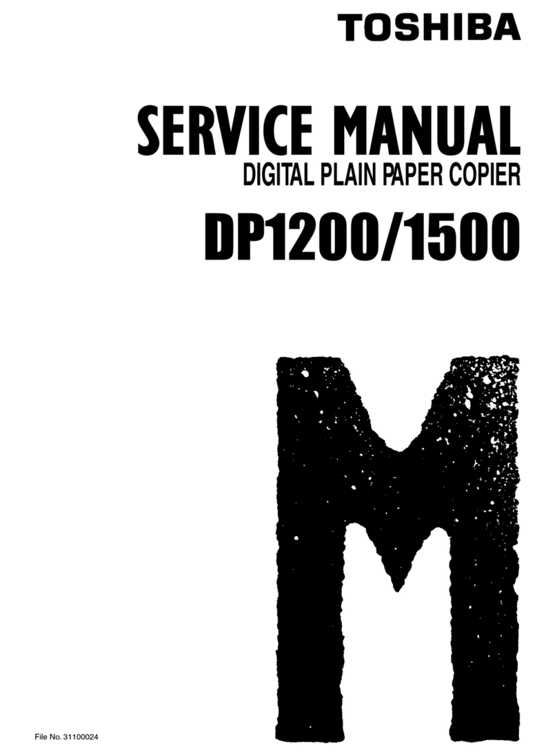
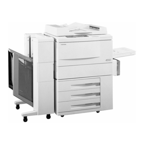
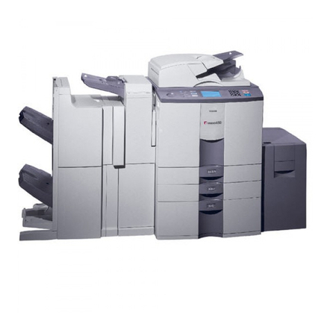
  9. Toshiba 4550 User manual

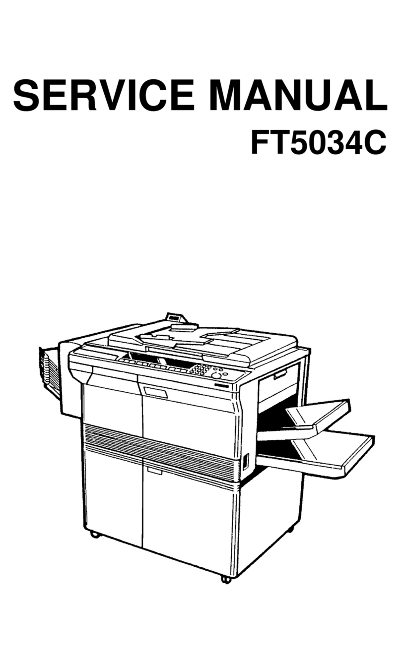
Toshiba 4550 User manual

Toshiba 4550
Service Manual
Service Handbook
www.electronicsrepair.net
[4550 SERVICE MANUAL] 2510001 1
GENERAL PRECAUTIONS REGARDING THE INSTALLATION AND 2510001 1
THE SERVICE OF THE COPIERS..................................................0-1 2510001 1
1. SPECIFICATIONS, ACCESSORIES, OPTIONS....................................1-1 4550101 2
1.1 Specifications........................................................1-1 4550101 0
1.2 Accessories...........................................................1-4 4550104 0
1.3 Options...............................................................1-4 4550104 0
1.4 System List...........................................................1-5 4550105 0
2. GENERAL DESCRIPTION OF THE 4550.........................................2-1 4550201 2
2.1 Functions of the 4550.................................................2-1 4550201 0
2.2 Front/Rear View.......................................................2-3 4550203 0
2.2.1 Front Section View.................................................2-3 4550203 0
2.2.2 Rear Side View.....................................................2-4 4550204 0
2.2.3 ADF Front Section View.............................................2-5 4550205 0
2.3 Electrical Parts Layout...............................................2-6 4550206 0
2.3.1 Copier's DC Electrical Parts.......................................2-6 4550206 0
2.3.1.1 DC Electrical Parts Except Motors...............................2-6 4550206 0
2.3.1.2 Motors..........................................................2-7 2510206 0
2.3.2 AC Electrical Parts................................................2-8 4550207 0
2.3.3 ADF Electrical Parts...............................................2-9 4550209 0
2.4 Symbols and Functions of Electrical Parts............................2-10 4550210 0
2.5 Wire-Harness Location Diagram........................................2-16 4550216 0
2.5.1 Location Diagram for Upper Unit...................................2-16 4550216 0
2.5.2 Location Diagram for Lower Unit...................................2-17 4550217 0
2.6 Removal of Covers and PC Boards......................................2-18 5010217 0
2.6.1 Removal for Covers................................................2-18 5010217 0
2.6.2 Removal of Main PC Boards.........................................2-22 4550222 0
3. COPYING PROCESS.........................................................3-1 2510301 2
3.1 Copying Process.......................................................3-1 2510301 0
3.2 Detailed Description of Copying Process...............................3-2 2510302 0
3.3 Comparison with the 4010 of Copying Process Conditions...............3-10 4550310 0
4. GENERAL COPIER OPERATION................................................4-1 4010401 2
4.1 Operation Outline.....................................................4-1 4010401 0
4.2 Descriptions of Operation.............................................4-1 4010401 0
4.2.1 Operation up to Standby State after Power On.......................4-1 4010401 0
4.2.2 Standby (Ready)....................................................4-1 4010401 0
4.2.3 Automatic Feed Copying Using the PRINT Key.........................4-2 4010402 0
4.2.4 Bypass-Feed Copying................................................4-5 2510405 0
4.2.5 Interrupt Copying..................................................4-5 2510405 0
4.3 Fault Detection.......................................................4-6 2510406 0
4.4 Flow Charts..........................................................4-13 2510413 0
4.4.1 Power On to Ready.................................................4-13 2510413 0
4.4.2 Automatic Cassette Feed Copying...................................4-15 4010415 0
5. DISPLAY UNIT............................................................5-1 4550501 2
5.1 Detailed Drawing of the Control Panel and the Display Panel...........5-1 4550501 0
5.2 Items Shown on the Display Panel......................................5-2 4550502 0
5.2.1 Display during Normal Copying......................................5-2 4550502 0
5.2.2 Displays in the Event of Faulty Conditions.........................5-3 4550503 0
5.3 Relation between Copier Conditions and Operator's Actions.............5-6 4550506 0
5.4 Description of Operation..............................................5-7 4550507 0
5.4.1 Dot Matrix LCD Display Circuit.....................................5-7 4550507 0
5.4.2 LED Display Circuit................................................5-8 4550508 0
5.5 Disassembly and Replacement..........................................5-12 5010513 0
6. DRIVE SYSTEM............................................................6-1 4550601 2
6.1 Construction of Drive System..........................................6-1 4550601 0
6.2 Description of Operations.............................................6-1 4550601 0
6.3 Main Motor (IC Motor) Drive...........................................6-2 2510602 0
6.3.1 Structure of IC Motor..............................................6-2 2510602 0
6.3.2 IC Motor Rotation System...........................................6-2 2510602 0
6.3.3 Position-Detection of Rotor........................................6-3 2510603 0
6.3.4 Main Motor Drive...................................................6-4 2510604 0
6.3.5 Control Signals....................................................6-5 2510605 0
6.4 Disassembly and Replacement...........................................6-8 2510608 0
6.5 Adjustment...........................................................6-10 2510610 0
6.5.1 Drum and Heat Roller Speed Adjustment.............................6-10 2510610 0
7. OPTICAL SYSTEM..........................................................7-1 2510701 2
7.1 Functions.............................................................7-1 2510701 0
7.2 Construction..........................................................7-1 2510701 0
7.3 Description of Operation..............................................7-6 2510706 0
7.3.1 Scanning Motor (M2)................................................7-6 2510706 0
7.3.2 Mirror Motor (M4)/Lens Motor (M3)..................................7-6 2510706 0
7.3.3 Document Motor (M16)...............................................7-7 2510707 0
7.3.4 Optical Fan Motor (M11)............................................7-7 2510707 0
7.4 Pulse Motor Drive.....................................................7-8 2510708 0
7.4.1 Features...........................................................7-8 2510708 0
7.4.2 Principle of the Pulse Motor.......................................7-8 2510708 0
7.4.3 Pulse Motor Drive Circuit (Constant Current Type).................7-11 4550711 0
7.4.4 Pulse Motor Drive Circuit (Constant Voltage Type).................7-14 4550714 0
7.5 Exposure Control Circuit.............................................7-15 2510715 0
7.5.1 Brief Description.................................................7-15 2510715 0
7.5.2 Operation of Lamp Regulator.......................................7-16 2510716 0
7.5.3 Automatic Exposure Sensor Circuit.................................7-16 2510716 0
7.5.4 Arithmetic and Control Unit.......................................7-17 2510717 0
7.5.5 Lamp Regulator Circuit............................................7-19 2510719 0
7.6 Automatic Original-Size Detection Circuit............................7-20 2510720 0
7.6.1 Principle of Original-Size Detection..............................7-20 2510720 0
7.6.2 Original Size Detection...........................................7-20 2510720 0
7.7 Disassembly and Replacement..........................................7-23 2510723 0
7.8 Adjustment...........................................................7-36 4550736 0
7.8.1 Uneven Light Distribution.........................................7-36 4550736 0
7.8.2 Exposure Adjustment...............................................7-37 4010737 0
7.8.3 Adjustment of Carriage Drive Belt.................................7-43 2510747 0
7.8.4 Adjustment of Carriages 1 and 2...................................7-43 2510747 0
7.8.5 Adjustment of Mirrors and Lens....................................7-44 4550744 0
7.8.5.1 Adjustment of Focus and Horizontal Reproduction Ratio..........7-44 4550744 0
7.8.5.2 Optical Axis Adjustment........................................7-46 4550746 0
7.8.5.3 Image Distortion...............................................7-48 4550748 0
7.8.5.4 Image Inclination..............................................7-49 4550749 0
7.8.5.5 Side Deviation of Lens Unit....................................7-50 4550750 0
7.8.6 Installation of Red Filter........................................7-51 2510754 0
8. PAPER FEEDING SECTION...................................................8-1 2510801 2
8.1 Functions.............................................................8-1 2510801 0
8.2 Description of Operation..............................................8-3 2510803 0
8.2.1 Up-and-Down Movement of Manual Feed Roller.........................8-3 2510803 0
8.2.2 Up-and-Down Movement of Pick-Up Roller.............................8-4 2510804 0
8.2.3 LCC Pick-Up Roller.................................................8-4 2510804 0
8.2.4 Paper Feeding Operation............................................8-5 2510805 0
8.2.5 Paper Separation Function..........................................8-7 2510807 0
8.3 Motor Drive Circuit...................................................8-8 2510808 0
8.3.1 Brush Motor Drive Circuit..........................................8-8 2510808 0
8.3.2 Pulse Motor Drive Circuit (Constant Current Type)..................8-9 4550809 0
8.4 Disassembly and Replacement..........................................8-12 4550812 0
8.5 Adjustment...........................................................8-21 5010819 0
8.5.1 Positions for Paper-Size Switch Tabs..............................8-21 5010819 0
8.5.2 Height Adjustment of Pick-Up Roller and Manual Feed Roller........8-22 2510821 0
8.5.2.1 Height Adjustment of Pick-Up Roller............................8-22 2510821 0
8.5.2.2 Height Adjustment of Manual Feed Roller........................8-22 2510821 0
8.5.3 Adjustment of Drum/Heat Roller/Aligning Roller Speed, 4550823 0
Aligning Value, Registration, Leading Edge in Image Shift, 4550823 0
Leading Edge in Edge Erasing, Trailing Edge in Edge Erasing, 4550823 0
Editing Position, Leading-Edge Void and Trailing-Edge Void.......8-23 4550823 0
8.5.3.1 Operational Procedure..........................................8-24 4550824 0
8.5.3.2 Aligning Motor Speed Adjustment................................8-25 4550825 0
8.5.3.3 Aligning Value Adjustment......................................8-26 2510825 0
8.5.3.4 Registration Adjustment........................................8-27 2510826 0
8.5.3.5 Adjustment of Leading Edge in Image Shift......................8-28 4550828 0
8.5.3.6 Adjustment of Leading Edge and Trailing Edge in Edge Erasing...8-29 4550829 0
8.5.3.7 Adjustment of Leading-Edge Void and Trailing-Edge Void.........8-31 4550831 0
8.5.4 Side Deviation Adjustment.........................................8-32 2510827 0
8.5.4.1 Side Deviation in Manual Feeding...............................8-32 2510827 0
8.5.4.2 Side Deviation in Cassette Feeding.............................8-33 2510828 0
8.5.4.3 Side Deviation in LCC Feeding..................................8-34 2510829 0
8.5.4.4 Side Deviation in Pedestal Casette Feeding.....................8-35 2510830 0
8.5.5 Adjustment of LCC Separation Force................................8-36 2510831 0
8.5.5.1 Check of Separation Performance................................8-36 2510831 0
8.5.5.2 Adjustment of Separation Force.................................8-36 2510831 0
9. DRUM-RELATED SECTION....................................................9-1 2510901 2
9.1 Construction..........................................................9-1 2510901 0
9.2 Description of Functions..............................................9-2 2510902 0
9.3 Transfer, Separation Current Control Circuit..........................9-4 2510904 0
9.3.1 Outline............................................................9-4 2510904 0
9.3.2 Operation Explanation..............................................9-4 2510904 0
9.4 LED Eraser Array......................................................9-5 2510905 0
9.4.1 Outline............................................................9-5 2510905 0
9.4.2 Operation Description..............................................9-6 2510906 0
9.5 Control Circuit of Transfer/Separation Charger Wire Cleaning..........9-7 4550907 0
9.5.1 Description of Operation...........................................9-7 4550907 0
9.5.2 Motor Drive Circuit................................................9-8 4550908 0
9.6 Drum Temperature Detection Circuit....................................9-9 4550909 0
9.6.1 General Description................................................9-9 4550909 0
9.6.2 Circuit Description................................................9-9 4550909 0
9.7 Disassembly and Replacement..........................................9-11 4550911 0
9.8 Adjustment...........................................................9-20 4550920 0
9.8.1 Adjustment and Detection of Main Charger Output of High-Voltage 4550920 0
Transformer......................................................9-20 4550920 0
9.8.2 Adjustment and Detection of Transfer Output of High-Voltage 2510915 0
Transformer......................................................9-22 2510915 0
9.8.3 Adjustment and Detection of Separation Output of High-Voltage 2510916 0
Transformer......................................................9-23 2510916 0
9.8.3.1 Items to Check Before Adjustment...............................9-23 2510916 0
9.8.3.2 Output Adjustment Procedure....................................9-23 2510916 0
9.8.3.3 Output Detection Method........................................9-23 2510916 0
9.8.4 Adjustment and Detection of Developer Bias of High-Voltage 2510918 0
Transformer......................................................9-25 2510918 0
9.8.4.1 Output Adjustment Procedure....................................9-25 2510918 0
9.8.4.2 Output Detection Method........................................9-25 2510918 0
9.8.5 Editing Position Adjustment (Adjustment for Trimming and 2510920 0
Masking Copying).................................................9-27 2510920 0
10. DEVELOPER UNIT........................................................10-1 2511001 2
10.1 General Description.................................................10-1 2511001 0
10.2 Construction........................................................10-2 2511002 0
10.3 Developer Unit Drive................................................10-3 4551003 0
10.4 Brush Motor (Toner Motor (M15)) Drive Circuit.......................10-4 4551004 0
10.5 Auto-Toner Sensor Circuit...........................................10-5 2511005 0
10.5.1 Brief Description................................................10-5 2511005 0
10.5.2 Operation of Auto-Toner Sensor...................................10-6 2511006 0
10.6 Disassembly and Replacement.........................................10-8 4551008 0
10.7 Adjustment.........................................................10-15 2511015 0
10.7.1 Adjustment of Magnetic Brush (Leveler)..........................10-15 2511015 0
10.7.2 Adjustment of Developer-Pole Position...........................10-16 2511016 0
10.7.3 Auto-Toner Sensor Adjustment....................................10-17 2511017 0
11. CLEANER UNIT..........................................................11-1 2511101 2
11.1 Construction........................................................11-1 2511101 0
11.2 Description of Functions............................................11-3 2511103 0
11.3 Disassembly and Replacement.........................................11-4 2511104 0
12. FUSER UNIT/PAPER-EXIT UNIT............................................12-1 4551201 2
12.1 General Description.................................................12-1 4551201 0
12.2 Description of Operations...........................................12-2 2511202 0
12.3 Functions of Each Part..............................................12-2 2511202 0
12.4 Heater Control Circuit..............................................12-4 4011204 0
12.4.1 Temperature Detection Unit.......................................12-4 4011204 0
12.4.2 Detection of Thermistor Burnout..................................12-6 4551206 0
12.5 Disassembly and Replacement.........................................12-7 4551207 0
12.6 Adjustment.........................................................12-16 4551216 0
12.6.1 Heat Roller Pressure Adjustment.................................12-16 4551216 0
13. AUTOMATIC DUPLEXING DEVICE (ADD)......................................13-1 4551301 2
13.1 Introduction........................................................13-1 4551301 0
13.2 Construction........................................................13-2 4551302 0
13.2.1 Drive System.....................................................13-2 4551302 0
13.2.2 Driving of Exit/ADD Selection Gate...............................13-2 4551302 0
13.2.3 Driving of Stack Guides..........................................13-3 2511302 0
13.2.4 Driving of ADD Pick-Up Roller, ADD Feed Roller and 4551304 0
ADD Separation Roller...........................................13-4 4551304 0
13.2.5 Driving of ADD Aligning Roller...................................13-4 4551304 0
13.2.6 Driving of Transport Roller......................................13-4 4551304 0
13.3 Description of Operation............................................13-5 2511304 0
13.3.1 Paper Stacking Operation.........................................13-5 2511304 0
13.3.2 Duplexing (Re-Feeding) Operation.................................13-6 2511305 0
13.4 Motor Drive Circuit.................................................13-7 2511306 0
13.4.1 Brush Motor Drive Circuit........................................13-7 2511306 0
13.4.2 Pulse Motor Drive Circuit (Constant Current Type)................13-7 2511306 0
13.5 Disassembly and Replacement.........................................13-8 2511307 0
13.5.1 Stack Guide Unit.................................................13-8 2511307 0
13.5.2 Transport System................................................13-11 2511310 0
13.5.3 Drive System....................................................13-17 4551317 0
13.5.4 Switches........................................................13-21 4011320 0
13.6 Adjustment.........................................................13-24 2511322 0
13.6.1 Adjustment of Stack Guides......................................13-24 2511322 0
13.6.1.1 Installing the Stack Guide Unit..............................13-24 2511322 0
13.6.1.2 Adjusting the Stack Guide Unit in Position...................13-24 2511322 0
13.6.1.3 Adjusting ADD Side Deviation.................................13-25 2511323 0
13.6.2 Adjustment of ADD Pick-Up Roller Position.......................13-26 4551326 0
14. LARGE CAPACITY CASSETTE (LCC).........................................14-1 4551401 2
14.1 Introduction........................................................14-1 4551401 0
14.2 Construction and Drive Mechanism....................................14-2 4551402 0
14.3 Description of Operation............................................14-2 4551402 0
14.3.1 Paper-Empty Detection............................................14-2 4551402 0
14.3.2 Operation of Paper Feeding.......................................14-2 4551402 0
14.3.3 Operation of Elevator Tray.......................................14-2 4551402 0
14.4 Disassembly and Replacement.........................................14-4 2511403 0
14.5 Adjustment.........................................................14-10 4551410 0
14.5.1 Changing of Paper Size..........................................14-10 4551410 0
14.5.2 Fine Adjustment of Paper Guides.................................14-11 4551411 0
15. AUTOMATIC DOCUMENT FEEDER (ADF).......................................15-1 4551501 2
15.1 Introduction........................................................15-1 4551501 0
15.2 Construction........................................................15-2 4551502 0
15.3 Drive System Diagram (Rear View)....................................15-3 4551503 0
15.4 Explanation of Operation Sequence...................................15-4 4551504 0
15.4.1 Driving Directions of Rollers and Transport Belt.................15-4 4551504 0
15.4.2 Feeding/Exiting/Reversing of Originals...........................15-7 4551507 0
15.4.3 Description of Reversing Automatic Document Feeder (RADF) 4551511 0
Operation......................................................15-11 4551511 0
15.5 Block Diagram for Electrical Signals...............................15-13 4551513 0
15.6 Description of Interface Signals...................................15-14 4551514 0
15.6.1 Outline.........................................................15-14 4551514 0
15.6.2 Signals from the Copier to the ADF..............................15-14 4551514 0
15.6.3 Signals from the ADF to the Copier..............................15-15 4551515 0
15.7 Contents of Original Jams and ADF Errors...........................15-18 4551518 0
15.8 Detection of Original Sizes........................................15-20 4551520 0
15.9 Flow Charts........................................................15-22 4551522 0
15.9.1 Power ON up to Ready............................................15-22 4551522 0
15.9.2 Feeding Operation...............................................15-23 4551523 0
15.9.3 Pre-Feeding Operation...........................................15-27 4551527 0
15.9.4 Reverse Feeding.................................................15-28 4551528 0
15.9.5 Original Exiting................................................15-30 4551530 0
15.9.6 Original Jamming................................................15-31 4551531 0
15.10 Timing Charts.....................................................15-32 4551532 0
15.10.1 Single-Side Feed Mode (1 sheet, A4 size).......................15-32 4551532 0
15.10.2 Single-Side Feed Mode (3 sheets, A4 size)......................15-32 4551532 0
15.10.3 Single-Side Feed Mode (1 sheet, A3 size).......................15-33 4551533 0
15.10.4 Duplex Feed Mode (1 sheet, A3 size)............................15-33 4551533 0
15.10.5 Duplex Feed Mode (1 sheet, A4 size)............................15-34 4551534 0
15.11 Explanation of Circuit Operation..................................15-35 4551535 0
15.11.1 Power Circuit..................................................15-35 4551535 0
15.11.2 DC Motor Drive Circuit.........................................15-37 4551537 0
15.11.3 Shutter Solenoid Drive Circuit.................................15-39 4551539 0
15.12 Explanation of Input/Output Signals...............................15-41 4551541 0
15.12.1 DREQ Signal and DF-TXD Signal..................................15-41 4551541 0
15.12.2 DACK Signal and DF-RXD Signal..................................15-41 4551541 0
15.12.3 DCNT Signal....................................................15-41 4551541 0
15.12.4 Various Sensor Input Circuits..................................15-42 4551542 0
15.12.5 ADF Transport Motor Output Circuit.............................15-43 4551543 0
15.12.6 ADF Feed Motor Output Circuit..................................15-44 4551544 0
15.12.7 Clutch/Solenoid Output Circuit.................................15-45 4551545 0
15.12.8 ADF Cover Switch/ADF Set Switch................................15-45 4551545 0
15.13 Adjustment........................................................15-46 4551546 0
15.13.1 Independent Operation Mode (Test Mode).........................15-46 4551546 0
15.13.1.1 How to Use the Test Mode....................................15-46 4551546 0
15.13.2 Height Adjustment of Magnets...................................15-49 4551549 0
15.13.3 Adjustment of Separation Section...............................15-50 4551550 0
15.13.4 Adjustment of Flapper Solenoid.................................15-51 4551551 0
15.13.5 Adjustment of Original Skew....................................15-52 4551552 0
15.13.6 Registration Adjustment........................................15-53 4551553 0
15.14 Disassembly and Replacement.......................................15-54 4551554 0
15.14.1 Original Feed Tray.............................................15-54 4551554 0
15.14.2 Jam Access Cover...............................................15-54 4551554 0
15.14.3 ADF Cover......................................................15-54 4551554 0
15.14.4 ADF Maintenance Cover..........................................15-55 4551555 0
15.14.5 Configuration of the Original Feeding Drive (Reference)........15-55 4551555 0
15.14.6 ADF Feed Motor.................................................15-56 4551556 0
15.14.7 Weight Solenoid................................................15-57 4551557 0
15.14.8 Shutter Solenoid...............................................15-58 4551558 0
15.14.9 Separation Unit................................................15-59 4551559 0
15.14.10 ADF Pick-Up Roller/ADF Feed Roller............................15-60 4551560 0
15.14.11 ADF Clutch/ADF Aligning Roller................................15-62 4551562 0
15.14.12 ADF PC Board..................................................15-63 4551563 0
15.14.13 ADF Transport Motor...........................................15-63 4551563 0
15.14.14 ADF Exit Roller/Reversing Flapper.............................15-64 4551564 0
15.14.15 ADF Reversing Roller..........................................15-65 4551565 0
15.14.16 Transport Belt................................................15-66 4551566 0
15.14.17 ADF Unit......................................................15-68 4551568 0
15.15 Harness Location Diagram..........................................15-69 4551569 0
15.15.1 Harness Location Diagram (Feeding Section).....................15-69 4551569 0
15.15.2 Harness Location Diagram (Transport Motor Section).............15-70 4551570 0
15.15.3 Harness Location Diagram (Around PC Boards)....................15-71 4551571 0
16. POWER-STABILIZING CIRCUIT.............................................16-1 2511501 2
16.1 General Description.................................................16-1 2511501 0
16.2 Description of Operation............................................16-1 2511501 0
16.3 AC Wire-Harness Connection..........................................16-4 4011504 0
16.3.1 AC Wire-Harness Connection (110/115V)............................16-4 4011504 0
16.3.2 AC Wire-Harness Connection (200/220/240V)........................16-5 4011505 0
16.4 Transformer Circuit Diagram.........................................16-6 4011506 0
16.4.1 Power Transformer (110/115V).....................................16-6 4011506 0
16.4.2 Power Transformer (200/220/240V).................................16-7 4011507 0
16.4.3 High-Voltage Transformer for Main Charger (HVT-M)................16-8 2511508 0
16.4.4 High-Voltage Transformer for Transfer (HVT-T)....................16-9 4551609 0
16.4.5 Transfer Bias Transformer (PRE-TR)..............................16-10 2511510 0
16.4.6 ADF Power Transformer (ADF-TR)..................................16-11 2511511 0
16.5 Disassembly and Replacement........................................16-12 2511512 0
16.6 Adjustment.........................................................16-16 2511516 0
16.6.1 Adjustment of 24V DC Power Supply...............................16-16 2511516 0
19. JIGS AND SUPPLIES.....................................................19-1 4011801 2
19.1 List of Adjustment Jigs Used........................................19-1 4011801 0
19.2 TOSHIBA Supplies List...............................................19-2 2511802 0
19.3 Grease/Oil/Powder List..............................................19-4 2511804 0
19.4 Precautions for Storing and Handling Supplies.......................19-6 2511806 0
19.4.1 Precautions for Storing TOSHIBA Supplies.........................19-6 2511806 0
19.4.2 Inspecting and Cleaning OPC Drum.................................19-6 2511806 0
19.4.3 Checking Drum Cleaning Blade.....................................19-7 4011807 0
19.4.4 Checking and Replacing Cleaning Felt Roller......................19-8 4011808 0
19.4.5 Checking and Cleaning Upper and Lower Heat Rollers...............19-8 4011808 0
19.4.6 Checking and Cleaning Heat Roller Cleaning Blade.................19-8 4011808 0
20. ELECTRICAL CIRCUIT DIAGRAMS...........................................20-1 4552001 2
20.1 Control Block Diagram...............................................20-1 4552001 0
20.2 DC Wire-Harness Connection..........................................20-2 4552002 0
20.2.1 Copier DC Wire-Harness Connection................................20-2 4552002 0
20.2.2 ADF DC Wire-Harness Connection...................................20-3 4552003 0
20.3 Circuit Diagram.....................................................20-4 4552004 0

Other Toshiba Copier manuals

Toshiba e-STUDIO 452 User manual

Toshiba

Toshiba e-STUDIO 452 User manual

Toshiba DP1600 How to use

Toshiba

Toshiba DP1600 How to use

Toshiba e-STUDIO 2010AC User manual

Toshiba

Toshiba e-STUDIO 2010AC User manual

Toshiba GA-1120 User manual

Toshiba

Toshiba GA-1120 User manual

Toshiba 4560 User manual

Toshiba

Toshiba 4560 User manual

Toshiba e-studio 120 User manual

Toshiba

Toshiba e-studio 120 User manual

Toshiba 60th Series User manual

Toshiba

Toshiba 60th Series User manual

Toshiba 65/5560 How to use

Toshiba

Toshiba 65/5560 How to use

Toshiba MR-3011 User manual

Toshiba

Toshiba MR-3011 User manual

Toshiba e-Studio 223CS Installation guide

Toshiba

Toshiba e-Studio 223CS Installation guide

Toshiba DP4500 How to use

Toshiba

Toshiba DP4500 How to use

Toshiba GD-1060 How to use

Toshiba

Toshiba GD-1060 How to use

Toshiba e-Studio 350 User manual

Toshiba

Toshiba e-Studio 350 User manual

Toshiba 2460 How to use

Toshiba

Toshiba 2460 How to use

Toshiba e-studio550 User manual

Toshiba

Toshiba e-studio550 User manual

Toshiba e-studio 2006 User manual

Toshiba

Toshiba e-studio 2006 User manual

Toshiba e-studio550 User manual

Toshiba

Toshiba e-studio550 User manual

Toshiba e-STUDIO45 User manual

Toshiba

Toshiba e-STUDIO45 User manual

Toshiba 60th Series User manual

Toshiba

Toshiba 60th Series User manual

Toshiba e-STUDIO 550 User manual

Toshiba

Toshiba e-STUDIO 550 User manual

Toshiba 120/150 User manual

Toshiba

Toshiba 120/150 User manual

Toshiba DP1600 How to use

Toshiba

Toshiba DP1600 How to use

Toshiba e-studio2309a User manual

Toshiba

Toshiba e-studio2309a User manual

Toshiba e-studio650 How to use

Toshiba

Toshiba e-studio650 How to use

Popular Copier manuals by other brands

HP LaserJet Enterprise M601 Series installation guide

HP

HP LaserJet Enterprise M601 Series installation guide

Sharp SF-7320 Operation manual

Sharp

Sharp SF-7320 Operation manual

Ricoh FT8982 operating instructions

Ricoh

Ricoh FT8982 operating instructions

Panasonic DP-200 operating instructions

Panasonic

Panasonic DP-200 operating instructions

Canon oce 31x5e Daily maintenance

Canon

Canon oce 31x5e Daily maintenance

Samsung CLX-9252 Series Service manual

Samsung

Samsung CLX-9252 Series Service manual

Minolta Di1611 user manual

Minolta

Minolta Di1611 user manual

Konica Minolta Copier 2223 Service handbook

Konica Minolta

Konica Minolta Copier 2223 Service handbook

Canon C400D specification

Canon

Canon C400D specification

Gestetner 1502 Feature manual

Gestetner

Gestetner 1502 Feature manual

Fuji Xerox DC1010S Quick reference guide

Fuji Xerox

Fuji Xerox DC1010S Quick reference guide

Ricoh Aficio 2045e General Settings Guide

Ricoh

Ricoh Aficio 2045e General Settings Guide

Sharp AR-C160 Operation manual

Sharp

Sharp AR-C160 Operation manual

Xerox 5760 Specifications

Xerox

Xerox 5760 Specifications

Kyocera DF-760 Operation guide

Kyocera

Kyocera DF-760 Operation guide

Gestetner 5390 operating instructions

Gestetner

Gestetner 5390 operating instructions

Copystar Ri 3530 Technical bulletin

Copystar

Copystar Ri 3530 Technical bulletin

Xerox 4595 Customer expectation document

Xerox

Xerox 4595 Customer expectation document

manuals.online logo
manuals.online logoBrands
  • About & Mission
  • Contact us
  • Privacy Policy
  • Terms and Conditions

Copyright 2025 Manuals.Online. All Rights Reserved.