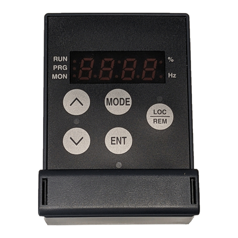
Toshiba TOSVERT VF Series User manual

E6581277⑥
TOSVERT VF series
Remote Keypad Instruction Manual
RKP002Z
.
Note
1. Read this manual carefully before using the product. After reading, the user should
keep this manual at hand to use it for maintenance and inspection in the future.
2. Please be informed that the contents of this document may be changed without notice.
*E6581277REV06*

E6581277
1
Safety precautions
On the inverter and in its instruction manual, important information is contained for preventing
injuries to users, damages to assets, and for proper use of the device.
Read the instruction manual attached to the inverter along with this instruction manual to completely
understand the safety precautions, the symbols and indications shown below. Please adhere to the
contents of these manuals at all times.
E
xplanation of markings
Marking
Meaning of marking
WARNING
Indicates that errors in operation will lead to death or serious injury.
CAUTION
Indicates that errors in operation will lead to injury
*1
to people.
NOTICE
Indicates that errors in operation will cause damage to physical property
*2.
*1 Such things as injury, burns or electric shock that will not require hospitalization or long periods of outpatient treatment.
*2 Physical property damage refers to wide-ranging damage to assets and materials.
Meanings of symbols
Marking Meaning of marking
Indicates a prohibition (Don't do it).
Detailed information on the prohibition is described in illustration and text in or near the symbol.
Indicates a mandatory action that must be followed.
Detailed information on the mandatory action is described in illustration and text in or near the
symbol.
Indicates a warning or caution.
Detailed information on the warning or caution is described in illustration and text in or near the
symbol.
Limitation of use
Safety precaution
Never use this unit with any device other than TOSVERT series inverters. Doing so will cause an accident.
Handling
WARNING
Prohibition
Never disassemble, modify or repair.
This can result in electric shock, fire and other injuries. Please call your Toshiba distributor for
repairs.
Do not place or insert any kind of object (electrical wire cuttings, rods, wires etc.) inside the
inverter.
This will cause a short circuit and result in electric shock or fire.
Do not allow water or any other fluids to come in contact with the option.
This will cause a short circuit and result in electric shock or fire.
Mandatory
action
Turn off input power before wiring. Check to make sure that the charge lamp (on the inverter
unit) is no longer lit.
Performing wiring without carrying out these steps can lead to electric shock.
Immediately turn the power off if the option begins to emit smoke, an unusual odor, or
unusual sounds.
Continuous use of the option in such a state will cause fire. If the option is left to be turned on
in that state, it can cause fire. Please call your Toshiba distributor for repairs.
Transportation and installation
WARNING
Prohibition
Do not install and operate the option if it is damaged or any of its components are missing.
This will result in electric shock or fire. Please call your Toshiba distributor for repairs.
Do not place any inflammable object near the option.
If flame is emitted due to failure in the option, it will lead to fire.

E6581277
2
WARNING
Mandatory
action
Electrical construction work must be done by a qualified expert.
Erroneous connection of power supply by someone who does not have that expert knowledge
will result in fire or electric shock.
An emergency stop device must be installed that is configured in accordance with the system
specifications.
If such an emergency stop device that can activate a mechanical brake by shutting off the
power supply is not installed, operation cannot be stopped immediately by the option alone,
thus resulting in an accident or injury.
Install an emergency stop device and an interlock that are configured in accordance with the
system specifications.
If the inverter cannot be stopped immediately via communication or the remote panel, it will
result in injury and accidents.
CAUTION
Prohibition
Do not install the option in any place subject to large vibrations.
The unit will fall due to the vibration, resulting in injury.
NOT
ICE
Prohibition
Do not connect a LAN cable or telephone modular cable to Remote Keypad.
Doing so will cause a failure or accident.
Mandatory
action
Transport or install under the environmental conditions prescribed in the instruction manual.
Transporting or installing under any other conditions will result in failure.
All options to be used must be those specified by Toshiba. (Refer to page 4.)
The use of options other than those specified by Toshiba will result in an accident.
Operations
WARNING
Prohibition
Do not touch terminals when the inverter's power is on even if the motor is stopped.
Touching the terminals while voltage is applied will result in electric shock.
CAUTION
Mandatory
action
▼ Set up “Communication error trip time (f803, f804, see the inverter instruction manual
for details)” to stop the inverter when Remote Keypad is deactivated by an unusual event
such as tripping, an operating error, power outage, failure, etc.
Deactivated Remote Keypad will cause an accident, if the “Communication error trip time” is
not properly set up.
NOTICE
Prohibition
Do not apply a dropping shock or other physical shocks.
Otherwise, damage or malfunction will result.
Do not pull the transmission cable and connection connector.
This can result in damage or malfunction.
Mandatory
action
Make sure to set the parameters correctly.
If you set the parameters incorrectly, it can damage the option or cause an accident by
unexpected action of the option. When you write the parameters in the option via a parameter
writer or operation panel, please transmit correct data

E6581277
3
Disposal
CAUTION
Mandatory
action
If you dispose of the option, have it done by a specialist in industry waste disposal*
1
.
If you dispose of the option by yourself, this can result in explosion of capacitor or production
of noxious gases, resulting in injury.
*1 Persons who specialize in the processing of waste and known as “industrial waste product collectors and
transporters” or “industrial waste disposal persons”. Please observe any applicable law, regulation, rule or
ordinance for industrial waste disposal.
Notes on operation
Notes
Avoid installing in a place where ambient temperature or/and humidity change sharply.
Keep the transmission cable separate from the power cable of the inverter to prevent the inverter from
malfunctioning due to electromagnetic noise.
It is recommended to install the unit on the panel board of a cabinet if it is used as a remote operation
panel. Improperly installed units
may
result in damage and malfunction.
The integrity of data storage is guaranteed for up to 10 years.
The operating life of EEPROM (data storage device) is 10000 operations.
Do not execute more than 10000 writing operations.
Do not turn off power or remove the connection cable between the inverter and Remote Keypad while a
copying operation is in progress. If the inverter power is turned off or the connection cable is removed
while parameters are being copied, data cannot be written correctly.
Do not copy data from Remote Keypad to inverter while the inverter is running. Some of the parameters
cannot be written when the inverter is in operation.
When a copying operation is executed between two inverters with different capacities, some of the
parameters that vary with the capacity of the inverters will also be copied. Therefore, when copying the
parameters between inverters with different capacities or voltage class, the type information parameters
of the inverter should always be initialized. See the inverter instruction manual on how to initialize their
parameters.

E6581277
4
Introduction
Thank you for purchasing Remote Keypad (RKP002Z ) for TOSVERT series inverters. Using this
product, panel operation, display and adjustment of the inverter can be remotely controlled from up to
5 meters away. You can copy data from one place to another and then execute data comparison
between the inverter and the memory of Remote Keypad or between the memories of Remote
Keypad itself.
Before using Remote Keypad, carefully read this instruction manual in order to completely and
correctly utilize Remote Keypad’s excellent performance.
After reading this instruction manual, please keep it handy for future reference.
- Part numbering
RKP
002
Z
–
1
Revision number
Cable length ( “Z” means “without cable” )
Model number of Remote Keypad
002: standard
Symbol of Remote Keypad
- Accessory check list
Remote Keypad is shipped together with the following accessories.
On opening the packing case, check to see if the following accessories are contained or not.
(1) Instruction manual .......................................... 1 copy
(English: E6581277)
(2) Mounting screws (M3 x 12mm) ...................... 4pcs.
(M3 screw tightening torque: 0.6 Nּm)
N.B.: Remote Keypad (Part number: RKP002Z) is not provided with connection cable between
an inverter and Remote Keypad. This should be purchased separately.
Part number of connection cable
between an inverter and an option unit
Cable length
CAB0011 1.3m, 4ft
CAB0013 3.7m, 12ft
CAB0015 5.0m, 16ft
Instruction
Manual

E6581277
5
Table of contents
Safety precautions····················································································································1
Introduction ·····························································································································4
Table of contents······················································································································5
1.
Overview ····························································································································6
2.
Names and functions of main parts··························································································7
3.
Connection and start-up ········································································································8
4.
Functions in detail ················································································································9
4.1.
Procedure to switch the operation mode·····································································9
4.2.
“REMOTE KEYPAD MODE”····················································································9
4.3.
“COPY MODE”·····································································································9
4.3.1.
Copying function “copy” ············································································· 10
4.3.2.
Simple copying function ················································································· 11
4.3.3.
Comparing function “comp” ········································································· 12
4.3.4.
Memory protection function “prot” ······························································· 13
4.3.5.
Memory initializing function “clr” ·································································· 14
4.3.6.
Remote Keypad parameter editing function ························································ 14
5.
Specifications···················································································································· 15
6.
Outline drawing·················································································································· 16
7.
Before contacting your Toshiba distributor ·············································································· 18
7.1.
Error message···································································································· 18
7.2.
Procedure to reset Remote Keypad········································································· 18
7.3.
Warning indications ····························································································· 19
7.4.
Other problems··································································································· 19
8.
Warranty ·························································································································· 20

E6581277
6
1. Overview
The following seven functions are available with Remote Keypad.
1. Function to serve as remote operation panel.
Remote Keypad can be used as a remote operation panel for the inverter.
2. Copying function
Data can be copied from one memory to another memory among the four memories, three
(memories A, B, C) on Remote Keypad and one on the inverter.
(i) Data copy from Remote Keypad to inverter
(ii) Data copy from inverter to Remote Keypad
(iii) Data copy from one memory to another memory on Remote Keypad
3. Simple copying function
Data stored in one of Remote Keypad’s memory may be transferred to the inverter’s memory by
simple operation of two keys.
4. Comparing function
Data stored in one of Remote Keypad’s memory can be compared with the data of inverter’s
memory. In addition, data stored within any of the 3 Remote keypad memories (A, B, or C) can be
compared with each other.
5. Memory protecting function
Data written on the inverter's memory and the memories of Remote Keypad are protected by this
function to protect against data damage.
6. Memory initializing function
One of the memories (A, B, or C) on Remote Keypad can be initialized by this function.
In addition, Remote keypad can be reprogrammed to default setting.
7. Remote Keypad parameter editing function
Remote Keypad parameters are programmable.
Memory configuration
Remote Keypad has three memories (A, B, and C) to retain three kinds of parameter for the inverter.
Memory A
Memory C
Memory B
To inverter
Communication cable between Remote Keypad
and the inverter (To be purchased separately)
Remote Keypad
To inverter

E6581277
7
2. Names and functions of main parts
The drawings below show names and functions of main parts.
Front view
8((8
COPY
MODE
RUN
PRG
MON
EASY
Hz
%
RUN
A
STOP
B
MODE
ESC
ENT
EASY
Hz lamp
*1
Lights when displayed
values are Hz.
% lamp
*1
Lights when displayed
values are %.
Operation keys
In “REMOTE KEYPAD MODE”, the key functions are the same as that of
the inverter. See the inverter instruction manual.
In “COPY MODE”, refer to the next page about the key functions.
MON lamp
Lights when the inverter
is in monitor mode.
PRG lamp
Lights when the inverter is
in parameter
setting mode.
RUN lamp
Lights when an ON
command is issued but no
frequency signal is sent
out. It blinks when
operation is started.
“COPY MODE” lamp
Lights when the Remote
Keypad is in “COPY MODE”
RUN key lamp
Lights when RUN key
is enabled.
Up/Down key lamp
Frequency setting by
up/down keys are
enabled while this lamp is
lit.
EASY lamp
*2
Lights when the inverter
is in EASY mode.
Potentiometer lamp
*3
Lights when the
potentiometer is enabled.
Potentiometer
*3
Operation frequency can
be changed when the
built-in potentiometer
lamp is lit
SFT
C
Display
Displays setting,
device status, trip
information, etc.
Reverse view
Communication
connector
Connect
communication
cable
Seal material
Seal material for
installation.
Communication
Mode Switch
Select communication
mode
RS485:
VF-AS1, etc.
LOGIC:
VF-S11,VF-nC1,
VF
-
A7, etc.
Screw hole
For mounting
screws
RS485
LOGIC
Screw hole
For mounting
screws
*1: These lamps are not lit when Remote Keypad is connected to VF-S11, VF-nC1, VF-S9, VF-A7, VF-P7 etc.
*2: The lamp is not lit when Remote Keypad is connected to an inverter without [EASY] key.

E6581277
8
Operation keys and their functions in “COPY MODE”
The operation key’s functions in “COPY MODE” are explained in the following table.
Operation
key
Function
Operation
key
Function
A
RUN
Memory A key
(Exclusive key for simple copying)
In the simple copying function, this key
is used to specify memory A of Remote
Keypad as the origin of transmission
data.
(In “REMOTE KEYPAD MODE”: RUN
key)
B
STOP
Memory B key
(Exclusive key for simple copying)
In the simple copying function, this key is
used
to specify memory B of Remote Keypad
as the
origin of transmission data.
(In “REMOTE KEYPAD MODE”: STOP key)
C
Memory C key
(Exclusive key for simple copying)
In the simple copying function, this key
is used to specify memory C of Remote
Keypad as the origin to transmission
data.
(In “REMOTE KEYPAD MODE”: DOWN
key)
SFT
SFT key
is used for selecting a function (copying,
comparing, protecting data) or for selecting a
memory from among inverter's memory and
memories (A, B, and C) of Remote Keypad.
(In “REMOTE KEYPAD MODE”: UP key)
MODE
ESC
ESC key
is used to return to previous setting
(In “REMOTE KEYPAD MODE”: MODE
key)
ENT
ENT key
is used to chose a function or memory or to
execute the chosen function.
(In “REMOTE KEYPAD MODE”: ENT key)
EASY
Invalid in “COPY MODE”
(In “REMOTE KEYPAD MODE”: EASY
key)
3. Connection and start-up
Connect Remote Keypad with the inverter according to the procedure stated below.
(1) Set Communication Mode Switch (refer to page.7) on the reverse side of Remote Keypad. The
position varies for the inverter series.
RS485: The inverter with RS485 (2-wire type) port (ex: VF-AS1, VF-nC3, VF-S15 etc.)
LOGIC: The inverter with Common Serial Port (ex: VF-S11, VF-nC1, VF-S9, VF-A7, VF-P7).
(2) Set communication baud rate (the inverter parameter “f800”) to 9600, 19200 or 38400bps
(programmed by default setting at the factory).
(3) Turn off the input power to the inverter, wait at least 15 minutes, and insure that the charge lamp
on the inverter is no longer lit.
(4) Connect an inverter-unit connection cable (optional) between the communication connector of
Remote Keypad and that of the inverter. At this time, be careful not to apply excessive force to the
connectors.
(See the instruction manual of the inverter for connection to the communication port of the inverter.)
(5) After wiring, fix the wires on the surface of the wall in the panel board and so on.
(6) Turn on the inverter, and Remote Keypad starts-up automatically showing a lit panel in the display
window.
(7) Using in “COPY MODE”, check that the “COPY MODE” lamp is lit.
(8) In order to change from “REMOTE KEYPAD MODE” to the “COPY MODE”, turn off the power of
inverter and insure that the Remote Keypad is also turned off. Then, turn on the power of the
inverter (Remote Keypad) while holding down the [ENT] key of Remote Keypad.
N.B.: When disconnecting Remote Keypad from the inverter, follow step (3) of the above procedure.
E6581277
9
4. Functions in detail
Remote Keypad can be used as remote operation panel (“REMOTE KEYPAD MODE”) or parameter
back-up device (“COPY MODE”). When the “COPY MODE” lamp is lit when turning power on, Remote
Keypad operates in “COPY MODE”, otherwise in “REMOTE KEYPAD MODE”.
4.1. Procedure to switch the operation mode
According to the procedure described in “3. Connection and start-up”, turn on the power of Remote
Keypad while holding down the [ENT] key of Remote Keypad. Operation mode changes.
4.2. “REMOTE KEYPAD MODE”
In “REMOTE KEYPAD MODE”, operation is the same as operation on the panel of the inverter. For
details, see instruction manual of the inverter. Data entered through Remote Keypad takes priority
over data entered through the inverter’s control panel. However, if Remote Keypad is deactivated by
an unexpected event such as an abnormality, the inverter’s input keys remain functional.
4.3. “COPY MODE”
In “COPY MODE”, storing and loading the parameters are permitted. Editing the parameters is not
permitted.
Key LED indication Key operation and description
“chc ”
→
“init”
→
”c0py”
When “COPY MODE” is initiated, “
chc
” is shown in the display window. This is
followed by “
init
” to indicate that the power supply is being initialized. Finally,
when ready to use the display shows “
”.
SFT
“c0py”
→
“c0mp”
→
”pr0t”
→
”clr”
→
”f- “
→
”c0py”
< Selecting a desired function >
Select the function with the [SFT] key. Each time the [SFT] key is pressed,
indication on the display changes from “
copy
” (copying function) to “
comp
”
(comparing function), to “
prot
” (memory protecting function), to “
clr
”
(memory initializing function), to “
f-
” (Remote Keypad parameter editing
function), and finally back to “
copy
” again in this order.

E6581277
10
4.3.1. Copying function “copy”
The data stored in a memory can be copied to another memory selected from among four
memories (the inverter's memory and Remote Keypad memories A, B, and C). Remote Keypad can
not be used to copy parameters from one inverter to another inverter of a different series.
N.B.: To copy the data to the inverter’s memory, do it when the inverter has stopped. If you copy
the data to the inverter while the inverter is running, some of the parameters fail to be copied.
Operating procedure
Key LED indication Key operation and description
“copy”
< Selecting a desired function >
Select “
c0py
” (copying function) with the [SFT] key.
(“
c0py
” automatically appears just after starting up.)
ENT
“copy”
→
“in”
< Entering the selected function >
After selecting “
c0py
” with the [SFT] key, press the [ENT] key. “
in
”
(selecting
inverter memory) appears in the display window.
SFT
“in”
→
“a”
→
“b”
→
“c”
→
“in”
< Selecting a memory to copy its data >
Select a memory to copy its data with the [SFT] key.
Each time the [SFT] key is pressed, the display changes as follow:
“
in
” (selecting inverter memory)
“
a
" (selecting memory A)
“
b
” (Selecting memory B)
“
c
” (selecting memory C)
and to “
in
” again in this order.
ENT
“in”
→
“in-a”
< Entering the memory to copy its data >
After selecting the memory to copy from, press the [ENT] key. Example: select
“
in
”, press [ENT] key, and “
in-a
” appears in the display window.
SFT
“in-a”
→
“in-b”
→
“in-c”
→
“in-a”
“a-in”
→
“a-b”
→
“a-c”
→
“a-in”
< Selecting a memory to transcribe copied data >
Select a memory to transcribe copied data with the [SFT] key.
Each time the [SFT] key is pressed, the display changes as follow
“
in-a
” (copying data from inverter memory to memory A)
“
in-b
” (copying data from inverter memory to memory B)
“
in-c
” (copying data from inverter memory to memory C)
and to “
in-a
” again in this order.
If the memory A, B, or C is selected as to copy data from, the display changes
accordingly (example shown in parentheses for memory A).
ENT
“in-a”
→
“f_ _ _”
< Executing copy function >
After selecting the memory to copy to (Example: “
in-a
”
select memory A as to
copy to), press the [ENT] key, and start copying. Then the display shows “
f
_ _
_”. This is the parameter title of the parameter being copied now. If Remote
Keypad is unable to copy the selected parameter, the display shows the parameter
title flashing in the display window. To continue copying, press [ENT] key.
“c0mp”
→
“end”
→
“_ _ _ _”
(4 digits)
< Completion of copying function >
After completing the copy operation, “
c0mp
” begins to flash to indicate that
Remote Keypad is comparing two sets of parameters. (Refer to “comparing
function” in section 4.3.3). When the comparison is end, it displays CRC code “_
_ _ _” (4 digits in hexadecimal number) of memory data for error detection after
displaying “
end
”. If the parameters are different, the comparison interrupts and
the parameter title number flashes on display. To continue comparison for next
parameter, press [ENT] key. When the comparison is end, the CRC codes of
original and copied memory data for error detection flash alternately after
displaying “
end
”.
The CRC code “_ _ _ _” (4 digits in hexadecimal number) changes depending on
the data condition.
ENT
“_ _ _ _”
→
”copy”
< Ending copying >
Press the [ENT] key and the indication in the display window returns to
“
copy
”.
- If the [ESC] key is pressed, Remote Keypad returns to previous status (except when executing).
- When the memory protection function is actuated, Remote Keypad inhibits copying data with “
prot
” appearing in
the display window.
- If there is no data in memory A of Remote Keypad upon selection as data to copy from, the display shows “
err.a
”
which means copying data is impossible. (When the memory B or C is selected in the same condition, “
err.b
” or
“
err.c
” appears in the display window
- In “
a-in”
,”
b-in”
and “
c-in”
, when the data of the inverter increases by the upgrade, the data not included
in memory A, B, and C is not changed.

E6581277
11
4.3.2. Simple copying function
The data stored in the memory A, B or C of Remote Keypad can be copied to the inverter's memory
with simple operation of two keys to select one of the memories A, B and C. Use this function to set
the same parameters to more than two inverters. Remote Keypad can not copy parameters to from
one inverter to another inverter of a different series. What differs from the “Copying function” in
Section 0 is the key operation and the contents of parameters to be copied are the same for both
functions. It is impossible to copy data from the inverter's memory to a memory of Remote Keypad
in this function.
N.B.: To copy data to the inverter’s memory, do it when the inverter has stopped. If you copy data
to the inverter while the inverter is running, some of the parameters may fail to be copied.
Operating procedure
Key LED indication
Key operation and description
A
RUN
“copy”
→
“a-in”
< Selecting and entering a memory to copy its data >
Press the key corresponding to the memory selected to copy data from, while
“copy” is being displayed.
[A] key: To copy data from memory A to the inverter's memory.
[B] key: To copy data from memory B to the inverter's memory.
[C] key: To copy data from memory C to the inverter's memory.
When memory A is selected to copy its data to the inverter's memory for example,
the display changes from “copy” to “a-in” (copying data from memory A to
inverter's memory).
ENT
“a-in”
→
“f_ _ _”
< Executing copy function >
After selecting the memory to copy from (to inverter, Example: select “a-in”),
press the [ENT] key, and start copying. Then the display shows “f_ _ _”. This is
the parameter title of the parameter being copied now. If Remote Keypad is unable
to copy the selected parameter, the display shows the parameter title flashing in the
display window. To continue copying, press [ENT] key.
“c0mp”
→
“end”
→
“_ _ _ _”
(4 digits)
< Completion of copying function >
After completing the copy operation, “c0mp” begins to flash to indicate that
Remote Keypad is comparing two sets of parameters. (Refer to “comparing
function” in section 4.3.3). When the comparison is end, it displays CRC code “_ _
_ _” (4 digits in hexadecimal number) of memory data for error detection after
displaying “end”. If the parameters are different, the comparison interrupts and
the parameter title number flashes on display. To continue comparison for next
parameter, press [ENT] key. When the comparison is end, the CRC codes of
original and copied memory data for error detection flash alternately after
displaying “end”.
The CRC code “_ _ _ _” (4 digits in hexadecimal number) changes depending on
the data condition.
ENT
“_ _ _ _”
→
“copy”
< Ending copying >
Press the [ENT] key and the indication in the display window returns to “copy”.
- If the [ESC] key is pressed, Remote Keypad returns to previous status (except when executing).
- When the memory protection function is actuated, Remote Keypad inhibits copying data with “
prot
” appearing in
the display window.
- If there is no data in memory A of Remote Keypad upon selection as data to copy from, the display shows “
err.a
”
which means copying data is impossible. (When the memory B or C is selected in the same condition, “
err.b
” or
“
err.c
” appears in the display window.)
- In “
a-in”
,”
b-in”
and “
c-in”
, when the data of the inverter increases by the upgrade, the data not included
in memory A, B, and C is not changed.
The same operation as above can also be used to copy data from memory B or memory C of Remote
Keypad to the inverter.
B
STOP
→
ENT
C
→
ENT
Since the [ A ], [ B ], and [ C ] keys are provided to be used
exclusively for the simple copying function, those keys cannot
be used for other functions.

E6581277
12
4.3.3. Comparing function “comp”
This function enables the operator to compare data stored in two memories selected from among
four memories (the inverter’s memory and Remote Keypad memories A, B, and C) as well as to
search for parameters that differ from each other.
The comparing function cannot be used for editing parameters because it is provided only for
searching parameters that differ from each other. Use the “REMOTE KEYPAD MODE” function
described in section 4.2 to edit parameters.
Operating procedure
Key LED indication Key operation and description
SFT
“c0py”
→
”c0mp” < Selecting a desired function >
Select “comp” (comparing function) with the [SFT] key.
ENT
”comp”
→
“in”
< Entering the selected function >
After selecting “comp” with the [SFT] key, press the [ENT] key and
“in” (selecting inverter memory) appears in the display window.
SFT
“in”
→
“a”
→
“b”
→
“c”
→
“in”
< Selecting a memory >
Each time the [SFT] key is pressed, the display changes as follow
“in” (selecting inverter memory)
“ a” (selecting memory A)
“ b” (selecting memory B)
“ c” (selecting memory C)
and to “in” again in this order.
ENT
“in”
→
“in a”
< Entering the memory >
After selecting the memory, press the [ENT] key. For example, select
“in”, press [ENT] key, and “in a” appears in the display window.
SFT
“in a”
→
“in b”
→
“in c”
→
“in a”
“a in”
→
“a b”
→
“a c”
→
“a in”
< Selecting a memory to compare its data with that of the previously
selected memory >
Each time the [SFT] key is pressed, the display changes as follow
“in a”: comparing data between inverter memory and memory A
“in b”: comparing data between inverter memory and memory B
“in c”: comparing data between inverter memory and memory C
and to “in a” again in this order.
If for example memory A is selected instead of “in” different
indication appears as shown in parentheses.
ENT
“in<a”
→
(flashing)
< Entering the selected memory to compare its data with the original >
After selecting “in a” (selecting memory A to compare its data with
that of the inverter's memory for example), press the [ENT] key, and
Remote Keypad starts comparing the data of the two memories with
each other.
ENT
“f000”
→
“f999”
< Executing data comparison (searching different parameters) >
Remote Keypad compares parameters consecutively while displaying
the parameter title. When Remote Keypad finds two parameters that
differ from each other, it discontinues comparing operation and shows
the parameter title flashing in the display window.
Press the [ENT] again to continue the comparing operation.
“c0mp”
→
“end”
→
“_ _ _ _” (4 digits)
< Comparing is complete >
After displaying “end”, the CRC code “_ _ _ _” (4 digits in
hexadecimal number) of memory data for error detection is displayed. If
the parameters are different, the CRC codes of original and compared
memory data for error detection flash alternately after displaying
“end”.
The CRC code “_ _ _ _” (4 digits in hexadecimal number) changes
depending on the data condition.
ENT
“_ _ _ _”
→
“comp”
< Ending comparing >
Press the [ENT] key and the indication in the display window returns to
“comp”.
- If the [ESC] key is pressed, Remote Keypad returns to previous status (except when executing).
w
<
w
<
w
<
w
<
w
<
w
<
w
<
w
<
w
<
w
<
w
<
w
<
w
<
w
<
w
<
w
<

E6581277
13
4.3.4. Memory protection function “prot”
The memory protection function protects the selected memory from being overwritten.
When this function is initiated copying data to the memory is prohibited. Reading the memory data is
permitted.
When all the memories are initialized by memory initialization function (clr), the LED indications
are as follows:
“in”, “a”, “b”, “c” = “off”, “sup” = “on”
This is also the default setting at the time of shipment.
Operating procedure
Key
LED indication Key operation and description
SFT
“copy”
→
“com
p”
→
“prot”
< Selecting a desired function >
Select “prot” (memory protection function) with the [SFT] key.
ENT
“prot”
→
“in”
< Entering the selected function >
After selecting “prot” with the [SFT] key, press the [ENT] key and “in”
(selecting inverter memory) appears in the display window.
SFT
“in”
→
“a”
→
“b”
→
“c”
→
“sup”
→
“in”
< Selecting a memory to protect its data >
Each time the [SFT] key is pressed, the display changes as follow
“ in” selecting inverter memory
“ a” selecting memory A
“ b” selecting memory B
“ c” selecting memory C
“sup” special parameter selection
(
*
1)
and to “in” again in this order.
ENT
“in”
→
“off”
“in”
→
“on”
< Entering the memory to protect its data >
After selecting “in” (selecting inverter memory, by way of example) with the
[SFT] key, press the [ENT] key and the display shows the present memory
protection status. (When “on” appears on the display, the selected memory
is protected. When “off” appears on the display, the selected memory is
not protected.)
SFT
“off”
→
“on”
→
“off”
< Protecting the selected memory >
Each time the [SFT] key is pressed, the indication in the display changes
“on” protecting the selected memory (write prohibited)
“off” canceling protection of the selected memory (write permitted)
alternately.
ENT
“on”
→
“prot”
< Executing protection of the selected memory >
After selecting “on
” (protecting the selected memory, by way of example) with
the [SFT]key, press the [ENT]key. Remote Keypad starts protecting the
selected memory (canceling the protection in case of “off”) and the
indication in the display window returns to “prot”.
-If the [ESC] key is pressed, Remote Keypad returns to previous status (except when executing).
(*1) The Protecting operation of “
sup
” is different from that provided for other memories and is shown below.
With the same inverter types With different inverter types
(capacity, voltage class) (capacity, voltage class)
sup
Standard parameters
Special parameters
sup
Standard parameters
Special parameters
on
–
on
–
off
off
(
*
2)
–
–
“
”: Protection disabled (write permitted), “–”: Write protected (write prohibited)
(*2) In this case, copying operation of parameters from one inverter to another inverter of a different capacity or a different voltage
class.

E6581277
14
4.3.5. Memory initializing function “clr”
A selected one of the memories either memory A, B, C of Remote Keypad is enable to be initialized
with this function. In addition, all memories including system memory of Remote Keypad is also
enable to be initialized.
Operating procedure
Key LED indication Key operation and description
SFT
“copy”
→
“comp”
→
“prot”
→
“clr”
< Selecting a desired function >
Select “clr” (memory initializing function) with the [SFT] key.
ENT
“clr”
→
“a”
< Entering the selected function >
After selecting “clr” with the [SFT] key, press the [ENT] key and “a”
(selecting memory A) appears in the display window.
SFT
“a”
→
“b”
→
“c
→
“sys”
→
“a”
< Selecting a memory to initialize >
Each time the [SFT] key is pressed, the display changes as follow
“ a” selecting memory A
“ b” selecting memory B
“ c” selecting memory C
“sys” selecting all memories (reprogram to default setting)
and to “a” again in this order.
ENT
“a”
→
“off”
< Entering the memory to initialize >
After selecting a memory for initialization (selecting memory A, by way of
example) with the [SFT] key, press the [ENT] key and “off” appears in the
display window.
SFT
“off”
→
“on”
→
“off”
< Initializing the selected memory >
Each time the [SFT] key is pressed, the display changes
“on”(to initialize selected memory)
“off” (not to initialize the selected memory).
alternately.
ENT
“on”
→
“init”
→
“clr”
< Executing initialization of the selected memory >
After selecting “on” with the [SFT] key, press the [ENT] key and Remote
Keypad starts initializing the selected memory with the indication “init”
appearing in the display window. When the initialization of the selected
memory is complete, the indication in the display window returns to “clr”.
- If the [ESC] key is pressed, Remote Keypad returns to previous status (except when executing).
- When the memory protection function is actuated, Remote Keypad prohibits the initialization of memory with
“
prot
” appearing in the display window.
4.3.6. Remote Keypad parameter editing function
This function allows the user to edit the parameters of Remote Keypad.
Remote Keypad parameter list
Title Function Description
f-01
Software version
displaying Display shows the software version of Remote Keypad.
f-02
Automatic comparing
function
Automatic comparing function can be turned on or off.
0
: Not executing comparison after copying
1
: Executing comparison after copying (default)
Warning
It is recommended to set the automatic comparing function “
f-02
” to “
1
” (default). When “
0
” is selected,
programming errors (caused by environmental circumstances, peripheral devices, etc.) will not be automatically
detected. This could result in an accident, if the inverter is operating with the wrong parameters.

E6581277
15
Operating procedure
Key LED indication
Key operation and description
SFT
“copy”
→
“comp”
→
“prot”
→
“clr”
→
“f- ”
< Selecting a desired function >
Select “
f-
” (Remote Keypad parameter editing function) with the [SFT] key.
ENT
“f- ”
→
“f-01”
< Entering the selected function >
After selecting “
f-
” with the [SFT] key, press the [ENT] key and “
f-01
”
appears in the display window.
SFT
“f-01”
→
“f-02”
< Selecting a parameter title to edit or display >
Each time the [SFT] key is pressed, the display changes
“
f-01
”
Software version displaying
“
f-02
”
Automatic comparing function
alternately.
ENT
“f-02”
→
“ 1”
( “f-01”
→
“ 100” )
< Entering a parameter title to edit or display >
If “
f-02
” is selected with the [SFT] key and the [ENT] key is pressed, the
current value (“
1
”: Executing comparison after copying by way of example)
appears in the display window. If “
f-01
” is selected as parameter to display,
the indication of Remote Keypad software version appears as shown in
parentheses.
SFT
“1”
→
“ 0”
→
...
< Changing a value of selected parameter >
Each time the [SFT] key is pressed, indication in the display window alternately
changes between “
1
” and “
0
”. However the software version does not
change.
ENT
“0“
→
“0“ (flashing)
→
“f-02“
< Executing edit parameter >
After selecting “
0
” (Not executing comparison after copying) with the [SFT]
key, press the [ENT] key and Remote Keypad starts writing the parameter
value to its memory, and flashes the value in the display window. When the
writing is complete, indication of the display returns to the parameter title
(“
f-02
”).
- If the [ESC] key is pressed, Remote Keypad returns to previous status (except when executing).
- The memory protection function (write protection) cannot protect Remote Keypad parameter.
- The memory initialization function initializes Remote Keypad parameter when “
sys
(selecting all memories)” is
selected.
5. Specifications
Item Specifications
Part number RKP002Z
Applicable model Model with either an RS485 (2-wire type) connector or a common serial connector
(optional) with a baud rate of 9600, 19200 or 38400bps.
Communication Automatic search:
Baud rate: 9600, 19200, 38400bps
Parity: even, odd, none
Communication method:
RS485 (2-wire type)
or Common Serial Communication, switched by Communication
Mode Switch
Service environment
Indoors, altitude 1000m or less, not exposed to direct sunlight, corrosive gas, explosive
gas, combustible gas, oil mist, dust, metal powder, etc.
Ambient temperature
-10 to +50°C
Storage temperature
-25 to +65°C
Relative humidity 20 to 93% (free from condensation and vapor)
Vibration 5.9m/s
2
(0.6G) or less (10 to 55Hz)
Cooling method self-cooling

E6581277
16
6. Outline drawing
Following is the outline drawing of Remote Keypad
(Unit: mm)
BOX color: JIS N1.5(Black)
Approx. mass: 0.11kg
98
4-M3 Screw
31
4.6
63
10.4
16.4

E6581277
17
Mounting
Mount Remote Keypad on the front of the panel board as illustrated below.
On the front of the panel board, cut the area shown below for mounting Remote Keypad. Then, fix Remote
Keypad on the panel board with the mounting screws (M3 x 12) supplied as accessories. (M3 screw
tightening torque: 0.6 N
ּ
m)
unit : mm
(The front view of the panel board)
4-φ4.0 hole
63±0.3
19
21
98±0.3

E6581277
18
7. Before contacting your Toshiba distributor
If a problem arises, please see the following trouble-shooting tables. If the problem can not be
solved, please contact a Toshiba distributor.
7.1. Error message
Malfunction indications: Indicated by flashing LED display
Error Code Problem and Solutions
LED display
raMe
RAME
RAM built in Remote Keypad is abnormal.
If the same indication appears after resetting Remote Keypad, it needs to be repaired.
roMe
R
OME
ROM built in Remote Keypad is abnormal.
If the same indication appears after resetting Remote Keypad, it needs to be repaired.
cpUe
CPUE
Micro controller unit of Remote Keypad is abnormal.
If the same indication appears after resetting Remote Keypad, it needs to be repaired.
btNe
BTNE
Is any key kept being pressed (for about 10 seconds)?
This indication will automatically cancel itself.
If the display shows the indication after turning off all keys, it needs to be repaired.
N.B.: In “REMOTE KEYPAD MODE” this is only alarm displaying. The operation keys are also
effective while the display is showing this alarm message.
eePe
EEPE
EEPROM built in Remote Keypad is abnormal.
If the same indication appears after writing data again, it needs to be repaired.
coMe
C
OME
Abnormal communication
Check the connection of the inverter’s serial communication cable, Communication Mode Switch
on the reverse of Remote Keypad, the baud rate (inverter’s parameter “
f800
”) and
transmission delay time (inverter’s parameter “
f805
” is recommended to be set to 0).
This indication will automatically cancel itself.
If abnormality is not found after checking and resetting Remote Keypad, it needs to be repaired.
7.2. Procedure to reset Remote Keypad
There are two methods to reset the micro controller unit inside Remote Keypad.
- Method 1:
Reset the power source of Remote Keypad.
- Method 2:
B
STOP
→
“clr”
→
B
STOP
If [STOP] key is pressed while an error message is displayed, “clr” flashes for one second. If
you press the [STOP] key again when “clr” flashes, Remote Keypad will be reset.

E6581277
19
7.3. Warning indications
Warning indications: Indicated by flashing LED display.
Warning Code
Problem and Solutions
LED
display
prot
PROT
The target memory to copy data or to initialize is write protected. Copying any data to
the memory or initializing the memory cannot be executed. Press the [ESC] key to
cancel.
deVe
DEVE
The type of device is different (different in series or voltage class or capacity of inverter).
Press the [ENT] key to copy between two inverters of different capacity or voltage class.
Press the [ESC] key to cancel copying. If “sup” (system area parameters) protection
has been disabled by setting “prot”(memory protection) to “off”, the copying
cannot be executed even if the [ENT] key is pressed. Copying to the inverter of a
different series is impossible.
After copying between two inverters with different capacities, the type information
parameters depending on the inverter capacity or voltage class should be initialized. See
the inverter instruction manual on how to initialize them.
erRa
erRb
erRc
ERRA
ERRB
ERRC
Indicated memory is not found or has been corrupted.
This indication appears when memory A, B, or C is selected to copy data from, to
compare data to, or to protect data, but no data can be found in the selected memory
(including the case when power was turned off during the previous copying operation),
or a CRC code error occurred in the selected memory. Press the [ESC] key to cancel.
In this case the data has to be rewritten.
f_ _ _
a_ _ _
c_ _ _
(title
number)
F_ _ _
A_ _ _
C_ _ _
Indicates the title number of the parameter that was found to be different while using
comparison function, or that cannot be written while using the copying function. Press
the [ENT] key to continue, the [ESC] key to cancel.
When Remote Keypad did not find any data in one memory, it flashes “%” in case the
data is missing in the memory that was selected first, or “Hz” if it is missing in the
memory that was selected second. This may happen parameter data may be missing
when the software versions of two inverters are different.
N.B.: Parameter titles are written to the inverter memory in consecutive order. When
Remote Keypad indicates missing or mismatched data by flashing a parameter title
number on the display, all prior paramete
r titles will have been written to the inverter
already.
Remote Keypad may stop at the following parameters during the parameter copying,
but
this is no problem because these parameters are not needed to copy into the inverter.
Please press the [ENT] key to continue the comparison.
In this case, CRC code will alternately flash when the comparison is completed.
This situation can be prevented by making the same condition (the state of
input or output
terminals, and communication options) of the inverter while copying to the inverter.
However, the unique parameters like IP address cannot be set to same value.
c130,c151,c152,c159,c202,c502,c503,c517~c522,c524,
c525~c536,c555,c556,c800
_ _ _ _
(4 digits
CRC
code)
_ _ _ _
When CRC code difference of parameters was found as a result of comparison, two
alternating CRC code indicates appear in the display window. In this case, there is a
different parameter. If the title of different parameter is not found, execute comparison
again after setting “sup” in memory protection function to “off”.
7.4. Other problems
Phenomenon Problem and Solutions
Display is
extinguished.
Check the connection of the serial communication cable.
Check the kind of the serial communication cable.
Check that the power of the inverter is turned on.
% lamp and Hz
lamp are not lit
When Remote Keypad is connected to the following inverters, % lamp and Hz lamp is
not lit. VF-S11, VF-nC1, VF-S9, VF-A7, VF-P7, etc.
Key is not
effective
It needs to be repaired.
[EASY] key is effective only for the inverter with [EASY] key.
Parameters
can’t be written
Some parameters can’t be written while the inverter is running. See the instruction
manual of the inverter.
Copying the parameters between inverters of different series is impossible.
Other manuals for TOSVERT VF Series
1
This manual suits for next models
1
Table of contents
Other Toshiba Keypad manuals

Toshiba
Toshiba RKP002Z User manual

Toshiba
Toshiba Compliant Manager BMS-CM1280TLE User manual

Toshiba
Toshiba RKP007Z User manual

Toshiba
Toshiba RKP007Z User manual

Toshiba
Toshiba RKP007Z User manual

Toshiba
Toshiba RKP004Z User manual

Toshiba
Toshiba RKP004Z-0 User manual

Toshiba
Toshiba RKP004Z User manual

Toshiba
Toshiba RKP007Z User manual