©Vantage, 7/19/2016 / IS-00705-C Vantage, Arteor Keypad (Engine) — MODEL: KSS14AR-.. & KSR14AR-.. page 1 of 2
2
2. Connect the 2 wire pigtail
to the station bus on the
back of the station.
Connect the 4-wire AUX.
connector if needed.
Screw the mounting plate
into the wall box.
1
Arteor Plate
Vantage
Keypad engine
1. Snap the Vantage keypad engine
into the mounting plate.
Arteor Faceplate
Cover
3
3. Snap the cover plate onto
the assembled station.
4
4. The finished station is ready when the
System is programmed.
INSTALLATION
VANTAGECONTROLS.COM VANTAGE INSTALL GUIDES
2168 West Grove Parkway, Suite 300, Pleasant Grove, UT 84062 USA
Telephone: 801 229-2800 ●Fax: 801 224-0355 Vantage, Arteor Keypad (Engine) — MODEL: KSS14AR-.. & KSR14AR-..
Overview
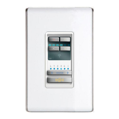
The Arteor™, European style keypad from Legrand®, enhances the range
of international design options available from Vantage™. Stations have
four buttons, and support the auxiliary connection port (new four wire
version). Each of the programmable buttons are evenly backlit with a
built in diffuser and three color*LEDs. The programmable backlight
color indicates the button status. Arteor stations connect to Vantage,
InFusion Systems via the InFusion controller’s station bus.
Faceplates and mounting brackets are sold separately from Legrand®
distributers around the world. See Legrand link later in this document
for more Adorne faceplate styles.
*Notes to Installer
Three-color LEDs:
Current technology does not allow LED suppliers to guarantee
color consistency. It is common to have a slight difference among
LEDs used to back light keypads. Because of this slight LED
manufacturer inconsistency, slight variations in color may be
present among keypads.
Specifications
Description Specification
Vantage, engine with buttons
dimensions - HWD
1.77” x 1.77” x 0.84”
45mm x 45mm x 21mm
Vantage, Arteor, button area
dimensions - HW
1.76” x 1.76”
44.7mm x 44.7mm
Arteor Faceplate dimensions
HWD (above sample, other
styles may be available)
3.64” x 3.64” x 0.39”
92.5mm x 92.5mm x 10mm
Arteor mounting plate
dimensions HW (above sample,
other styles may be available)
3.12” x 3.33” (tabs)
79mm x 85mm (tabs)
Faceplate finishes See link below*
Weight
(Vantage engin
&
buttons only) 0.8 oz. or 22.68g
Surge Suppression Yes
Maximum Gangs Please contact your local Vantage dealer
LED Button Status RGB – Set Custom Color
in Design Center
Button Touch Sound Yes
Button Configuration 4-buttons – 2x2
Button Colors Magnesium or White
Wiring Connections 2 Wire 600V pigtail (included)
4 wire aux. pigtail (order separate)
Power for Aux. External Devices
15 mA @ 12V DC
Station Bus Polarity Auto-Switching
Station Wiring configuration Daisy-chain/Star/Branch
Station Bus Specification
2C, 16AWG / 1.31mm2, twisted, non-
shielded, <30pF per foot. Separate a
minimum of 12" / 30.5cm from other parallel
communication and/or high voltage runs.
Power 24V/36V controllers via Station Bus
Station Bus Power Draw 36V &
24V Controller = 0.75Watts
Addressing self addressing through
configuration in software
Faceplate Finishes Faceplates and mounting plates hardware
available from Legrand.
Ambient Operating
Temperature 32-95°F -or- 0-35°C
Ambient Operating Humidity 5-95% non-condensing
UL, CUL, and CE Yes
Ordering Faceplates
*For additional faceplate information, click the link below:
LINK: ARTEOR-FINISHES
Please contact your local Vantage dealer for available faceplate finishes
and additional information in your country.
System Requirements
This station is compatible with InFusion Design Center 3.6 or higher. For
new projects it is recommended that firmware and software be kept to
the most current release.
Installation
Installation of Vantage products should be performed or supervised by
a Certified Vantage Installer. The Vantage Keypad Station installation is
very simple.
Faceplates and mounting brackets are sold separately from Legrand
distributers around the world. See Legrand link later in this document
for more Arteor faceplate styles.
square buttons - KSS14AR round buttons - KSR14AR
The two button styles from Vantage shown above.
Buttons are shown with two of the many Arteor faceplates.
Configuration
From Design Center:
Select the station and click the configure stations button
The button LEDs will blink rapidly
Press any button three times.
-or-
Type the serial number in the Design Center project file, using this
method the station will automatically be configured when the system
is programmed.
oNote, if the serial number contains an alpha character ignore
when typing in the serial number.
Diagnostic LED Information
In normal operation each button’s LED respond as programmed in
Design Center. Before configuring or if a problem exists, the station
LEDs, in unison, act as status LED indicators. the LEDs status response
is off-(meaning status off, or normal operation) or all LEDs flash in a 2,
3, 4 or 5 blink pattern indicating status information.

