E6581592②
1. Make sure that this instruction manual is delivered to the end user of Remote
Keypad.
2.
Read this manual before installing or operating the Remote Keypad. Keep it
in a safe place for reference.
3. All information contained in this manual is subject to change without notice.
Please confirm the latest information on our web site “www.inverter.co.jp”.
Safety Precautions
On the inverter and in its instruction manual, important information is contained for preventing
injuries to users, damages to assets, and for proper use of the device.
Read the instruction manual attached to the inverter to understand the safety
precautions, the symbols and indications completely.
Please adhere to the contents of these manuals at all times.
Please refer to the inverter’s instruction manual for detail functions and operation of this unit.
Limitation of use
Never use the Remote Keypad with any device other than TOSVERT series inverters.
Doing so may cause an accident.
Handling in general
Never
Never disassemble, modify or repair the Remote Keypad.
The disassembling may cause electric shocks, fire or injuries.
For repairs, call your sales/repair agency.
Prohibited
Do not put or insert foreign objects such as waste cable, bars or wires into the
Remote Keypad. It may lead to electric shocks or fire.
Do not splash water over the Remote Keypad.
It may lead to electric shocks or fire.
Do not apply a dropping shock or other physical shocks.
Otherwise, damage or malfunction will result.
Mandatory
Turn off the power immediately in case of any abnormalities such as smoke,
smell, blind display or abnormal noise.
Neglect of these conditions may lead to fire.
For repairs, call your sales/repair agency.
Operate under the environmental conditions prescribed in this instruction manual.
Operations under any other conditions may result in malfunction.
Disposal
Prohibited
If you dispose off the Remote Keypad, have it done by a specialist in industrial
waste disposal*.
Improper disposal may cause to produce noxious gases and result in accident.
(*) Persons who specialize in the processing of waste and known as “Industrial
Waste Product Collectors and Transporters” or “Industrial Waste Disposal
Persons.” If the collection, transport and disposal of industrial waste is
someone who is not licensed for that job, it is a
punishable violation of the law
(Laws in regard to cleaning and processing of waste materials).
Installation
Prohibited
Do not install or operate the Remote Keypad if it is damaged or any part of it is missing.
Operating the defective product may lead to electric shocks or fire.
For repairs, call your sales/repair agency.
Do not connect a LAN or telephone modular cable to the Remote Keypad.
Doing so may cause a malfunction or accident.
Do not pull on the cable and the connector.
It may cause damage or malfunction.
Mandatory
Use an emergency stop device and an additional safety device with your system
to prevent a serious accident due to the Remote Keypad malfunctions.
Usage without any emergency stop device and any additional safety device may
cause an accident or injury.
Use the Toshiba-specified cable for connecting the Remote Keypad.
The use of any other cable may cause a malfunction.
Do not install the Remote Keypad in any place subject to vibrations or it may fall.
This may lead to the product falling and causing injury.
Accessories
Remote Keypad is shipped together with the following accessories.
On opening the packing box, check to see if the following accessories are contained or not.
(1) User’s manual...................................................................1 copy
(E6581592)
(2) Key cover...........................................................................1 pcs.
(3) Mounting screws (M3 x 10mm)..........................................4 pcs.
(M3 screw tightening torque: 0.6 Nm)
Optional parts list
These are not provided with Remote Keypad. They should be purchased separately.
Interconnection cable (1m)
Interconnection cable (3m)
Interconnection cable (5m)
* Please connect the connector of the extended back of panel, between the
communication connector of the inverter by this cable.
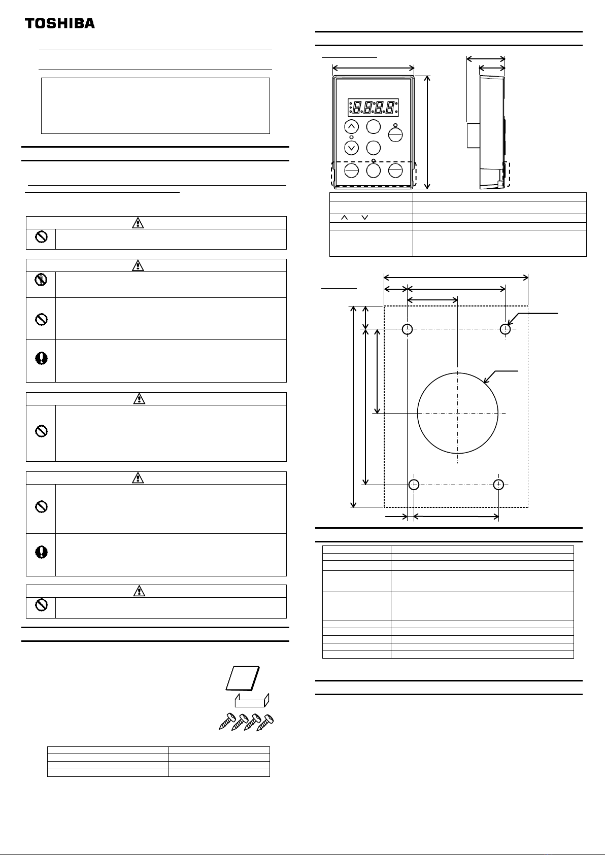
Outline drawing
Outline drawing
Mounting
Product Specification
Communication
configuration
Baud rate: 9600, 19200, 38400 bps (Automatic detection)
Parity: Even, Odd, None (Automatic detection)
Environment
Indoor operation at an altitude of 3,000m or less.
Free from direct sunlight, potentially corrosive or explosive gases,
steam, dust particles, dust/dirt, and machining fluids including
grinding liquid and coolant.
20 to 93% (free from condensation and vapor)
5.9m/s2 (0.6G) or less (10 to 55 Hz) (IEC60068-2-6)
IP54 (under the condition to be installed on flat panel) *3
*1: Please check the newest application model with the operation manual of each the inverter.
*2: When you apply to VF-FS1, please set up f829=1(Modbus RTU).
*3: You should confirm it on your final product, because it depends on the coarseness or the flatness of your panel.
Warranty
Any part of the Remote Keypad that is proved to be defective will be repaired free of charge
under the following conditions:
1. This product will be repaired free of charge, if problem/fault occurs under normal handling
within one year of delivery and is caused obviously by a design or manufacturing defect.
2. The warranty applies only to the delivered product.
3. For the following kinds of failure or damage, the repair cost shall be borne by the customer
even within the warranty period.
i) Failure or damage caused by improper or incorrect use or handling, or unauthorized
repair or modification of the Remote Keypad.
ii) Failure or damage caused by fallings or accidents during transportation after the
purchase.
iii) Failure or damage caused by fire, salty water or wind, corrosive gas, earthquake, storm
or flood, lightning, abnormal voltage supply, or other natural disasters.
iv) The damage due to the use of Remote Keypad for non-intended purposes.
4. If an additional warranty is provided then those conditions will also apply.
Operation key Function
[RUN], [STOP / RESET]
RUN: Operation(*1) STOP/RESET: Stop(*1)
Case of the trip, it is reset by STOP/RESET key pressed twice.
[ ], [ ]
Up or down for setting parameters.
Same as "MODE key" and "ENT key" of the inverter.
[FWD / REV],
[LOC / REM]
The function is based on inverter series. Refer to the operation manual
of the inverter for the contents and setup. FWD/REV is used forward
run/revers run selection etc., LOC/REM is used for local/remote change
etc..
*1: Parameter setup is required. It is effective when a panel (extended panel) is selected.
Applicable board thickness:
key cover location
REM
RESET


