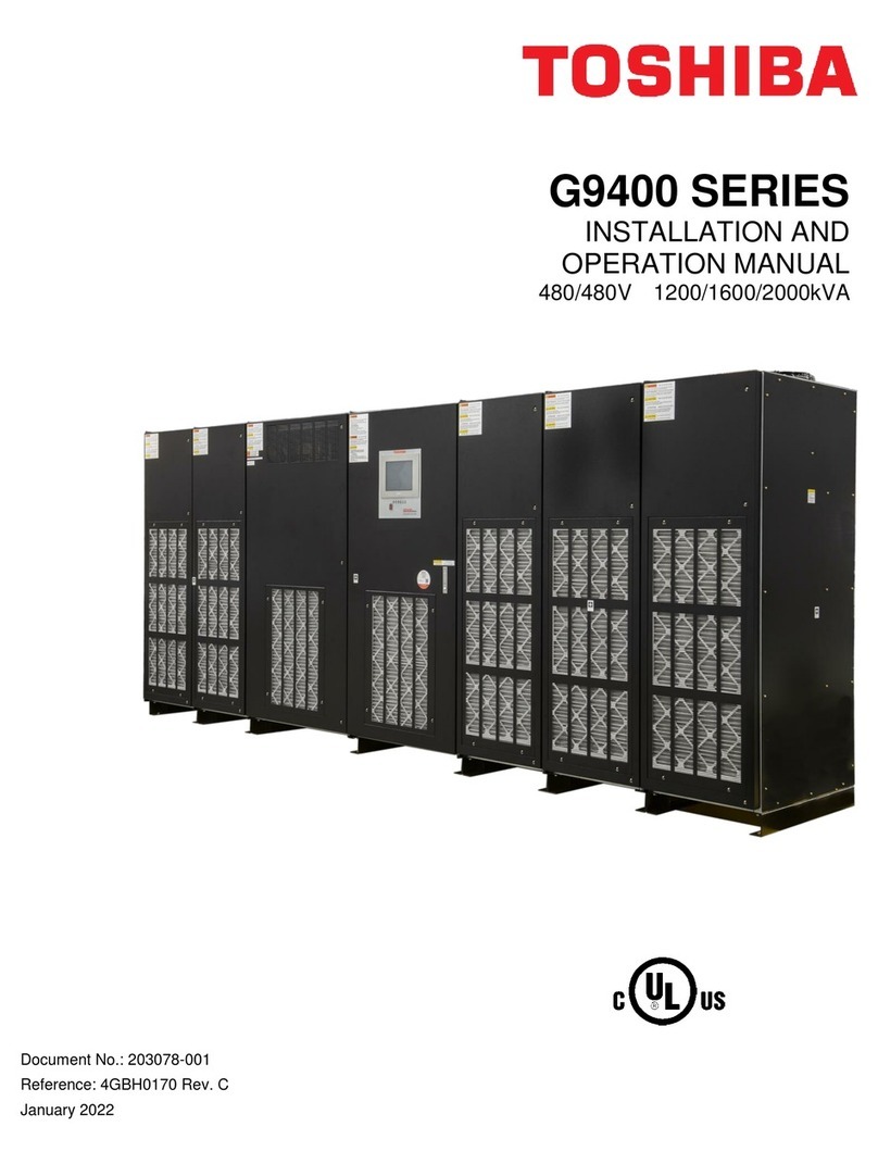
G9000 Series UPS Installation and Operation Manual –61480-017 i
Table of Contents
Table of Contents...................................................................................................................................................................i
List of Tables.........................................................................................................................................................................ii
List of Figures.......................................................................................................................................................................iii
1How to use this Manual............................................................................................................................................1
1.1 Notice Icons.................................................................................................................................................................1
1.2 Qualified Personnel.....................................................................................................................................................2
2INTRODUCTION.........................................................................................................................................................3
2.1 Safety Precautions......................................................................................................................................................4
3GENERAL...................................................................................................................................................................7
3.1 DEFINITIONS..............................................................................................................................................................8
3.2 OPERATION OVERVIEW...........................................................................................................................................9
3.2.1 Normal operation: Load power supplied by each system UPS inverter..................................................................9
3.2.2 Bypass Operation: Load Power supplied through UPS internal static bypass line...............................................10
3.2.3 Battery Operation: Load Power supplied by UPS battery.....................................................................................11
3.2.4 Battery Charging Operation ..................................................................................................................................12
3.2.5 UPS Parts Location...............................................................................................................................................13
3.2.6 PCB Layouts. ........................................................................................................................................................16
3.3 SPECIFICATIONS ....................................................................................................................................................20
4OPERATOR CONTROLS AND INDICATORS........................................................................................................25
4.1 LED DISPLAY...........................................................................................................................................................25
4.2 EPO BUTTON (Emergency Power Off button) (7)....................................................................................................26
4.3 LIQUID CRYSTAL DISPLAY (8)...............................................................................................................................26
4.3.1 Test Mode Options................................................................................................................................................26
4.3.2 Menu .....................................................................................................................................................................26
4.3.3 Input Power Failure...............................................................................................................................................30
4.3.4 Fault Indication......................................................................................................................................................31
4.4 EXTERNAL AUX CONTACT INPUT AND OUTPUT TERMINAL BLOCKS.............................................................31
4.4.1 Aux Contacts - Input..............................................................................................................................................31
4.4.2 Aux Contacts - Output...........................................................................................................................................34
4.5 RemotEye®INTRODUCTION...................................................................................................................................37
4.6 CONNECTOR DEFINITION......................................................................................................................................41
5INSTALLATION AND OPERATION.........................................................................................................................42
5.1 TRANSPORTATION AND INSTALLATION..............................................................................................................42
5.2 INSTALLATION PROCEDURE.................................................................................................................................42
5.3 PROCEDURE FOR CABLE CONNECTIONS..........................................................................................................43
5.4 OPERATING PROCEDURES...................................................................................................................................65
6RESPONSE TO UPS FAILURE...............................................................................................................................71
7PARTS REPLACEMENT..........................................................................................................................................72
8FAULT CODES.........................................................................................................................................................73
9DAILY INSPECTION ................................................................................................................................................78
APPENDIX A –Installation Planning Guides (IPG) & Outline Drawings .......................................................................79
APPENDIX B –Index...........................................................................................................................................................89
