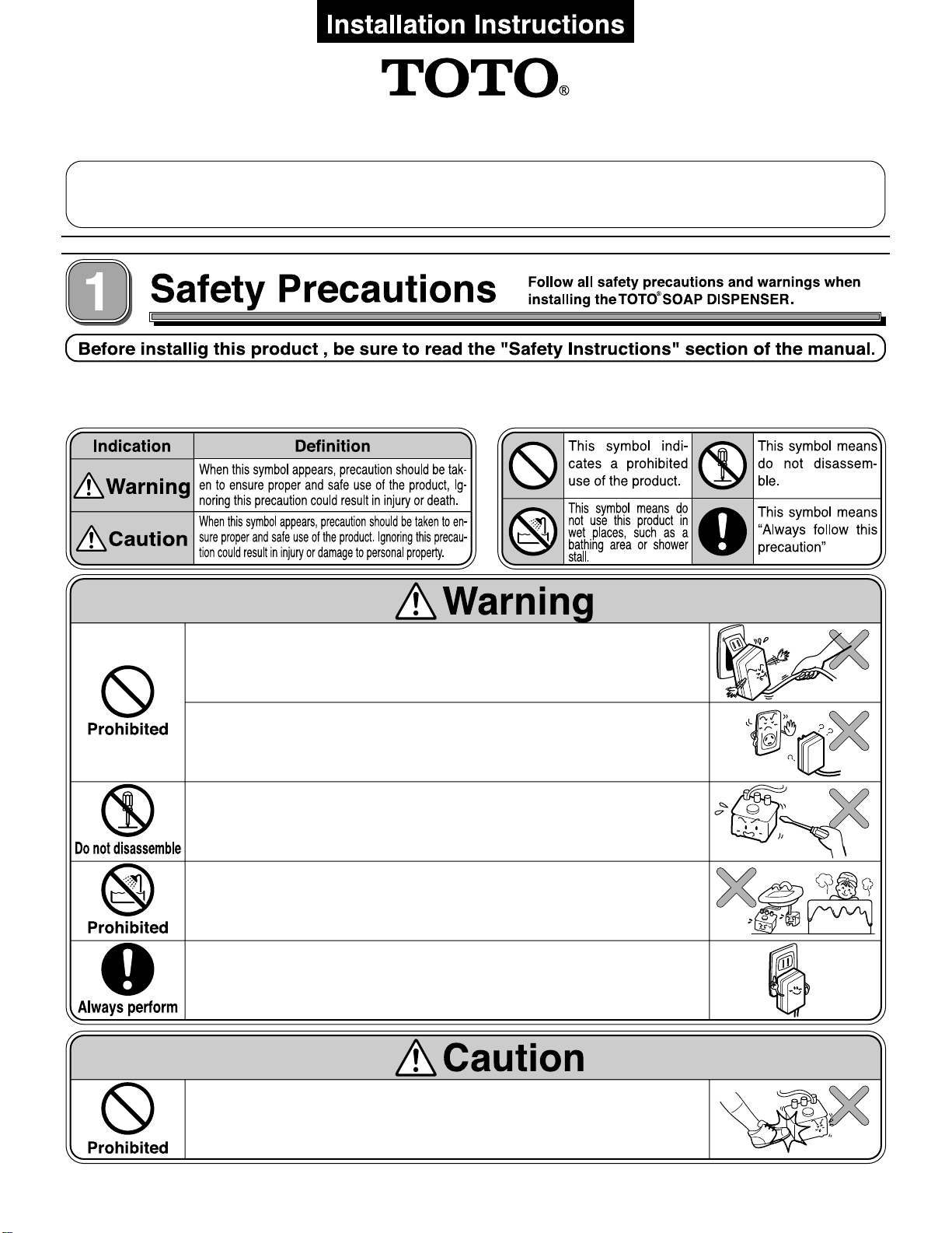
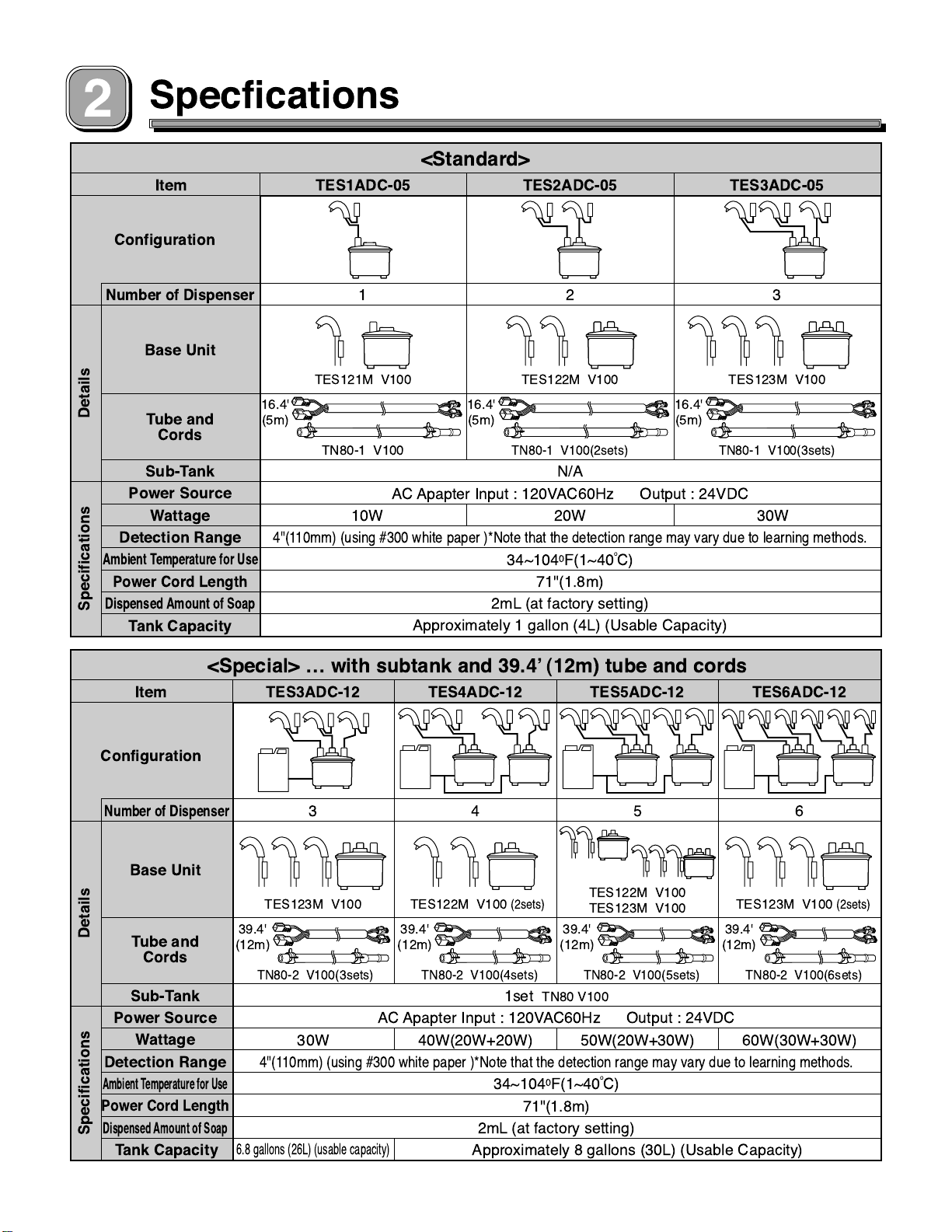
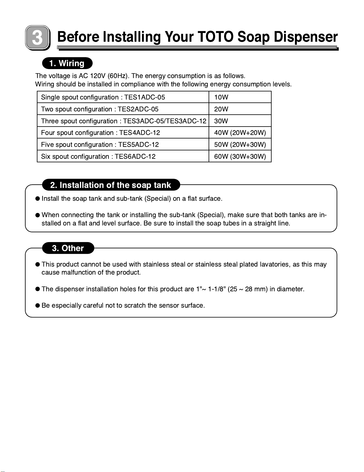
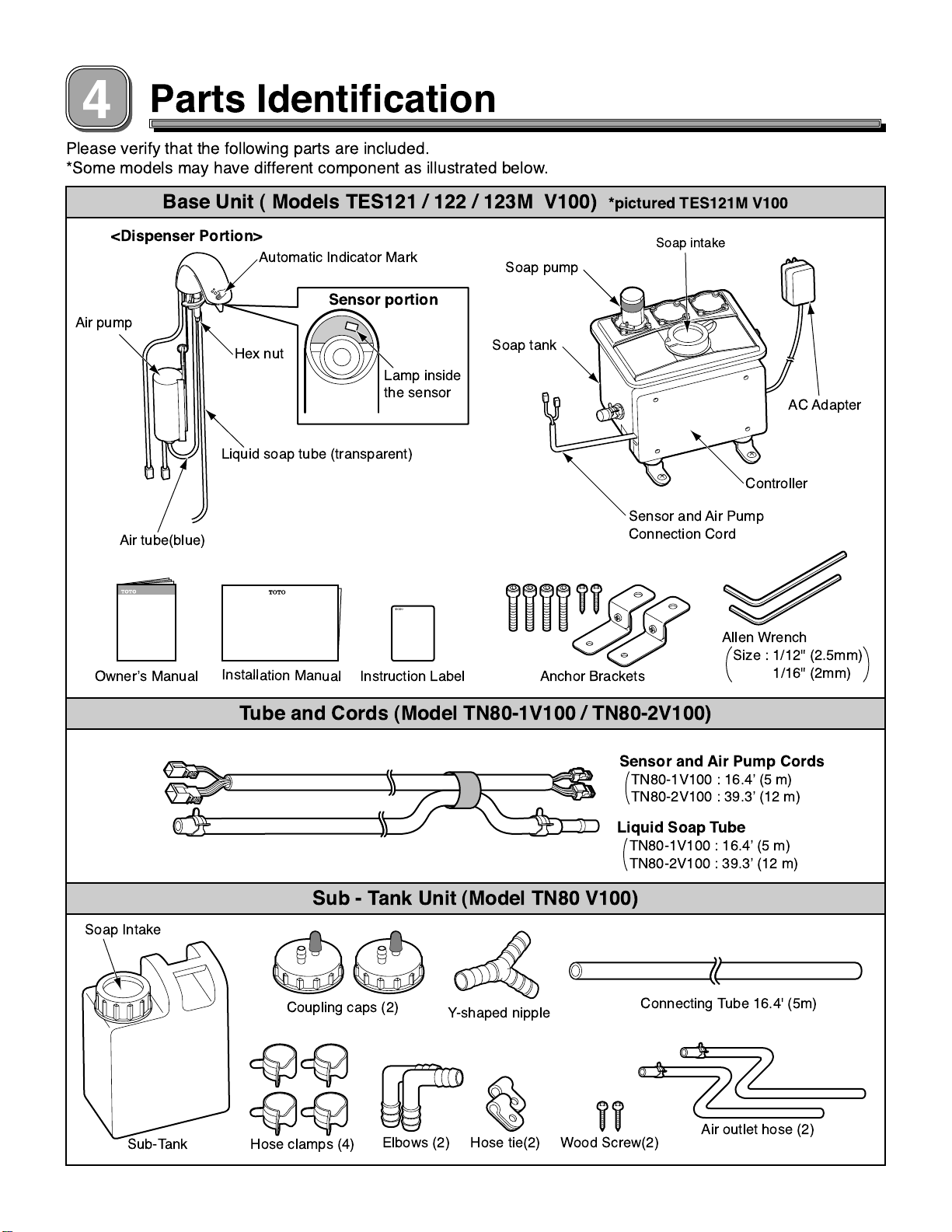
Toto TES4ADC-12 User manual

Automatic Soap Dispenser
TOTO SOAP DISPENSER
Warranty Registration and Inquiry
For product warranty registration, TOTO U.S.A. Inc. recommends online Warranty Registration. Please visit our web site
http://www.totousa.com. If you have questions regarding warranty policy or coverage, please contact TOTO U.S.A. Inc., Customer
Service Department, 1155 Southern Road, Morrow, GA 30260 (888) 295-8134 or (678) 466-1300 when calling from outside of U.S.A.
03670 T1 2009.04
● The following symbols are used to indicate important
safety instructions for the safe and proper use of the
product.
● Each symbol is defined as follows:
For the best results, be sure to read the following installation instructions and use the product only as described in this manual.
Do not apply force or sudden impact to this product, as
this may cause malfunction or leakage.
Doing so could cause product failure or electric shock.
This product should only be serviced, disassembled or
modified by a factory technician to prevent possible
malfunction or electric shock.
Please do not install in a bathing area or humid place.
Doing so could cause fire or electric shock.
Do not use direct current or power source with
improper voltage.
Doing so may cause fire.
Do not use a loose or faulty electrical outlet or plug.
Doing so may cause fire or electrical shock.
Do not apply force or sudden impact to this product, as
this may cause malfunction or leakage.
Be sure to plug the AC adapter all the way into the wall socket
to avoid possible fire or electrical shock. TOTO recommends
that the AC adapter be connected to a GFCI-protected outlet.

Specfications
Item
<Standard>
Configuration
DetailsSpecifications
Number of Dispenser
Base Unit
Sub-Tank
Power Source
Wattage
Detection Range
Ambient Temperature for Use
Power Cord Length
Dispensed Amount of Soap
Tank Capacity
Tube and
Cords
TES1ADC-05
12
N/A
AC Apapter Input : 120VAC60Hz Output : 24VDC
20W10W 30W
4"(110mm) (using #300 white paper )*Note that the detection range may vary due to learning methods.
34~1040F(1~40oC)
71"(1.8m)
TES121M V100
TN80-1 V100
16.4'
(5m)
16.4'
(5m)
TES122M V100
TN80-1 V100(2sets)
16.4'
(5m)
TES123M V100
TN80-1 V100(3sets)
2mL (at factory setting)
Approximately 1 gallon (4L) (Usable Capacity)
3
TES2ADC-05 TES3ADC-05
Item
<Special> … with subtank and 39.4’ (12m) tube and cords
Configuration
DetailsSpecifications
Number of Dispenser
Base Unit
Sub-Tank
Power Source
Wattage
Detection Range
Ambient Temperature for Use
Power Cord Length
Dispensed Amount of Soap
Tank Capacity
Tube and
Cords
TES3ADC-12 TES4ADC-12 TES5ADC-12 TES6ADC-12
3
1set TN80 V100
AC Apapter Input : 120VAC60Hz Output : 24VDC
30W
6.8 gallons (26L) (usable capacity)
4"(110mm) (using #300 white paper )*Note that the detection range may vary due to learning methods.
34~1040F(1~40oC)
71"(1.8m)
39.4'
(12m) 39.4'
(12m) 39.4'
(12m) 39.4'
(12m)
TES123M V100
TN80-2 V100(3sets)
4
40W(20W+20W)
TES122M V100
(2sets)
TN80-2 V100(4sets)
5
50W(20W+30W)
TES122M V100
TES123M V100
TN80-2 V100(5sets)
6
60W(30W+30W)
TES123M V100
(2sets)
TN80-2 V100(6sets)
2mL (at factory setting)
Approximately 8 gallons (30L) (Usable Capacity)

Before Installing Your TOTO Soap Dispenser
1. Wiring
The voltage is AC 120V (60Hz). The energy consumption is as follows.
Wiring should be installed in compliance with the following energy consumption levels.
10W
20W
30W
Single spout configuration : TES1ADC-05
Two spout configuration : TES2ADC-05
Three spout configuration : TES3ADC-05/TES3ADC-12
Four spout configuration : TES4ADC-12 40W (20W+20W)
Five spout configuration : TES5ADC-12 50W (20W+30W)
Six spout configuration : TES6ADC-12 60W (30W+30W)
2. Installation of the soap tank
3. Other
Install the soap tank and sub-tank (Special) on a flat surface.
When connecting the tank or installing the sub-tank (Special), make sure that both tanks are in-
stalled on a flat and level surface. Be sure to install the soap tubes in a straight line.
This product cannot be used with stainless steal or stainless steal plated lavatories, as this may
cause malfunction of the product.
The dispenser installation holes for this product are 1"~ 1-1/8" (25 ~ 28 mm) in diameter.
Be especially careful not to scratch the sensor surface.

Parts Identification
Please verify that the following parts are included.
*Some models may have different component as illustrated below.
Base Unit ( Models TES121 / 122 / 123M V100) *pictured TES121M V100
<Dispenser Portion>
Tube and Cords (Model TN80-1V100 / TN80-2V100)
Sub - Tank Unit (Model TN80 V100)
Sub-Tank
Coupling caps (2)
Elbows (2) Hose tie(2) Wood Screw(2)
Connecting Tube 16.4' (5m)
Y-shaped nipple
Hose clamps (4) Air outlet hose (2)
Lamp inside
the sensor
Air tube(blue)
Liquid soap tube (transparent)
Anchor Brackets
Soap tank
Sensor and Air Pump
Connection Cord
Controller
Hex nut
Automatic Indicator Mark
Sensor portion
Soap pump
AC Adapter
Soap intake
Air pump
Soap Intake
Installation Manual
OwnerÕs Manual Instruction Label
Allen Wrench
Liquid Soap Tube
TN80-1V100 : 16.4Õ (5 m)
TN80-2V100 : 39.3Õ (12 m)
Sensor and Air Pump Cords
TN80-1V100 : 16.4Õ (5 m)
TN80-2V100 : 39.3Õ (12 m)
Size : 1/12" (2.5mm)
1/16" (2mm)

Installation of the Dispenser and Tank
Sink
]
Caution
(1)
(2)
Do not install the liquid soap tubes at a height that is taller than the height of the
counter ven after the unit is
turned off.
(1)
(2)
Standard (TES1/TES2/TES3ADC-05) Within 16.4' (5m)
Special (TES3/TES4/TES5/TES6ADC-12) Within 39.4' (12m)
Position of the Dispenser
Position of the Tank
Auto Soap Dispenser
Water valve
Screw holes for installing the dispenser
[1"
~ 1-1/8" (25 ~ 28mm) in diameter
(2) Tube and cords lengths : 16.4Õ (5m) Standard
39.4Õ (12m) Special
(1) Within 31-1/2"(800mm)
(2) The distance from the soap dispenser
to the edge of the sink = within 3-1/8Ó (80 mm)
(1) Space between the dispenser and the
water valve=more than 4Ó (100mm)
Be sure to leave at least 4Ó (100 mm) of space between the soap dispenser and the watervalve to pre-
vent a malfunction of the detector, which could result in faulty soap spray.
Leave 3-1/8Ó (80 mm) of space from the inside edge of the sink to the spout installationholes to ensure
that any residual soap drips from the dispenser spout into the sink bowl.
Install the liquid soap tank within 31-1/2Ó (800 mm) under the counter.
The tank cannot be installed on top of the counter or underground.
When installing the tank, make sure that the tubes and cords can reach the tank.
, as this may cause the water and soap to discharge e

Diagram of Assembled Product
10-1/4"
(262mm)
28-1/4"
(720mm)
(282mm) 9-1/4"
(234mm)
4-1/4"
1-1/8"
(30mm)
1/4"~1-1/8"
(5~30mm)
Model : TE1SADC-05
11-1/8"
Wall surface
(110mm)
floor surface
*Some models may have different components as illustrated below.

Installation Procedure
1Pre-installation of the dispenser
2Installing the air pump.
3Pre-installation of the tank.
4Connecting the
tubes and cords
(Dispenser Side)
5Connecting the
tubes and cords
(Tank Side)
6Anchor the tank.
7Inserting the AC adapter
8Filling the tank with liquid soap
9Secure the dispenser
(Model TES6ADC-12 shown)
Installation of the Sub-tank (Special)
Caution
Use of the TOTO Soap Dispenser in conjunction with other equipment that has
an inverter or infrared lamps may cause the unit to malfunction.
Make sure that the cords and tubes do not come into contact with the hot water
supply pipe.

1
2
3
Dispenser
Washer
Packing
Caution
Caution
Be sure to place the tank and sub-
(1)
(2)
(1)
(2)
Pre-installation of the dispenser
Installing the air pump
Pre-installation of the tank
Air Pump Hook
Air tube (blue)
Air pump
Hook for the
air pump
Liquid soap tube(transparent)
Air tube (blue)
Sensor cord
Hex nut
Make sure that the cords and tubes do not
get crimped.
tank(Special) on a level surface.
Insert the dispenser into the installation holes in
the counter (or the sink).
Loosely screw in the washers with the hex nuts.
Hook the air pump onto the air pump hook.
Connect the air tube (blue).
Place the tank in the designated position.

4Connecting the tubes and cords (Connection to the Dispenser Side)
Liquid soap tube (white)
Liquid soap tube
(white)
Coupling caps
Connect to the
dispenser side
Connect to the
tank side
Male connector
Secure here with tape
Female connector cords
Preparation before connecting the tubes and cords
Pre-insertion of the connectors
"Click"
Connector for the sensor White
Connector for the air pump Green
Connector for the sensor (white)
Liquid soap tube
(transparent)
Coupling cap
Lock
Connector for the
air pump (green)
Be sure to connect one cord with one liquid soap tube (white).
Before connecting the tubes and cords, pair one liquid soap tube (white) with one cord and
tape them together.
When installing 2 or more dispenser units, make sure to use the same number of tube-cord
pairs as dispenser units to be installed. Improper installation may result in a malfunction of the
dispenser.
Caution
Be sure to insert the tubes all the way
into the coupling caps.
Be sure to insert
the connectors all
the way into place
until they lock
into position.
Be careful not to
damage the wa-
terproof packing
when inserting or
pulling out the
connectors.
Connect each of the connectors for the sensors
and air pump cords.
(1)
Connect the liquid soap tubes.
(Use the coupling caps to connect them.)
Insert the connectors until they
lock into place.
Check to make sure
that the connectors
are not upside down.
Be sure to insert the
connectors straight
into position and not
at an angle.
Not locked into
place.
To pull out the connector, push in
the lock and pull down and out.
(2)
Caution

5Connecting the tubes and cords (Connection to the Tank Side)
6Anchor the tank
Liquid soap tubes (white)
cords
Leveling Bolts
Leveling Bolts
Anchor bracket
Screws
Screws
Anchor
bracket
Clamp
Coupling cap
Liquid soap
tube (white)
White label
White label
Red label
Red label
Green label
Green label
Pair
Pair
Pair
Insert the liquid soap tubes into each of the cou-
pling caps located on the side of the liquid soap
pump and secure them with the clamps.
Connect each of the liquid soap tubes and the
pair of cords with each of the cords on the tank
side that have the same color label as the labels
affixed to the pump. (Three sensor cord cores
and two air pump cord cores.)
Insert into the tube coupling
caps and secure with the
clamps.
(1)
(2)
Insert the four bolts into the bottom of the tank
hand tight.
These bolts will need to be adjusted to level the
tank.
Install the two screws after the tank has been
leveled.
NOTE: If installing on a concrete floor, be sure to
use inserts before installing the two screws.
(1)
(2)
Anchor the tank with the supplied brackets.

7
8
Inserting the AC Adapter
Insert the AC Adapter into the wall outlet.
(red)
Caution
Av
or co o
*The sensor lamp will flash when there
is no soap in the tank.
wn.
Lamp inside
the sensor.
The range detector is activated when
the power is connected.
oid placing objects in the sink bowl
vering the sensor with your hand.
(The range detector is set in appr xi-
mately 10 seconds.)
Do not install AC Adapter upside do
,
DispenserÓ
.
Sub-tank
9
Caution
When the dispenser is not in use f
water and perf
f“
Operation 2.When the Dispenser is Not
”.
Fill the tank with liquid soap.
(If your unit has a sub-tank, pour the liquid soap into
the opening in the sub-tank.)
*Fill the tank until the light located inside the sensor
stops flashing. If the sensor light continues to flash
even after adding 1/2 gallon (2L) of soap, see the in-
structions in the next section
ÒSecuring the
Filling the tank with liquid soap Tank
or long periods of
time, fill the tank with orm a trial Re-
er to
Trial
Used for Long Periods of Time

9
(1)
(2)
Caution
let.
Securing the Dispenser
Two flashes every second means. Liquid soap level is near empty.
Eight flashes every second means. The sink is reflecting off the sensor light, cau-
sing an obstruction.
Lamp inside sensor (red)
Hex nut
Make sure not to cover the sensor light with your hand or place any
objects inside the sink bowl, as this will cause the Lamp inside the
sensor located at the front of the dispenser to flash off and on.
If the light continues to flash even after removing
any obstacles, adjust the position of the dispens-
er until the light stops flashing.
The sensor light flashes in two different modes.
Secure the dispenser with the hex nuts provided. The hex nuts are
positioned 1/2Ó (13mm) apart on opposite sides of the dispenser.
Certain types of ceramic may cause the sensor light
to flash off and on continuously. In this case, follow
the standard installation procedure. The sensor will
automatically recalibrate itself.
Once the unit has been turned on, the light will stop
flashing after 10 minutes.
If the dispenser position is still being adjusted when the flashing light automatically
goes out after 10 minutes, pull the power cord out of the wall outlet and reinsert.
Be sure to wait at least 10 seconds before inserting the plug back into the wall out-
If installation is not completed before sensor is calibrated.

Trial Operation
(1)
(2)
Caution
1. Confirming that the dispenser functions properly after installation
After installation is complete, confirm that the unit is working properly using the following method.
Place your hands under the dispenser spout and hold them in place until soap is discharged.
Make sure that there is no soap leaking from the tube and hose connections.
The dispenser pump will operate intermittently. After
the third discharge, the dispenser will operate contin-
uously for a maximum of 4 minutes.
Continuous discharge only takes place within 15 min-
utes following power ON.
2. When the dispenser is not in use for long periods of time
If the dispenser is not in use for an extended period of time, the liquid soap in the tube may
waterdry up and clog the tube. In such a case, fill the dispenser tank with and perform a tri-
al operation. Once you have confirmed that the dispenser is working properly, replace the
water in the tank with liquid soap.
3. Confirming proper operation
Starting and stopping the soap discharge.
Hold your hands under the dispenser spout to automatically discharge soap foam.
Remove your hands from under the spout and the dispenser will stop pumping soap.
Hold your hands under the spout continuously and an intermittent discharge of soap is pumped (a maxi-
mum of 3 discharges over a two-second period).
4. Trouble shoting
Phenomenon
What to look for What to do
Reference page
No soap
comes out.
It doesn't
dispense
mousse.
Hardly
any soap
comes out.
7
8
,
4 5
,
4 5
,
4 5
2
Is the AC adapter inserted in the electrical outlet?
The AC adapter is inserted.
Fill the tank with liquid soap.
Insert tube.
Insert the white connector.
Remove the knik.
Insert the green connector.
Please use the recomme-
nded liquid soap.
Insert the blue air tube all
the way into place
Instruction manual
Does the liquid soap tank contain liquid soap?
Is the soap tube inserted securely?
Is the white connector inserted securely?
Is there a kink in the tube?
Is the green connector for the air pump inserted securely?
Are you using a high-viscosity liquid soap?
Is the blue air tube pushed all the way into place?
A bent hose is corrected.
Hasn't the connected hose of the sub tank and
the water soap tank bent?

Installation of the Sub-Tank (Special)
Coupling cap
Air deflation hose
hose clamp
Hose clamp
Connection
hose
Air deflation hose
Sub-tank supply
Sub-Tank
Elbow
Tank
Connection
hose
Coupling Cap
Sub-tank
Cap Hose clamp
Connection hose
Connect the hose to the sub-tank.(1)
Remove the cap located on the side of the tank.(2)
Connect one end of the connection hose to the cou-
pling cap on the side of the liquid soap tank.
(3)
Unscrew and remove the lid for the soap tank sup-
ply opening and replace it with the coupling cap.
Connect the air deflation hose to the coupling on the
coupling cap and secure with hose clamp.
(4)
* Use the connection hose for connecting the liquid
soap tanks and cut to the desired length to fit be-
tween the sub-tank and the tank.
Fill the sub-tank with liquid soap from the sub-tank supply opening.
Caution
Be sure to tighten the hose connection with
the hose clamp to secure it into place.
Caution
If the cap is not replaced soap will overflow
in this area.
Caution
Do not have kinks or excessive bends in the
hose.

(5) Attach the elbow to the front end of the air deflation
hose and attach it to the wall with the hose tie and
wood screw.
*Do not block the elbow. It is the air bleed point for
the system. The soap will not flow properly if the el-
bow is blocked.
Elbow
Air
Wood Screw
Hose tie
Air delflation hose
Be sure to install the elbow between the top of the
sub-tank and the counter.
When the elbow is installed lower than the sub
tank the soap overflows.
Be sure that the hose tie is in position with the air
deflation hose and the elbow.
Caution
The total length of the connection hose is
16.4’(5 m).
’(5 m).
liquid soap.
To ensure sufficient supply performance, do
not use a hose that is longer than 16.4
Please install the hose horizontally.
(It is OK to place on the floor.)
Install the hose in a straight line.
A bent hose will prevent the smooth flow of
Position the tanks on a level surface at even
height. Installing the tanks at different levels
may result in the following malfunctions:
Soap leakage from the tank that is at a low-
er level.
Improper detection of the liquid soap level
in the tank at the higher level.

Connecting two liquid soap tanks to one sub-tank
Be sure to provide the customer with the Owner's Manual, Instruction Label, and
Allen wrenches that come with the TOTO Soap Dispenser.
Connection hose
Connection hose
Y-shaped nipple
Up to two liquid soap tanks can be connected to one sub-tank. Attach the Y-shaped nipple
to sub-tank to divert the connection hoses and connect them to each of the liquid soap
tanks.
Caution
Hose length max 16.4’(5m)
This manual suits for next models
6
Table of contents
Other Toto Dispenser manuals

Toto
Toto TES100DA Installation instructions

Toto
Toto EGO TX728AE User manual

Toto
Toto DSE101EEB Installation instructions

Toto
Toto TLK03001G Installation instructions

Toto
Toto DSE102E User manual

Toto
Toto TLK02001 Series User manual

Toto
Toto DSE101E User manual

Toto
Toto TS126AR User manual

Toto
Toto DSE102E User manual

Toto
Toto TLK01103 Series User manual
Popular Dispenser manuals by other brands

diversey
diversey IntelliCare quick start guide

dosatron
dosatron D3 Series owner's manual

Sanela
Sanela Intra SLU 45M5 Instructions for use

Cornelius
Cornelius Bubble Installation, operation & service manual

Bunn
Bunn Ultra NX Installation & operating guide

ASEPT
ASEPT Hovicon International 921020 quick start guide