TQ TQMx120 User manual

User's Manual l TQMx120 UM 0100 l © 2023, TQ-Systems GmbH Page i
TQMx120
User's Manual
TQMx120 UM 0100
21.03.2023

User's Manual l TQMx120 UM 0100 l © 2023, TQ-Systems GmbH Page i
TABLE OF CONTENTS
1. ABOUT THIS MANUAL..............................................................................................................................................................................4
1.1 Copyright and License Expenses.........................................................................................................................................................4
1.2 Registered Trademarks............................................................................................................................................................................4
1.3 Disclaimer.....................................................................................................................................................................................................4
1.4 Imprint...........................................................................................................................................................................................................4
1.5 Service and Support .................................................................................................................................................................................4
1.6 Tips on Safety..............................................................................................................................................................................................5
1.7 Symbols and Typographic Conventions...........................................................................................................................................5
1.8 Handling and ESD Tips ............................................................................................................................................................................5
1.9 Naming of Signals .....................................................................................................................................................................................6
1.10 Further Applicable Documents / Presumed Knowledge............................................................................................................6
2. INTRODUCTION..........................................................................................................................................................................................7
2.1 Overview.......................................................................................................................................................................................................7
2.2 Compliance..................................................................................................................................................................................................8
2.3 Versions.........................................................................................................................................................................................................9
2.4 Accessories................................................................................................................................................................................................ 12
3. FUNCTION ................................................................................................................................................................................................. 13
3.1 Block Diagram.......................................................................................................................................................................................... 13
3.2 Electrical Characteristics ...................................................................................................................................................................... 13
3.2.1 Supply Voltage ........................................................................................................................................................................................ 13
3.2.2 Power Consumption ............................................................................................................................................................................. 14
3.2.3Real Time Clock Power Consumption............................................................................................................................................. 16
3.3 Environmental Conditions .................................................................................................................................................................. 16
3.4 System Components............................................................................................................................................................................. 17
3.4.1 Processor ................................................................................................................................................................................................... 17
3.4.1.1 Intel®Turbo Boost Technology ......................................................................................................................................................... 19
3.4.1.2 Intel®Configurable Thermal Design Power.................................................................................................................................. 19
3.4.2 Graphics ..................................................................................................................................................................................................... 19
3.4.3 Chipset........................................................................................................................................................................................................ 19
3.4.4 Memory...................................................................................................................................................................................................... 20
3.4.4.1 DDR5 SDRAM SO-DIMM....................................................................................................................................................................... 20
3.4.4.2 SPI Boot Flash........................................................................................................................................................................................... 20
3.4.4.3SPI General Purpose .............................................................................................................................................................................. 20
3.4.4.4 EEPROM...................................................................................................................................................................................................... 20
3.4.5 Real Time Clock ....................................................................................................................................................................................... 21
3.4.6 Trusted Platform Module..................................................................................................................................................................... 21
3.4.7 Hardware Monitor.................................................................................................................................................................................. 21
3.4.8 TQ Flexible I/O Configuration (TQ-flexiCFG)................................................................................................................................. 21
3.5 Interfaces ................................................................................................................................................................................................... 22
3.5.1 PCI Express ................................................................................................................................................................................................ 22
3.5.2 PCI Express Graphics (PEG-Port)........................................................................................................................................................ 22
3.5.3 2.5 Gigabit Ethernet............................................................................................................................................................................... 23
3.5.4 Serial ATA................................................................................................................................................................................................... 23
3.5.5 Digital Display Interface....................................................................................................................................................................... 23
3.5.6 LVDS / eDP Interface.............................................................................................................................................................................. 23
3.5.7 USB 2.0 and USB 3.2 Interfaces .......................................................................................................................................................... 24
3.5.8 USB4 interface ......................................................................................................................................................................................... 24
3.5.9 General Purpose Input / Output ....................................................................................................................................................... 24
3.5.10 High Definition Audio Interface ........................................................................................................................................................ 24
3.5.11 LPC / eSPI Bus........................................................................................................................................................................................... 25
3.5.12 I2C Bus ......................................................................................................................................................................................................... 25
3.5.13 SMBus ......................................................................................................................................................................................................... 25
3.5.14 MIPI-CSI Camera Serial Interface....................................................................................................................................................... 25
3.5.15 Serial Ports................................................................................................................................................................................................. 26
3.5.16 Watchdog Timer ..................................................................................................................................................................................... 26
3.6 Connectors................................................................................................................................................................................................ 27
3.6.1 ................................................................................................................................................................... 27
3.6.2 Debug Header ......................................................................................................................................................................................... 27
3.6.3 TQM Debug Card.................................................................................................................................................................................... 28
3.6.4 Debug Module LED................................................................................................................................................................................ 28
3.7 ..................................................................................................................................................... 29
3.7.1 Signal Assignment Abbreviations .................................................................................................................................................... 29

User's Manual l TQMx120 UM 0100 l © 2023, TQ-Systems GmbH Page ii
3.7.2 ................................................................................................................................... 30
4. MECHANICS .............................................................................................................................................................................................. 38
4.1 Dimensions ............................................................................................................................................................................................... 38
4.2 Component Placement and Labels.................................................................................................................................................. 39
4.3 Heat Spreader .......................................................................................................................................................................................... 40
4.4 Mechanical and Thermal Considerations ...................................................................................................................................... 40
4.5 Protection against External Effects .................................................................................................................................................. 40
5. SOFTWARE ................................................................................................................................................................................................ 41
5.1 System Resources................................................................................................................................................................................... 41
5.1.1 I2C Bus Devices......................................................................................................................................................................................... 41
5.1.2 SMBus Devices......................................................................................................................................................................................... 41
5.1.3 Memory Mapping................................................................................................................................................................................... 41
5.1.4 Interrupt Mapping.................................................................................................................................................................................. 41
5.2 Operating Systems................................................................................................................................................................................. 42
5.2.1 Supported Operating Systems .......................................................................................................................................................... 42
5.2.2 Driver Download..................................................................................................................................................................................... 42
5.3 TQ-Systems Embedded Application Programming Interface (EAPI)................................................................................... 42
5.4 Software Tools ......................................................................................................................................................................................... 42
6. BIOS MENU ............................................................................................................................................................................................ 43
6.1 Continue .................................................................................................................................................................................................... 43
6.2 Boot Manager .......................................................................................................................................................................................... 43
6.3 Device Manager ...................................................................................................................................................................................... 44
6.3.1 Driver Health Manager ......................................................................................................................................................................... 44
6.3.2 Network Device List............................................................................................................................................................................... 44
6.4 Boot from File........................................................................................................................................................................................... 44
6.5 Administer Secure Boot ....................................................................................................................................................................... 44
6.6 Setup Utility.............................................................................................................................................................................................. 45
6.6.1 Main............................................................................................................................................................................................................. 45
7. BIOS UPDATE ........................................................................................................................................................................................ 46
7.1.1 Step 1: Preparing USB Stick................................................................................................................................................................. 46
7.1.2 Step 2: Preparing Management Engine (ME) FW for update.................................................................................................. 46
7.1.3 Step 3a: Updating uEFI BIOS via EFI Shell ...................................................................................................................................... 48
7.1.4 Step 3b: Updating uEFI BIOS via Windows Operating System .............................................................................................. 49
7.1.5 Step 4: BIOS update check on the TQMx120 Module ............................................................................................................... 49
8. SAFETY REQUIREMENTS AND PROTECTIVE REGULATIONS..................................................................................................... 50
8.1 EMC.............................................................................................................................................................................................................. 50
8.2 ESD............................................................................................................................................................................................................... 50
8.3 Shock & Vibration ................................................................................................................................................................................... 50
8.4 Operational Safety and Personal Security ..................................................................................................................................... 50
8.5 Reliability and Service Life................................................................................................................................................................... 50
8.5.1 RoHS ............................................................................................................................................................................................................ 50
8.5.2 WEEE®......................................................................................................................................................................................................... 50
8.6 REACH®....................................................................................................................................................................................................... 50
8.7 EuP ............................................................................................................................................................................................................... 50
8.8 Battery ........................................................................................................................................................................................................ 50
8.9 Packaging.................................................................................................................................................................................................. 50
8.10 Other Entries............................................................................................................................................................................................. 51
9. APPENDIX .................................................................................................................................................................................................. 52
9.1 Acronyms and Definitions................................................................................................................................................................... 52
9.2 References................................................................................................................................................................................................. 54
User's Manual l TQMx120 UM 0100 l © 2023, TQ-Systems GmbH Page iii
TABLE DIRECTORY
Table 1: Terms and Conventions...................................................................................................................................................................5
Table 2: .................................9
Table 3: .............................. 10
Table 4: .............................. 11
Table 5: TQMx120 Power Consumption Turbo Mode ON .............................................................................................................. 15
Table 6: TQMx120 Power Consumption Turbo Mode OFF............................................................................................................. 15
Table 7: RTC Current Consumption .......................................................................................................................................................... 16
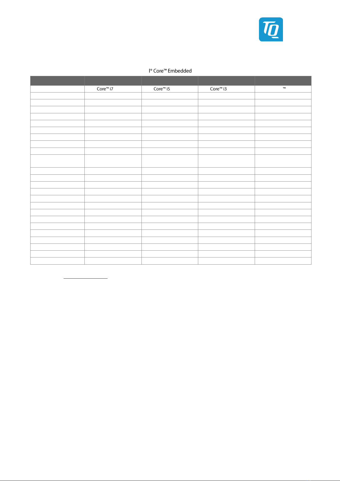
Table 8: 12th Generation Intel®-Series............................................................................................ 17
Table 9: 12th Generation Intel®-Series ............................................................................................ 18
Table 10: 12th Generation Intel®-Series............................................................................................ 18
Table 11: Maximum Resolution Display Configuration........................................................................................................................ 19
Table 12: PCI Express port 0 7 Configuration Options ...................................................................................................................... 22
Table 13: PCI Express Graphics port Configuration Options .............................................................................................................. 22
Table 14: ................................................................................................................................ 26
Table 15: LED Boot Messages ........................................................................................................................................................................ 28
Table 16: Signal Assignment Abbreviations............................................................................................................................................. 29
Table 17: ........................................................................................................................... 30
Table 18: Labels on TQMx120........................................................................................................................................................................ 39
Table 19: I2 2C Port....................................................................................................................... 41
Table 20: I2............................................................................................................... 41
Table 21: Acronyms........................................................................................................................................................................................... 52
Table 22: Further Applicable Documents and Links ............................................................................................................................. 54
FIGURE DIRECTORY
Figure 1: TQMx120 block diagram .............................................................................................................................................................. 13
Figure 2: TQM Debug Card ............................................................................................................................................................................ 28
Figure 3: Debug Module LED ........................................................................................................................................................................ 28
Figure 4: TQMx120 three view drawing.................................................................................................................................................... 38
Figure 5: TQMx120 Bottom View Drawing............................................................................................................................................... 38
Figure 6: TQMx120 Component Placement Top ................................................................................................................................... 39
Figure 7: TQMx120 Component Placement Bottom............................................................................................................................ 39
Figure 8: TQMx120-HSP Heat Spreader..................................................................................................................................................... 40
Figure 9: InsydeH2O BIOS Front Page........................................................................................................................................................ 43
Figure 10: PCH-FW Configuration menu..................................................................................................................................................... 47
Figure 11: Firmware Update Configuration menu .................................................................................................................................. 47
Figure 12: ME FW Image Re-Flash option ................................................................................................................................................... 47
Figure 13: EFI Shell............................................................................................................................................................................................... 48
Figure 14: EFI Shell uEFI BIOS Update .......................................................................................................................................................... 48
Figure 15: Screen during BIOS Update......................................................................................................................................................... 48
Figure 16: TQMx120 Debug LED .................................................................................................................................................................... 49
Figure 17: EFI BIOS Main Menu ....................................................................................................................................................................... 49
REVISION HISTORY
Rev.
Date
Name
Pos.
Modification
0100
21.03.2023
KG
First release

User's Manual l TQMx120 UM 0100 l © 2023, TQ-Systems GmbH Page 4
1. ABOUT THIS MANUAL
1.1 Copyright and License Expenses
Copyright protected © 2023 by TQ-Systems GmbH.
This User's Manual may not be copied, reproduced, translated, changed or distributed, completely or partially in electronic,
machine readable, or in any other form without the written consent of TQ-Systems GmbH.
The drivers and utilities for the components used as well as the BIOS are subject to copyrights of the respective manufacturers.
The licence conditions of the respective manufacturer are to be adhered to.
BIOS-licence expenses are paid by TQ-Systems GmbH and are included in the price.
Licence expenses for the operating system and applications are not taken into consideration and have to be calculated/declared
separately.
1.2 Registered Trademarks
TQ-Systems GmbH aims to adhere to copyrights of all graphics and texts used in all publications, and strives to use original
or license-free graphics and texts.
All brand names and trademarks mentioned in this User's Manual, including those protected by a third party, unless specified
otherwise in writing, are subjected to the specifications of the current copyright laws and the proprietary laws of the present
registered proprietor without any limitation. One should conclude that brand and trademarks are rightly protected by
a third party.
1.3 Disclaimer
TQ-Systems GmbH does not guarantee that the information in this User's Manual is up-to-date, correct, complete or of good
quality. Nor does TQ-Systems GmbH assume guarantee for further usage of the information. Liability claims against
TQ-Systems GmbH, referring to material or non-material related damages caused, due to usage or non-usage of the information
given in this User's Manual, or due to usage of erroneous or incomplete information, are exempted, as long as there is no proven
intentional or negligent fault of TQ-Systems GmbH.
TQ-Systems GmbH explicitly reserves the rights to change or add to the contents of this User's Manual or parts of it without
special notification.
1.4 Imprint
TQ-Systems GmbH
Gut Delling, Mühlstraße 2
D-82229 Seefeld
Tel: +49 8153 9308 0
Fax: +49 8153 9308 4223
E-Mail: Info@TQ-Group
Web: TQ-Group
1.5 Service and Support
Please visit our website www.tq-group.com for latest product documentation, drivers, utilities and technical support.
You can register on our website www.tq-group.com to have access to restricted information and automatic update services.
Our FAE team can also support you with additional information like 3D-STEP files and confidential information, which is not
provided on our public website.
For service/RMA, please contact our service team by email ([email protected]) or your sales team at TQ-Systems GmbH.
User's Manual l TQMx120 UM 0100 l © 2023, TQ-Systems GmbH Page 5
1.6 Tips on Safety
Improper or incorrect handling of the product can substantially reduce its life span.
1.7 Symbols and Typographic Conventions
Table 1: Terms and Conventions
Symbol
Meaning
This symbol represents the handling of electrostatic-sensitive modules and / or components. These
components are often damaged / destroyed by the transmission of a voltage higher than about 50 V.
A human body usually only experiences electrostatic discharges above approximately 3,000 V.
This symbol indicates the possible use of voltages higher than 24 V.
Please note the relevant statutory regulations in this regard.
Non-compliance with these regulations can lead to serious damage to your health and also cause
damage / destruction of the component.
This symbol indicates a possible source of danger. Acting against the procedure described can lead to
possible damage to your health and / or cause damage / destruction of the material used.
This symbol represents important details or aspects for working with TQ-products.
Command
A font with fixed-width is used to denote commands, contents, file names, or menu items.
1.8 Handling and ESD Tips
General handling of your TQ-products
The TQ-product may only be used and serviced by certified personnel who have taken note of the
information, the safety regulations in this document and all related rules and regulations.
A general rule is: do not touch the TQ-product during operation. This is especially important when
switching on, changing jumper settings or connecting other devices without ensuring beforehand
that the power supply of the system has been switched off.
Violation of this guideline may result in damage / destruction of the TQMx120 and be dangerous
to your health.
Improper handling of your TQ-product would render the guarantee invalid.
Proper ESD handling
The electronic components of your TQ-product are sensitive to electrostatic discharge (ESD).
Always wear antistatic clothing, use ESD-safe tools, packing materials etc., and operate your TQ-
product in an ESD-safe environment. Especially when you switch modules on, change jumper settings,
or connect other devices.

User's Manual l TQMx120 UM 0100 l © 2023, TQ-Systems GmbH Page 6
1.9 Naming of Signals
A hash mark (#) at the end of the signal name indicates a low-active signal.
Example: RESET#
If a signal can switch between two functions and if this is noted in the name of the signal, the low-active function is marked
with a hash mark and shown at the end.
Example: C / D#
If a signal has multiple functions, the individual functions are separated by slashes when they are important for the wiring.
The identification of the individual functions follows the above conventions.
Example: WE2# / OE#
1.10 Further Applicable Documents / Presumed Knowledge
•Specifications and manual of the modules used:
These documents describe the service, functionality and special characteristics of the module used.
•Specifications of the components used:
The manufacturer's specifications of the components used, for example CompactFlash cards, are to be taken note of.
They contain, if applicable, additional information that has to be taken note of for safe and reliable operation.
These documents are stored at TQ-Systems GmbH.
•Chip errata:
It is the user's responsibility to make sure all errata published by the manufacturer of each component are taken note of.
•Software behaviour:
No warranty can be given, nor responsibility taken for any unexpected software behaviour due to deficient components.
•General expertise:
Expertise in electrical engineering / computer engineering is required for the installation and the use of the device.
Implementation information for the carrier board (3), maintained by the
PICMG®. This Carrier Design Guide includes a very good guideline to desi
It includes detailed information with schematics and detailed layout guidelines.
Please refer to the official PICMG®documentation for additional information (2), (4).
User's Manual l TQMx120 UM 0100 l © 2023, TQ-Systems GmbH Page 7
2. INTRODUCTION
Based on the internationally established PICMG®(COM.0 Rev. 3.1), the TQMx120 enables the design of
not only powerful but also economical x86 based systems. The user has access to all essential interfaces of the CPU at the Type 6
compliant pin out connector. Hence all features of the 12th Generation Intel®can be used. The direct access to all
interfaces gives the user the freedom to use the features of the CPU in the most suitable way for his application.
The compact and robust design as well as the option of conformal coating extends the use cases to applications within rugged
industry, transportation and aviation environments. Based on the very low-power consumption and the extended temperature
support it is also possible to realize outdoor applications in an easy and reliable way.
2.1 Overview
The following key functions are implemented on the TQMx120:
Processor:
12th Generation Inte embedded H-series (Alder Lake-P / H45) with up to 14 processor cores
•Intel®i7-12800HE 6P+8E / 96EU, 24 MB Cache, up to 4.6 GHz , 45 W (cTDP 35 W), 0 °C 100 °C
•Intel®i5-12600HE 4P+8E / 80EU, 18 MB Cache, up to 4.5 GHz , 45 W (cTDP 35 W), 0 °C 100 °C
•Intel®i3-12300HE 4P+4E / 48EU, 12 MB Cache, up to 4.3 GHz , 45 W (cTDP 35 W), 0 °C 100 °C
12th Generation Inte P-series (Alder Lake-P / P28) with up to 12 processor cores
•Intel®i7-1270PE 4P+8E / 96EU, 18 MB Cache, up to 4.5 GHz , 28 W (cTDP 35 W / 20 W), 0 °C 100 °C
•Intel®i5-1250PE 4P+8E / 80EU, 12 MB Cache, up to 4.4 GHz , 28 W (cTDP 35 W / 20 W), 0 °C 100 °C
•Intel®i3-1220PE 4P+4E / 48EU, 12 MB Cache, up to 4.2 GHz , 28 W (cTDP 35 W / 20 W), 0 °C 100 °C
12th Generation Inte U-series (Alder Lake-P / U15) with up to 10 processor cores
•Intel®i7-1265UE 2P+8E / 96EU, 12 MB Cache, up to 4.7GHz , 15 W (cTDP 28 W / 12 W), 0 °C 100 °C
•Intel®i5-1245UE 2P+8E / 80EU, 12 MB Cache, up to 4.4 GHz , 15 W (cTDP 28 W / 12 W), 0 °C 100 °C
•Intel®Cor i3-1215UE 2P+4E / 64EU, 10 MB Cache, up to 4.4 GHz , 15 W (cTDP 28 W / 12 W), 0 °C 100 °C
•Intel®7305E 1P+4E / 48EU, 8 MB Cache, up to 0.9 GHz , 15 W (cTDP 12 W), 0 °C 100 °C
Memory:
•2 × DDR5 SO-DIMM socket with max. 64 Gbyte, dual channel DDR5 up to 4800 MT/s SO-DIMM modules
•EEPROM: 32 kbit (24AA32) (optional)
Graphics:
•3 × Digital Display Interface / DP++ with up to 8K; DisplayPort 1.4a with support for Multi-Stream Transport (MST)
•1 × Embedded Digital Display Interface (eDP) or dual channel LVDS interface (eDP 1.4b or dual LVDS)
Peripheral interfaces:
•1 × 2.5 Gigabit Ethernet (Intel®i226)
•4 × USB 3.2 Gen 2 (up to 10 Gb/s) with USB 3.0 compatibility
•2 × USB4 Support, pins shared with Digital Display Interface (optional)
•8 × USB 2.0
•2 × SATA Gen 3 (up to 6 Gb/s) or 2x PCIe Gen 3 (up to 8 Gb/s)
•4 × PCIe Gen 3 (up to 8 Gb/s) (4 (×1), 2 (×2), or 1 (×4))
•4 × PCIe Gen 4 (up to 16 Gb/s) (1 (×1), 1 (×2), or 1 (×4))
•1 × PCIe PEG port Gen 4 (up to 16 Gb/s) (1 (×4) and 1 (x8) H series only)
•1 × LPC or eSPI bus
•1 × Intel®HD audio (HDA)
•1 × I2C (2nd I2C optional) (master/slave capable)
•1 × SMBus
•1 × SPI for external uEFI BIOS flash
•1 × SPI general purpose interface (optional)
•2 × Serial port (Rx/Tx, legacy compatible), 4-wire (Rx/Tx/RTS/CTS) optionally through TQ-flexiCFG
•8 × GPIO through TQ-flexiCFG
•1 × MIPI-CSI Camera input interface connector (option)

User's Manual l TQMx120 UM 0100 l © 2023, TQ-Systems GmbH Page 8
Security components:
•TPM discrete SLB9670 TPM 2.0 controller or internal firmware TPM (FTPM)
Others:
•TQMx86 board controller with Watchdog and TQ-flexiCFG
•Hardware monitor
Power supply voltage:
•Wide input: 8.5 V to 20 V maximum input ripple: ±100 mV (U and P processor series)
•Standard input: nominal voltage 12 V (11.4 V to 12.6 V) (H processor series)
•5 V Standby (optional) 5 V (4.75 V to 5.25 V)
•3 V Battery for RTC
Environment:
•Operating Standard temperature: 0 °C to +60 °C
•Operating Extended temperature: 0 °C to +75 °C
•Storage temperature: 40 °C to +85 °C
•Relative humidity (operation): 10 % to 90 % (non-condensing)
•Relative humidity (storage): 5 % to 95 % (non-condensing, with conformal coating)
Form factor / dimensions:
•COMExpress Compact, Type 6, 95 × 95 mm2
2.2 Compliance
The TQMx120 complies with PICMG®e Base Specification (COM.0 Rev. 3.1).

User's Manual l TQMx120 UM 0100 l © 2023, TQ-Systems GmbH Page 9
2.3 Versions
The TQMx120 is available in several standard configurations.
Table 2: TQMx120HC 12th Generation Inte Series configurations and features
Feature
TQMx120HC-AA
TQMx120HC-AB
TQMx120HC-AC
Intel
i7-12800HE
i5-12600HE
i3-12300HE
CPU
6P + 8E
4P + 8E
4P + 4E
CPU TDP
45 / 35 W
45 / 35 W
45 / 35 W
CPU Clock (Base)
2.4 GHz
2.5 GHz
1.9 GHz
GfX
96 EU
80 EU
48 EU
L2 Cache
24 MB
18 MB
12 MB
Heat spreader
TQMx120-HSP-AA
TQMx120-HSP-AA
TQMx120-HSP-AA
Heatsink incl. fan
TQMx120-KK-AA
TQMx120-KK-AA
TQMx120-KK-AA
DRAM / SO-DIMM
16 / 32 / 64 GB
16 / 32 / 64 GB
16 / 32 / 64 GB
Use Condition
Embedded
Embedded
Embedded
Operating Temperature
0 °C to +60 °C (Turbo ON)
0 °C to +75 °C (35 W Turbo OFF)
0 °C to +60 °C (Turbo ON)
0 °C to +75 °C (35 W Turbo OFF)
0 °C to +60 °C (Turbo ON)
0 °C to +75 °C (35 W Turbo OFF)
TPM 2.0
1
1
1
Independent displays
4
4
4
LVDS or eDP
1
1
1
DP or HDMI
3
3
3
2.5 GbE
1
1
1
USB 2.0 host
8
8
8
USB 3.2 host
4
4
4
SATA Gen 3
2
2
2
PCIe Gen 3 ×1
8
8
8
PEG Gen 4 x4 / x8
1 / 1
1 / 1
1 / 1
I2C / SPI
1 / 1
1 / 1
1 / 1
HDA
1
1
1
LPC or eSPI
1
1
1
UART / GPIO
2 / 8
2 / 8
2 / 8
User's Manual l TQMx120 UM 0100 l © 2023, TQ-Systems GmbH Page 10
Table 3: TQMx120PC 12th Generation Inte Series configurations and features
Feature
TQMx120PC-AA
TQMx120PC-AB
TQMx120PC-AC
Intel
-1270PE
-1250PE
-1220PE
CPU
4P + 8E
4P + 8E
4P + 4E
CPU TDP
28 / 35 / 20 W
28 / 35 / 20 W
28 / 35 / 20 W
CPU Clock (Base)
1.8 GHz
1.7 GHz
1.5 GHz
GfX
96 EU
80 EU
48 EU
L2 Cache
18 MB
12 MB
12 MB
Heat spreader
TQMx120-HSP-AA
TQMx120-HSP-AA
TQMx120-HSP-AA
Heatsink incl. fan
TQMx120-KK-AA
TQMx120-KK-AA
TQMx120-KK-AA
DRAM / SO-DIMM
16 / 32 / 64 GB
16 / 32 / 64 GB
16 / 32 / 64 GB
Use Condition
Embedded
Embedded
Embedded
Operating Temperature
0 °C to +60 °C (Turbo ON)
0 °C to +75 °C (Turbo OFF)
0 °C to +60 °C (Turbo ON)
0 °C to +75 °C (Turbo OFF)
0 °C to +60 °C (Turbo ON)
0 °C to +75 °C (Turbo OFF)
TPM 2.0
1
1
1
Independent displays
4
4
4
LVDS or eDP
1
1
1
DP or HDMI
3
3
3
2.5 GbE
1
1
1
USB 2.0 host
8
8
8
USB 3.2 host
4
4
4
SATA Gen 3
2
2
2
PCIe Gen 3 ×1
8
8
8
PEG Gen 4 x4 / x8
1 / --
1 / --
1 / --
I2C / SPI
1 / 1
1 / 1
1 / 1
HDA
1
1
1
LPC or eSPI
1
1
1
UART / GPIO
2 / 8
2 / 8
2 / 8
User's Manual l TQMx120 UM 0100 l © 2023, TQ-Systems GmbH Page 11
Table 4: TQMx120UC 12th Generation Inte Series configurations and features
Feature
TQMx120UC-AA
TQMx120UC-AB
TQMx120UC-AC
TQMx120UC-AD
Intel
-1265UE
-1245UE
-1215UE
Celeron 7305E
CPU
2P + 8E
2P + 8E
2P + 4E
1P + 4E
CPU TDP
15 / 28 / 12 W
15 / 28 / 12 W
15 / 28 / 12 W
15 / 12 W
CPU Clock (Base)
1.7 GHz
1.5 GHz
1.2 GHz
1.0 GHz
GfX
96 EU
80 EU
64 EU
48 EU
L2 Cache
12 MB
12 MB
10 MB
8 MB
Heat spreader
TQMx120-HSP-AA
TQMx120-HSP-AA
TQMx120-HSP-AA
TQMx120-HSP-AA
Heatsink incl. fan
TQMx120-KK-AA
TQMx120-KK-AA
TQMx120-KK-AA
TQMx120-KK-AA
DRAM / SO-DIMM
16 / 32 / 64 GB
16 / 32 / 64 GB
16 / 32 / 64 GB
16 / 32 / 64 GB
Use Condition
Embedded
Embedded
Embedded
Embedded
Operating Temperature
0 °C to +60 °C (Turbo ON)
0 °C to +75 °C (Turbo OFF)
0 °C to +60 °C (Turbo ON)
0 °C to +75 °C (Turbo OFF)
0 °C to +60 °C (Turbo ON)
0 °C to +75 °C (Turbo OFF)
0 °C to +60 °C (Turbo ON)
0 °C to +75 °C (Turbo OFF)
TPM 2.0
1
1
1
--
Independent displays
3
3
3
3
LVDS or eDP
1
1
1
1
DP or HDMI
2
2
2
2
2.5 GbE
1
1
1
1
USB 2.0 host
8
8
8
8
USB 3.2 host
4
4
4
4
SATA Gen 3
2
2
2
2
PCIe Gen 3 ×1
8
8
8
8
PEG Gen 4 x4 / x8
1 / --
1 / --
1 / --
1 / --
I2C / SPI
1 / 1
1 / 1
1 / 1
1 / 1
HDA
1
1
1
1
LPC or eSPI
1
1
1
1
UART / GPIO
2 / 8
2 / 8
2 / 8
2 / 8
Please refer to www.tq-group.com/ for a full list of standard versions.
Other configurations are available on request.
Hardware and software configuration features on request:
•Conformal coating
•Customized BIOS
•USB4 support
•SPI general purpose support

User's Manual l TQMx120 UM 0100 l © 2023, TQ-Systems GmbH Page 12
2.4 Accessories
•TQMx120-HSP
ALU Heat spreader with copper inlay for TQMx120,
•Evaluation platform MB-COME6-4
and Compact, Type 6, 170 × 170 mm2, with the following interfaces:
- 3 × DP (2x up to 8k HBR3, 1x up to 4k HBR2)
- 1 x dual LVDS
- 1 x eDP (up to 4k HBR2)
- 2 × 2.5 Gbit Ethernet
- 2 x USB 3.2 USB-A
- 1 x USB 3.2 USB-C
- 3 x USB 2.0 internal
- 2 × Serial Port RS232
- 1x High Definition Audio (Line In, MIC In, HP Out)
- 1x M.2 Socket Key E (Wi-Fi/BT),
- 1x M.2 Socket Key B with µSIM (WWAN or SATA SSD)
- 1x M.2 Socket Key M PCIe x4 (SSD)
- 1x M.2 Socket Key M PCIe x2 (SSD)
- 1x PCIExpress x16 PEG port
- 1x SATA connector
- Fan header
- Debug header
•Debug module
POST debug card for TQMx120, see 3.6.3. It is no standard accessory.
User's Manual l TQMx120 UM 0100 l © 2023, TQ-Systems GmbH Page 13
3. FUNCTION
3.1 Block Diagram
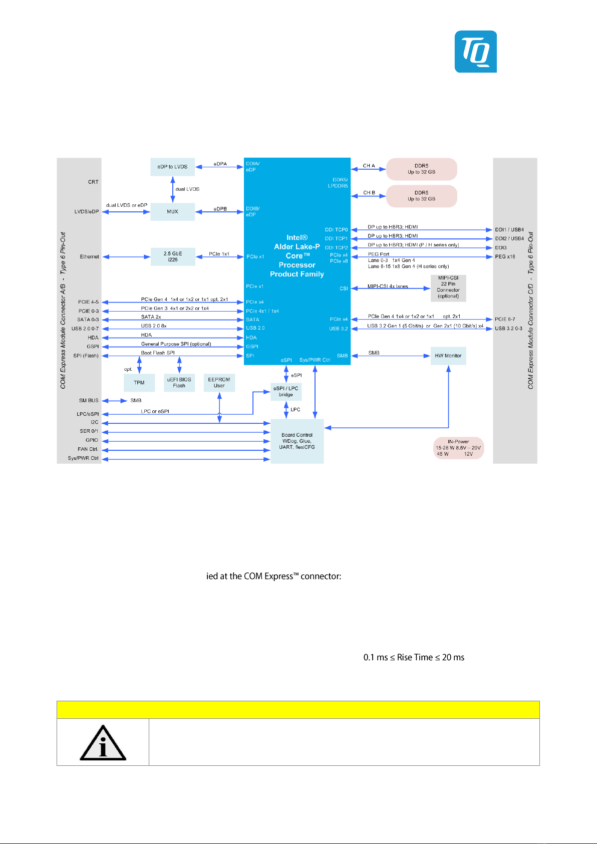
The following figure shows the TQMx120 block diagram.
Figure 1: TQMx120 block diagram
3.2 Electrical Characteristics
3.2.1 Supply Voltage
The TQMx120 supports a wide-range voltage input from 8.5 V to 20 V.
The following supply voltages are specif
Wide input: 8.5 V to 20 V maximum input ripple: ±100 mV (U and P processor series)
Standard input: 11.4 V to 12.6 V maximum input ripple: ±100 mV (H processor series)
VCC_5V_SBY: 4.75 V to 5.25 V maximum input ripple: ±50 mV
VCC_RTC: 2.0 V to 3.3 V maximum input ripple: ±20 mV
The input voltages shall rise from 10 % to 90 % of nominal within 0.1 ms to 20 ms ( ).
The increase of each DC output voltage has to be smooth and continuous from 10 % to 90 % of its final set point within the
regulation range.
Note: Power source
For single supply operations, the 5 V Standby voltage is not required.
VCC_5V_SBY can be left unconnected.

User's Manual l TQMx120 UM 0100 l © 2023, TQ-Systems GmbH Page 14
3.2.2 Power Consumption
The power consumption values below show the TQMx120 voltage and power specifications.
The values were measured with two power supplies; one for the TQMx120 and the other one for the MB-COME6-4
carrier board.
The power consumption of each TQMx120 version was measured running Windows®10, 64-bit and a dual DDR5 SO-DIMM
configuration (2 × 16 Gbyte). All measurements were done at a temperature of +25 °C and an input voltage of +12 V.
The power consumption of the TQMx120 depends on the application, the mode of operation and the operating system.
The power consumption was measured under the following test modes:
•Suspend mode:
The system is in S5/S4 state, Ethernet port is disconnected.
•Windows®10, 64-bit, idle state:
Desktop idle state, Ethernet port is disconnected.
•Windows®10, 64-bit, maximum workload (cTDP down mode enabled):
These values show the maximum cTDP down power consumption using the Intel®stress test tool to stress the
processor and graphic engine. Ethernet port is connected (1000Base-T Speed).
•Windows®10, 64-bit, maximum workload (nominal configuration):
These values show the maximum worst case power consumption using the Intel®stress test tool to stress the processor
and graphic engine. Ethernet port is connected (1000Base-T Speed).
•Windows®10, 64-bit, maximum workload (turbo mode first 28 seconds)
These values show the maximum worst case power consumption using the Intel®stress test tool to stress the processor
and graphic engine. This value was measured only for a short time (28 s) when the processor is in the turbo mode. This
value should be used for designing the power supply for the TQMx120. Ethernet port is connected
(1000Base-T Speed).
User's Manual l TQMx120 UM 0100 l © 2023, TQ-Systems GmbH Page 15
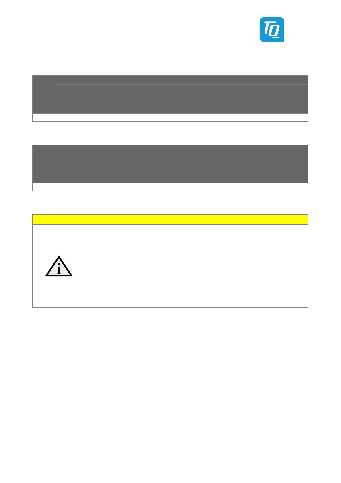
The following table shows the TQMx120 power consumption with different CPUs.
Table 5: TQMx120 Power Consumption Turbo Mode ON
CPU
Mode
Standby 5 V
Input 12 V
Suspend
Win10, 64-bit
idle
Win10, 64-bit
cTDP down
max. load
Win10, 64-bit
nominal
max. load
Win10, 64-bit
Max load
(Turbo mode)
TBD
Table 6: TQMx120 Power Consumption Turbo Mode OFF
CPU
Mode
Standby 5 V
Input 12 V
Suspend
Win10, 64-bit
idle
Win10, 64-bit
cTDP down
max. load
Win10, 64-bit
nominal
max. load
Win10, 64-bit
Max load
(Turbo mode)
TBD
Note: Power requirement
The power supplies on the carrier board for the TQMx120 have to be designed with enough reserve.
The carrier board should be able to provide at least twice the maximum TQMx120 workload power.
The TQMx120 supports several low-power states. The carrier board power supply has to be stable,
even with no load.
Carrier power supply example:
Processor i7-12800HE max. load Turbo ON Power Consumption = 130 W: carrier power design 200 W
Processor i7-12800HE max. load Turbo OFF Power Consumption = 55 W: carrier power design 110 W
Processor i7-1270PE max. load Turbo ON Power Consumption = 90 W: carrier power design 150 W
Processor i7-1270PE max. load Turbo OFF Power Consumption = 35 W: carrier power design 70 W
Processor i7-1265UE max. load Turbo ON Power Consumption = 80 W: carrier power design 120 W
Processor i7-1265UE max. load Turbo OFF Power Consumption = 29 W: carrier power design 60 W
User's Manual l TQMx120 UM 0100 l © 2023, TQ-Systems GmbH Page 16
3.2.3 Real Time Clock Power Consumption
The RTC (VCC_RTC) current consumption is shown below.
The values were measured at +25 °C under battery operating conditions.
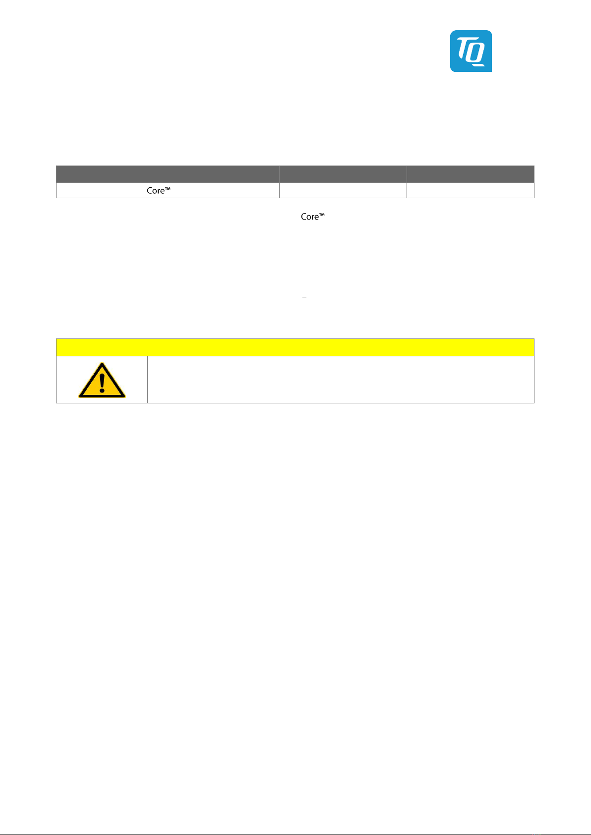
Table 7: RTC Current Consumption
Mode
Voltage
Current
12th Generation Intel®series integrated RTC
3.0 V
3 µA
The current consumption of the RTC in the 12th Generation Intel®series Product Family Datasheet is specified with 6 µA in
average, but the measured values on several TQMx120 are lower.
3.3 Environmental Conditions
•Operating Standard temperature: 0 °C to +60 °C
•Operating Extended temperature: 0 °C to +75 °C
•Storage temperature: 40 °C to +85 °C
•Relative humidity (operating): 10 % to 90 % (non-condensing)
•Relative humidity (storage): 5 % to 95 % (non-condensing)
Attention: Maximum operating temperature
Do not operate the TQMx120 without properly attached heat spreader and heat sink.
The heat spreader is not a sufficient heat sink.

User's Manual l TQMx120 UM 0100 l © 2023, TQ-Systems GmbH Page 17
3.4 System Components
3.4.1 Processor
The TQMx120 supports the 12th Generation Intel®processor series (Alder Lake-P).
The following list illustrates some key features of the 12th Generation Intel®U, P, H processor series:
•First Intel® hybrid processor design combines Performance-cores with Efficient cores, together up to 14 cores
•10nm SuperFin technology
•DDR5 up to 4800 MT/s
•Intel® Hyper-Threading Technology (Intel® HT Technology)
•Intel® Advanced Vector Extensions 2 (Intel® AVX2)
•Intel® AVX2 Vector Neural Network Instructions (Intel® AVX2 VNNI)
•Intel® 64 Architecture
•Intel® Turbo Boost Max Technology 3.0
•Intel® Configurable Thermal Design Power (Intel® cTDP up and down)
•Intel® Enhanced Intel® SpeedStep® technology
•12th generation Intel® UHD Graphics / Iris® XeGraphics with up to 96 Execution Units (EUs)
•High Definition Content Protection (HDCP) 2.3
•Up to four independent displays
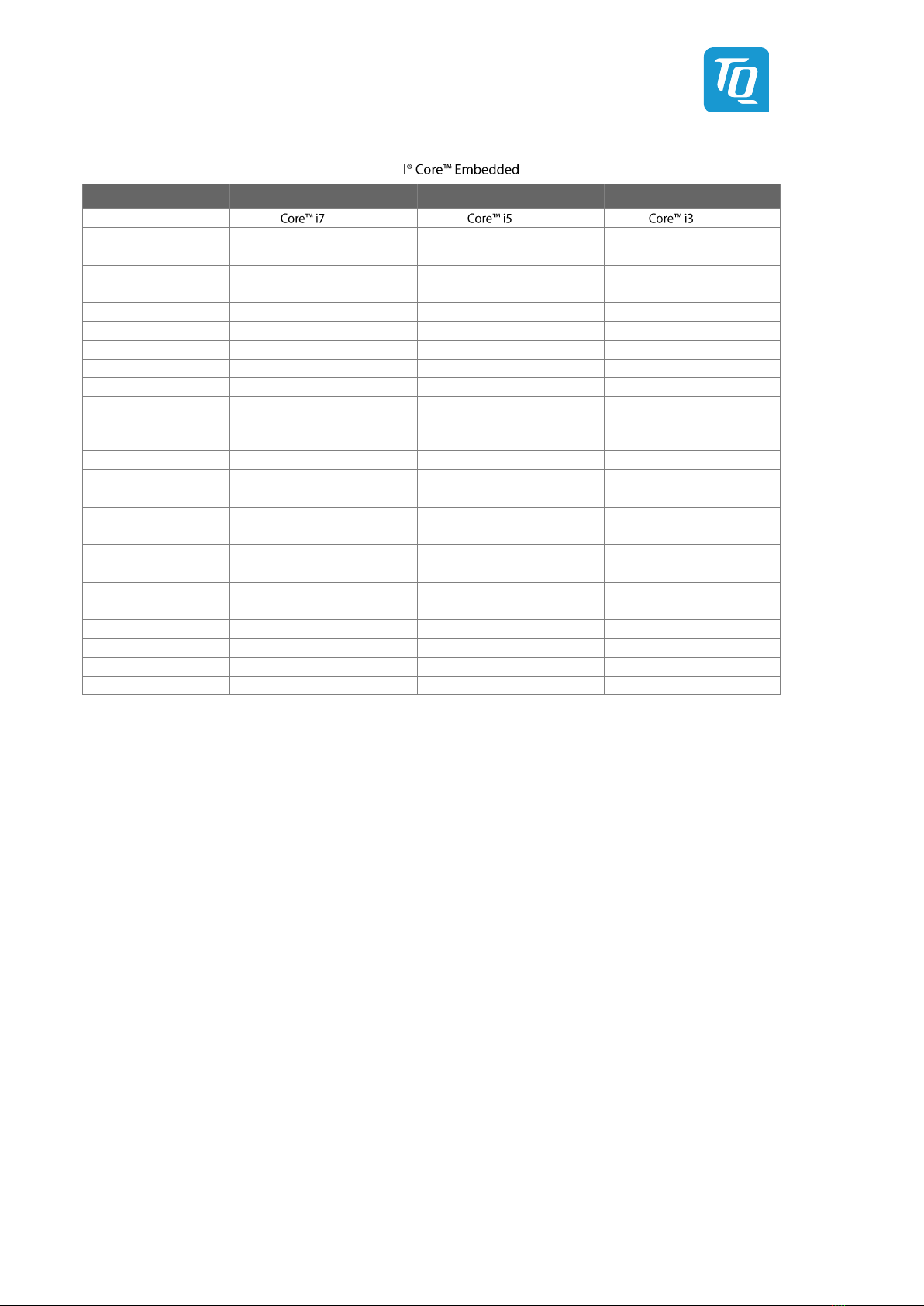
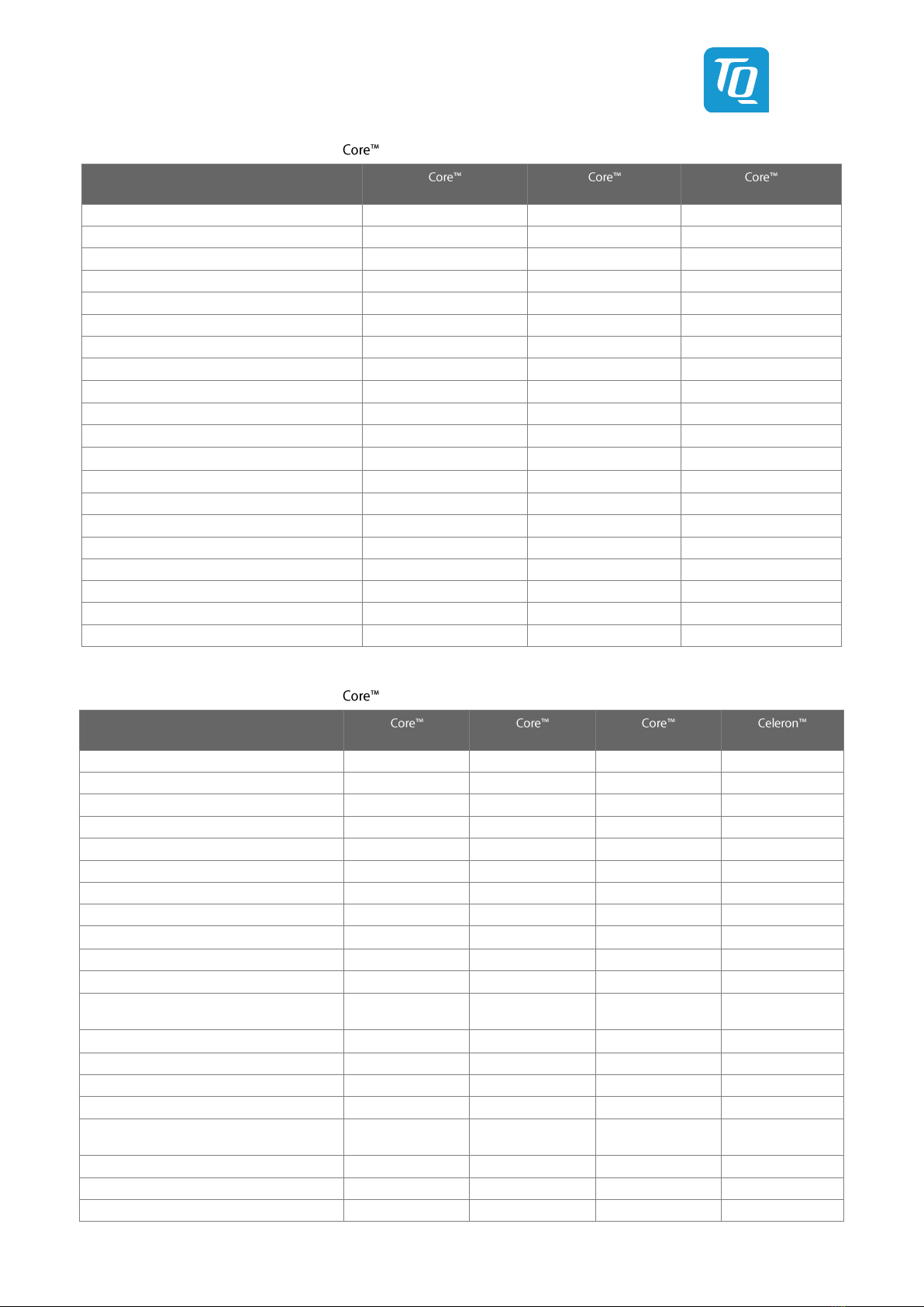
Table 8: 12th Generation Intel®i7, i5, i3 Embedded H-Series
Mode
i7-12800HE
i5-12600HE
i3-12300HE
Processor Cores
6P + 8E
4P + 8E
4P + 4E
Cache
24 Mbyte
18 Mbyte
12 Mbyte
P-Core Base frequency
2.4 GHz
2.5 GHz
1.9 GHz
P-Core Base frequency (cTDP down)
1.6 GHz
1.7 GHz
1.1 GHz
P-Core Max. Turbo frequency
4.6 GHz
4.5 GHz
4.3 GHz
E-Core Base frequency
1.8 GHz
1.8 GHz
1.5 GHz
P-Core Max. Turbo frequency
3.5 GHz
3.3 GHz
3.3 GHz
Tjunction
0 °C to +100 °C
0 °C to +100 °C
0 °C to +100 °C
Memory speed DDR5
4800 MT/s
4800 MT/s
4800 MT/s
Max. memory
64 Gbyte
64 Gbyte
64 Gbyte
Graphics
Intel® Iris® Xe Graphics
Intel® Iris® Xe Graphics
Intel® UHD Graphics
Graphics Execution Units
96
80
48
Graphics Turbo frequency
1.35 GHz
1.3 GHz
1.15 GHz
Thermal Design Power (TDP nominal)
45 W
45 W
45 W
Configurable Thermal Design Power (cTDP down)
35 W
35 W
35 W
Processor Power Limit 2 (PL2)
115 W
115 W
90 W
Intel®Hyper-Threading Technology
Yes
Yes
Yes
Chipset
600 Series
600 Series
600 Series
User's Manual l TQMx120 UM 0100 l © 2023, TQ-Systems GmbH Page 18
Table 9: 12th Generation Intel®i7, i5, i3 Embedded P-Series
Mode
i7-1270PE
i5-1250PE
i3-1220PE
Processor Cores
4P + 8E
4P + 8E
4P + 4E
Cache
18 Mbyte
12 Mbyte
12 Mbyte
P-Core Base frequency
1.8 GHz
1.7 GHz
1.5 GHz
P-Core Base frequency (cTDP up)
1.9 GHz
1.8 GHz
1.7 GHz
P-Core Base frequency (cTDP down)
1.2 GHz
1.1 GHz
1.0 GHz
P-Core Max. Turbo frequency
4.5 GHz
4.4 GHz
4.2 GHz
E-Core Base frequency
1.2 GHz
1.2 GHz
1.1 GHz
P-Core Max. Turbo frequency
3.3 GHz
3.2 GHz
3.1 GHz
Tjunction
0 °C to +100 °C
0 °C to +100 °C
0 °C to +100 °C
Memory speed DDR5
4800 MT/s
4800 MT/s
4800 MT/s
Max. memory
64 Gbyte
64 Gbyte
64 Gbyte
Graphics
Intel® Iris® Xe Graphics
Intel® Iris® Xe Graphics
Intel® UHD Graphics
Graphics Execution Units
96
80
48
Graphics Turbo frequency
1.35 GHz
1.3 GHz
1.25 GHz
Thermal Design Power (TDP nominal)
28 W
28 W
28 W
Configurable Thermal Design Power (cTDP up)
35 W
35 W
35 W
Configurable Thermal Design Power (cTDP down)
20 W
20 W
20 W
Processor Power Limit 2 (PL2)
64 W
64 W
64 W
Intel®Hyper-Threading Technology
Yes
Yes
Yes
Chipset
600 Series
600 Series
600 Series
Table 10: 12th Generation Intel®i7, i5, i3 Embedded U-Series
Mode
i7-1265UE
i5-1245UE
i3-1215UE
7305E
Processor Cores
2P + 8E
2P + 8E
2P + 4E
1P + 4E
Cache
12 Mbyte
12 Mbyte
10 Mbyte
8 Mbyte
P-Core Base frequency
1.7 GHz
1.5 GHz
1.2 GHz
1.0 GHz
P-Core Base frequency (cTDP up)
2.6 GHz
2.5 GHz
2.5 GHz
--
P-Core Base frequency (cTDP down)
1.1 GHz
1.1 GHz
0.8 GHz
0.8 GHz
P-Core Max. Turbo frequency
4.7 GHz
4.4 GHz
4.4 GHz
--
E-Core Base frequency
1.2 GHz
1.1 GHz
0.9 GHz
0.9 GHz
P-Core Max. Turbo frequency
3.5 GHz
3.3 GHz
3.3 GHz
--
Tjunction
0 °C to +100 °C
0 °C to +100 °C
0 °C to +100 °C
0 °C to +100 °C
Memory speed DDR5
4800 MT/s
4800 MT/s
4800 MT/s
4800 MT/s
Max. memory
64 Gbyte
64 Gbyte
64 Gbyte
64 Gbyte
Graphics
Intel® Iris® Xe
Graphics
Intel® Iris® Xe
Graphics
Intel® UHD
Graphics
Intel® UHD
Graphics
Graphics Execution Units
96
80
64
48
Graphics Turbo frequency
1.25 GHz
1.2 GHz
1.1 GHz
1.1 GHz
Thermal Design Power (TDP nominal)
15 W
15 W
15 W
15 W
Configurable Thermal Design Power (cTDP up)
28 W
28 W
28 W
--
Configurable Thermal Design Power (cTDP
down)
12 W
12 W
12 W
12 W
Processor Power Limit 2 (PL2)
55 W
55 W
55 W
55 W
Intel®Hyper-Threading Technology
Yes
Yes
Yes
Yes
Chipset
600 Series
600 Series
600 Series
600 Series
User's Manual l TQMx120 UM 0100 l © 2023, TQ-Systems GmbH Page 19
3.4.1.1 Intel®Turbo Boost Technology
Intel®Turbo Boost Technology accelerates processor and graphics performance for peak loads, automatically allowing processor
cores to run faster than the rated operating frequency if they are operating below power, current, and temperature specification
limits. Whether the processor enters into Intel®Turbo Boost Technology and the amount of time the processor spends in that
state depends on the workload and operating environment.
The Intel® Turbo Boost Technology allows the processor to operate at a power level that is higher than its Thermal Design Power
(TDP) configuration for short durations to maximize performance.
The Intel®
Only the Intel® i3 processors support Intel® Turbo Boost Technology.
3.4.1.2 Intel®Configurable Thermal Design Power
The Intel®Configurable Thermal Design Power (cTDP) feature allows adjustment of the processor power consumption.
The cTDP consists of three modes:
1. The cTDP nominal mode specifies the processor rated frequency and maximum power consumption.
2. The cTDP down mode specifies a lower maximum processor power consumption and lower guaranteed frequency
versus the nominal mode. This mode can be selected for ultra low-power applications, e.g. systems with reduced
cooling solutions.
3. The cTDP up mode specifies a higher maximum processor power consumption and a higher guaranteed frequency
versus the nominal mode. This mode can be selected for high performance applications with optimized cooling
solutions.
3.4.2 Graphics
The 12th Generation Intel®series includes an integrated Intel®HD graphics accelerator.
It provides excellent 2D / 3D graphics performance with support of up to four simultaneous displays.
The following list illustrates some key features of the 12th Generation Intel®processor:
•Intel® Iris® Xe Graphics with up to 96 Execution Units
•Hardware accelerated video decoding/encoding for AVC/VC-1/MPEG2/HEVC/VP8/JPEG
•Direct3D* 2015, Direct3D 12, Direct3D 11.2, Direct3D 11.1, Direct3D 9, Direct3D 10, Direct2D Video API support
•OpenGL 4.5
•Open CL 2.1, Open CL 2.0, Open CL 1.2
•Single 8K60Hz (HBR3) panel support
The TQMx120 supports three external Digital Display Interfaces (DDI1, DDI2 and DDI3) and one internal display, either dual
channel LVDS or eDP , depending on TQMx120 and carrier configuration.
The 12th Generation series supports up to four displays (P and H series) at the same time.
Table 11: Maximum Resolution Display Configuration
Display
Maximum Display Resolution
LVDS
1920 × 1200 @ 60 Hz
eDP 1.4b
4096 × 2304 @ 60 Hz
DP 1.4a
7680 × 4320 @ 60 Hz
HDMI 2.0b
4096 × 2160 @ 60 Hz
3.4.3 Chipset
The 12th Generation Intel®processor series includes the embedded 600 series platform controller hub (PCH).
This manual suits for next models
13
Table of contents
Other TQ Industrial PC manuals

Popular Industrial PC manuals by other brands

FabiaTech
FabiaTech FX5637 Series User quick reference guide

Siemens
Siemens SIMATIC IPC BX-32A operating instructions

Advantech
Advantech TPC-xx51T-x3BE Series user manual

Advantech
Advantech UNO-3483G Series user manual

Rockwell Automation
Rockwell Automation Allen-Bradley 6155F-NPXP user manual

Aaeon
Aaeon PFM-550S user manual


