Tracmaster ARTIO BC65 User guide

ORIGINAL INSTRUCTION MANUAL
Before commissioning the machine, read operang instrucons
and observe warning and safety instrucons.
Manufactured by Tracmaster Ltd
BC65 Lawn Scarier

ARTIO BC65 Lawn Scarier
BC65 Lawn Scarier
Manufacturer Details
Tracmaster Ltd
Units 6-7 Winterpick Business Park
Hurstpierpoint Road
Wineham
Heneld
BN5 9BJ
UNITED KINGDOM
Tel: +44 (0)1444 247689
www.tracmaster.co.uk
info@tracmaster.co.uk
Machine Details
Model: ARTIO BC65 Lawn Scarier
Serial No: A 5 1 - 11111
Purchase Date: D D -M M -Y Y Y Y
Supplier:

ARTIO BC65 Lawn Scarier
BC65 Lawn Scarier Page 1
Table of Contents
1.0 Introducon .............................................................................................................................2
1.1 Welcome ................................................................................................................................2
1.2 About This Manual ................................................................................................................2
2.0 What the Machine is Designed For............................................................................................3
2.1 Applicaons ...........................................................................................................................3
3.0 Specicaons............................................................................................................................4
4.0 Unpacking and Assembly ..........................................................................................................5
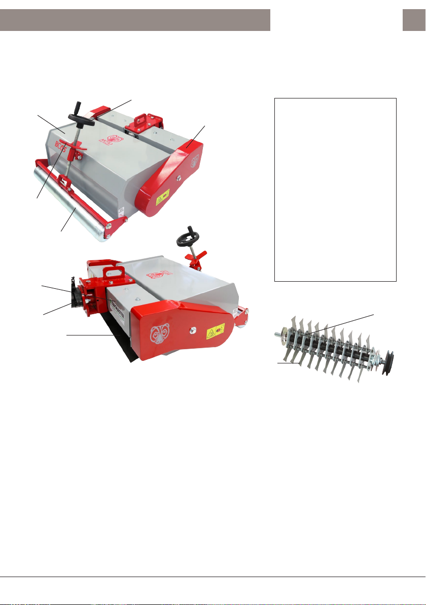
4.1 Major Components Diagram .................................................................................................5
4.2 Unpacking Instrucons ..........................................................................................................5
5.0 Preparing for Use .....................................................................................................................6
5.1 Aaching to the Power Unit ..................................................................................................6
6.0 Operang the Lawn Scarier.....................................................................................................7
6.1 Transporng...........................................................................................................................7
6.2 Working the BC65 Lawn Scarier ..........................................................................................7
6.3 Stopping the BC65 Lawn Scarier ..........................................................................................8
6.4 Adjusng the working height of the Scarier for dierent size wheels .................................8
7.0 Maintenance ............................................................................................................................9
7.1 Regular Maintenance Checks ................................................................................................9
7.2 Belt Maintenance ..................................................................................................................9
7.3 Belt Tensioning ......................................................................................................................9
7.4 Gearbox Maintenance .........................................................................................................10
7.5 Rotor Bearings Maintenance ...............................................................................................10
7.6 Drive Sha Bearing Maintenance ........................................................................................10
7.7 General Rotor Maintenance ................................................................................................10
7.8 Rotang the Blades ..............................................................................................................10
7.9 Changing the Blades ............................................................................................................11
7.10 Replacing the Rods ..............................................................................................................11
7.11 Storage.................................................................................................................................11
7.12 Handling ..............................................................................................................................12
8.0 Warranty ................................................................................................................................13
8.1 Condions of Warranty .......................................................................................................13
8.2 Warranty Registraon ..........................................................................................................14
9.0 Spare Parts .............................................................................................................................15
9.1 Parts Diagrams .....................................................................................................................15
10.0 Service Record ........................................................................................................................16
11.0 EC Declaraon of Conformity..................................................................................................17

ARTIO BC65 Lawn Scarier
Page 2 BC65 Lawn Scarier
1.0 Introducon
1.1 Welcome
Welcome to Tracmaster and thank you for choosing ARTIO.
We are condent that you will be more than happy with your machine.
Your machine is covered by a comprehensive warranty. However, the lifespan of
your ARTIO machine depends on a number of factors. It is important that you read
this manual carefully and follow the instrucons regarding operaon, maintenance,
and care.
1.2 About This Manual
It is crucial that you read this manual carefully and understand it. Reading and
understanding this manual should prevent you from operang the BC65 incorrectly
and so extend the life of the machine.
This manual also contains important safety informaon about your machine. You
must observe all safety instrucons at all mes. ARTIO machines are oen updated
and improved so models may vary due to dierences in specicaons.
Any illustraons, descripons, specicaons, and technical data in this manual is
correct at the me of prinng.
For any quesons relang to this manual please contact us.
During oce hours (UK) we can be contacted on:
Phone: +44 (0)1444 247689
Email: info@tracmaster.co.uk
Website: www.tracmaster.co.uk
IMPORTANT!
READ THIS MANUAL
CAREFULLY
!

ARTIO BC65 Lawn Scarier
BC65 Lawn Scarier Page 3
2.0 What the Machine is Designed For
2.1 Applicaons
The ARTIO BC65 Lawn Scarier has been designed by Tracmaster for removing the
dead thatch and moss from lawns and other grassed areas.
The benet of scarifying a lawn is that it allows air, water and nutrients to reach the
roots of the grass whilst removing unwanted dead and foreign material.
The blades of the BC65 Scarier are designed to pass through the grass ONLY - they
are NOT designed to make contact with solid ground at any point during operaon.
The machine will be damaged if blades connuously come into contact with solid
ground.
DO NOT use the ARTIO BC65 Scarier for cung grass or sling the ground.
Both operaons will result in damage to the machine.
Operang the machine on non-grass surfaces such as concrete or tarmac will cause
damage to the BC65 Scarier.
DO NOT scarify your lawn if there is a likelihood of high temperatures or drought.
Irrigate the lawn if necessary to ensure that the grass benets from its treatment.

ARTIO BC65 Lawn Scarier
Page 4 BC65 Lawn Scarier
3.0 Specicaons
MACHINE
Model BC65
Working Width 59cm
Cartridge Types Free Swinging Fixed Spring Rake
Number of Blades 48 24 42
Direcon of Rotor Rotor rotates in the same direcon as travel
Height Adjustment From 0mm above ground to 20mm
Max Gradient for Operaon on Slope 20 degrees
Weight 65kg
Dimensions (l x w x h) 82 x 77 x 50cm

ARTIO BC65 Lawn Scarier
BC65 Lawn Scarier Page 5
4.0 Unpacking and Assembly
4.1 Major Components Diagram
①Chassis
② Roller
③ Locking Knob
④ Height Adjuster Handle
⑤ Cover
⑥ Gearbox Frame
⑦ Rear Flap
⑧ Coupler
⑨ Rotor Assembly
⑩ Blade
4.2 Unpacking Instrucons
The BC65 Lawn Scarier is usually delivered on a pallet and covered with pallet
wrap.
Carefully remove any outer packaging.
Locate and remove any cable es or straps that secure the Scarier to the pallet.
Push the machine forward safely and gently o the pallet.
Dispose of any packing material, please reuse or recycle where possible.
⑧
⑦
⑤
②
④
⑥
③
①
⑩
⑨

ARTIO BC65 Lawn Scarier
Page 6 BC65 Lawn Scarier
5.0 Preparing for Use
5.1 Aaching to the Power Unit
The ARTIO BC65 Lawn Scarier will be delivered already assembled, lubricated and
ready for work. It will need to be aached to the power unit. This is achieved as
follows.
BCS 738 - BCS 740 - BCS 630 - BCS 630WS
To aach the Lawn Scarier to the BCS 738 and 740 power units, couple the
implement to the machine PTO and make sure the nuts are ghtened securely.
If the Implement Quick Coupling Assembly is being simply move the locking pin
lever to raise the pin, then slide the male coupler (ed to the Scarier) into the
female coupler (ed to the power unit) unl the sloed hole lines up with the
locking pin. Once the couplers are lined up in the correct posion, release the
locking lever to secure the two couplers together (Fig 1).
BCS 750 - BCS 660HY
The Lawn Scarier is mounted directly to the machine coupler (Fig 2,A) by aaching
the coupler (Fig 3,C) that is xed to the implement.
To t and remove the Lawn Scarier simply rotate the knob (Fig 3,R). The device
is locked by turning the knob clockwise and unlocked by turning the knob an-
clockwise. It is important that nuts (Fig 3,D) are well ghtened.

ARTIO BC65 Lawn Scarier
BC65 Lawn Scarier Page 7
6.0 Operang the Lawn Scarier
IMPORTANT: Always read all separate instrucon manuals supplied with the
power unit before use, to ensure you are familiar with the machine’s controls.
6.1 Transporng
To transport the BC65 Lawn Scarier, wind the height adjuster to its highest posion
where the blades are the furthest from the ground.
NB: ENSURE THE PTO LEVER IS NOT ENGAGED ON YOUR POWER UNIT. DO NOT
ENGAGE THE PTO LEVER DURING TRANSPORTATION.
Select a suitable speed gear and proceed with cauon.
6.2 Working the BC65 Lawn Scarier
Clear the grass area of all objects that may be present on the ground. These may
cause damage to you and the machine if you run over them whilst the scarier is
working.
THE SCARIFIER WORKS MOST EFFICIENTLY ON SHORT GRASS. DO NOT USE THE
SCARIFIER IN LONG GRASS.
Ensure the working area is clear of people.
Ensure that during the operaon of the scarier people cannot enter the working
area.
Posion the machine on a at working area.
Ensure that the machine is switched o and the engine is not running.
At the front of the scarier use the Height Adjuster Knob to change the height of the
blades to your required working height.
A STICKER LOCATED ON THE SIDE OF THE MACHINE INDICATES THE HEIGHT OF THE
BLADES.
AT FIRST SET THE WORKING HEIGHT OF THE BLADES SIGNIFICANTLY ABOVE THE
GROUND LEVEL.
LOCK THE REQUIRED WORKING HEIGHT USING THE LOCKING KNOB.
Follow the instrucons for your two-wheel tractor to engage the wheel drive and
pto drive to the scarier aachment.
Assess the performance of the scarier over a 2-3m length of grass.
To lower the height of the blades, stop the power unit and turn the engine o to
ensure there is no drive to the wheels or power take o.
Use the height adjuster knob to lower the blades as indicated by the height scker
on the side of the machine.
!

ARTIO BC65 Lawn Scarier
Page 8 BC65 Lawn Scarier
6.3 Stopping the BC65 Lawn Scarier
The BC65 Lawn Scarier is controlled via your two-wheel tractor power unit. To stop
the machine, follow the standard operang procedures to stop the wheel drive and
power take o drive as instructed in your two-wheel tractor manual.
6.4 Adjusng the working height of the Scarier for dierent size wheels
The working height of the BC65 Lawn Scarier can be modied for power units with
dierent size wheels.
The inial set of the BC65 is in the posion suitable for 5x10 agricultural wheels.
NB: WE RECOMMEND THAT THIS IS UNDERTAKEN BY AN EXPERIENCED MECHANIC.
Loosen the tension on the belts by loosening the belt tension bolts.
Remove the side cover guards from the machine.
Loosen but do not remove the two bolts at the boom of the side plates that are
located around the rotor bearings. DO NOT UNDO THE NUTS ON THE ACTUAL
BEARING ITSELF.
Remove the nuts from the two bolts located in the centre of the side plates. Remove
the square coach bolts from the inside of the chassis.
It is now possible to rotate the side plates to a higher posion that suits a power
unit with 6.5x12 agricultural wheels, or to rotate the side plates to a lower posion
for 4x10 agricultural wheels.
Insert the square coach bolts from the inside of the chassis so that they locate the
side plates in their new posion. Fix the locking nuts onto these bolts.
Tighten the nuts and bolts at the boom of the side plates.
Re-aach the belt guard.
Re-tension the belts using the belt tensioning bolts.
See Fig 4 for pictorial representaons.

ARTIO BC65 Lawn Scarier
BC65 Lawn Scarier Page 9
7.0 Maintenance
7.1 Regular Maintenance Checks
Always clean the Lawn Scarier aer use.
Remove any wire, string, plasc neng etc from the rotor shas and bearings.
7.2 Belt Maintenance
Check the condion of the belts aer the rst four hours of work.
To do this remove the right-hand cover guard by unscrewing the central bolt.
Assess the belts for wear and damage and replace if necessary. Both belts should
exhibit and equal amount of tension when compared. If the belts are not equally
tensioned then replace both belts.
Aer checking the belts replace the right cover guard and ghten the bolt.
7.3 Belt Tensioning
The two belts are tensioned using the belt tensioning bolts located under the
gearbox frame (Fig 5).
Remove the gearbox frame covers by
undoing the two bolts holding each
cover onto the gearbox frame.
Lightly loosen the 4 nuts that connect
the gearbox frame to the side plates on
both inside ends of the gearbox frame.
Loosen the locking nut on the belt
tensioning bolts and unwind the locking
nut away from the hexagonal holder.
Using a 19mm ratchet spanner wind the belt tensioning bolts clockwise to tension
the belts.
NB: Ensure that the belt tensioning bolts are set at an equal length so that the
gearbox frame remains square in its posion relave to the chassis. Measure the
distance from the chassis to the edge of the gearbox frame and adjust the belt
tensioning bolts accordingly unl the gearbox frame is parallel to the main chassis.
Once the belts are tensioned and the gearbox frame is square, lock the posion of
the belt tensioning bolts using the locking nut.
Tighten the four bolts that were previously loosened at each end of the gearbox
frame.
Re-aach the gearbox covers on both sides.

ARTIO BC65 Lawn Scarier
Page 10 BC65 Lawn Scarier
7.4 Gearbox Maintenance
The gearbox is lled with 350ml of gear oil. This should be checked every 50 hours
of work.
7.5 Rotor Bearings Maintenance
Both rotor bearings can be greased, although be aware it is possible to over grease
the bearings as well as under grease them.
Check and if necessary grease the bearings every 20 hours.
To access to the rotor bearings, remove the side guard by undoing the single bolt
holding the cover to the machine.
7.6 Drive Sha Bearing Maintenance
The drive sha bearing can be greased, although be aware it is possible to over
grease the bearings.
Check and if necessary grease the bearings every 20 hours.
Removing the right-hand gearbox frame cover provides clear access to the drive
sha bearing.
7.7 General Rotor Maintenance
Check the rotor aer each use to ensure that the blades are clear from wire, rope
and similar material that could damage the blades, rods or springs.
Ensure the rotors are not missing any blades or springs and that the rods that hold
the blades are not showing any signs of wear or damage. If a rod is showing signs of
wear then replace the rods.
Check the rotor sha does not have any material wrapped around it close to the
rotor bearings. Remove any material that could get pushed into the bearings
causing damage.
7.8 Rotang the Blades
The BC65 features a system that
allows you to remove a rod from the
rotor assembly and to rotate and re
insert it so that the unused side of the
blades can be ulised.
To do this, use a set of 13mm
spanners to remove the bolts from
the rod holders connecng a rod
onto the central hexagonal plates.
There are 5 rod holders per rod, each
of which is connected to a hexagonal
mounng plate.

ARTIO BC65 Lawn Scarier
BC65 Lawn Scarier Page 11
Once the rod has been removed, rotate the rod 180o and then re-insert the rod
holders back into the hexagonal plates but this me bolng them into the adjacent
locang slot on the other side of the plate. See Fig 6.
NB: IT IS IMPORTANT THAT ALL 3 RODS ARE ROTATED AT THE SAME TIME TO
ENSURE THAT THE ROTOR REMAINS BALANCED DURING OPERATION.
Ensure that the bolts holding each rod holder onto the mounng plates are ght.
7.9 Changing the Blades
The rotor is made up of three rods with each containing blades or springs, spaces,
spacer springs and rod holders.
Each rod is congured dierently to ensure that the scarier blades cover a wide an
area as possible and to ensure each blade does not hit another during operaon.
The three conguraons are as below (Fig 7).
Each rod can be disassembled.
The rst step is to remove the split
pin used to contain the elements
of the rod. Once this has been
removed it is possible to slide the
components easily o one of the
rod.
Assemble the rods according to
the diagram (Fig 7) using a new
split pin to hold the conguraon
together. Once assembled the rods
can be reinserted into the rotor.
7.10 Replacing the Rods
Unbolt the rod from the rotor assembly by undoing the 5 bolts that connect the rod
holders to the hexagonal plate for the rod you wish to change.
Remove the split pin from the end of the rod and slide the components o the rod.
Using a new rod, t a split pin and washer to one end and slide on the components
required in the same order as they were removed. Use Fig 5 as a guide to help you
t the components in the correct order.
Once the rod has been assembled and secured with a split pin, aach the rod
holders of the rod assembly to the hexagonal mounng plate in the same posion
from which it was removed.
7.11 Storage
Always store BC65 Lawn Scarier in a clean, dry place.

ARTIO BC65 Lawn Scarier
Page 12 BC65 Lawn Scarier
Always clean the machine and dry thoroughly prior to storage and ensure all
lubricaon points have been re-greased.
7.12 Handling
Do not aempt to li the machine alone. At least two people is the minimum
required.
Gloves must be worn when liing the BC65 Lawn Scarier.
When performing maintenance on the BC65 Lawn Scarier, if it is situated on a
work bench, ensure that the machine is rmly held in posion at all mes.

ARTIO BC65 Lawn Scarier
BC65 Lawn Scarier Page 13
8.0 Warranty
8.1 Condions of Warranty
Tracmaster Ltd guarantees all equipment supplied by them against any defect in
The Warranty applies to any part of the machine, except the engine, which presents
manufacturing or assembly defects in the opinion of Tracmaster Ltd.
The Warranty covers the original purchaser of the machine from the date of sale for
the warranty period. The Warranty is non-transferable.
The warranty period begins the day the machine is delivered to the customer and is
valid for the following periods:
• For domesc or private use: 3 years
• For commercial and hire use: 2 years
Tracmaster Ltd will replace or repair, at their discreon, free of charge, any such
defecve material providing the machine is returned to their workshops or an
Authorised Tracmaster Dealer (contact us or see www.tracmaster.co.uk).
Should the owner of the machine wish to install the parts themselves then the
labour involved will be at their cost and will not be reimbursed. Expenses arising
from any subsequent failure of any part due to incorrect assembly by the owner of
the machine shall be borne by the owner of the machine.
To validate warranty the Warranty Registraon Card must be completed and
returned, or complete the form online at www.tracmaster.co.uk/pages/warranty-
registraon-form.
The Warranty does not cover any transport costs, or direct or indirect losses
owing to loss of use of the machine as a consequence of manufacturing defects or
mechanical failure.
No Warranty shall be acknowledged in the following instances:
• The failure is caused by non-compliance of Tracmaster’s direcons for the
correct use and operaon of the machine.
• Seals and sengs have been tampered with.
• Repair or modicaon has not authorised by Tracmaster Ltd.
• Roune maintenance, as advised in this manual, has not been undertaken.
• Incorrect fuels or lubricants have been used.
• Wear to consumable items such as blades, nes, belts, cables, tyres etc.
• Normal wear and tear.
• The failure is due to abuse / misuse / neglect.

ARTIO BC65 Lawn Scarier
Page 14 BC65 Lawn Scarier
For any issues relang to the engine please contact an authorised service centre
for the engine. The engines are warranted according to the pracces set by their
respecve manufacturers and distributors.
If an issue develops with the machine, within the warranty period, the problem
must be vered by Tracmaster or an Authorised Tracmaster Dealer before any
repair is undertaken.
Any other express or implied warranty is cancelled and substuted by this Warranty,
whose clauses can be modied in wring only.
This Warranty provides specic legal rights and is in addion to any statutory rights.
Your statutory rights are not aected by this Warranty.
For any queries relang to this Warranty Informaon please contact our Technical
Department at Tracmaster.
8.2 Warranty Registraon
To validate your warranty please complete and return the enclosed FREEPOST card.
Alternavely, complete the online registraon form at www.tracmaster.co.uk.

ARTIO BC65 Lawn Scarier
BC65 Lawn Scarier Page 15
9.0 Spare Parts
9.1 Parts Diagrams
The spare parts diagrams and part numbers for the ARTIO BC65 Lawn Scarier can
be found on our website or by contacng our spare parts department.
Spare parts can be ordered via the following methods:
Phone: +44(0) 1444 247689 (opon 1)
Website: www.tracmaster.co.uk
Email: spares@tracmaster.co.uk
Or via your local Authorised Dealer.

ARTIO BC65 Lawn Scarier
Page 16 BC65 Lawn Scarier
10.0 Service Record
To ensure your machine is kept in peak condion we recommend that your ARTIO BC65
Lawn Scarier is serviced at regular intervals.
Contact Tracmaster on 01444 247689 to nd out who your local Authorised Tracmaster
Dealer is, or check our Dealer Locator online at www.tracmaster.co.uk.
Company: Company:
Date: Date:
Company
Stamp:
(or address
& authorised
signature)
Company
Stamp:
(or address
& authorised
signature)
Company: Company:
Date: Date:
Company
Stamp:
(or address
& authorised
signature)
Company
Stamp:
(or address
& authorised
signature)
Company: Company:
Date: Date:
Company
Stamp:
(or address
& authorised
signature)
Company
Stamp:
(or address
& authorised
signature)
1 2
3 4
5 6

ARTIO BC65 Lawn Scarier
BC65 Lawn Scarier Page 17
11.0 EC Declaraon of Conformity
Tracmaster Ltd declares that the machinery spulated below complies with all the relevant
provisions of:
Machinery Direcve 2006/42/EC
EMC Direcve 2004/108/EC
and the Naonal Laws and Regulaons adopng these direcves and other relevant direcve.
Manufacturer: Tracmaster Ltd
Units 6-7 Winterpick Business Park
Hurstpierpoint Road
Wineham
Heneld
BN5 9BJ
UNITED KINGDOM
Machine Descripon: Lawn Scarier
Type: ARTIO BC65
Harmonised Standards applied (including parts of):
EN 294:1992 Safety of machinery: Safety distance to prevent danger zones
being reached by the upper limbs.
EN 954-1:1996 Safety of machinery: Safety related parts of control systems. Part
1 – general principles for design.
EN 20643:2008+A1:2012 Hand arm vibraon: Laboratory measurement of vibraon at the
grip surface of hand guided machinery – general.
EN 12100-1:2003 &
EN12100-2:2003
Safety of machinery: Basic concepts, general principles for design
parts 1 & 2.
EN 13684:2004+A2:2009 Garden equipment. Pedestrian controlled lawn aerators and
scariers.
ISO 11684:1995
Tractors, machinery for agriculture and forestry, powered lawn
and garden equipment: Safety signs and hazard pictorials – general
principles.
Responsible Person: Jody Symons
Posion in Company: Technical Director
Address: Tracmaster Ltd, Units 6-7 Winterpick Business Park, Hurstpierpoint Road,
Wineham, Heneld, BN5 9BJ
Date: March 2020
Signature: ........................................................................................

Tracmaster Ltd
Units 6-7 Winterpick Business Park | Hurstpierpoint Road | Wineham | Heneld | BN5 9BJ | UK
Tel: +44 (0)1444 247689 | www.tracmaster.co.uk | [email protected]
ARTIO BC65 Lawn Scarier
Original Instrucon Manual
© 2021 Tracmaster Ltd
Other manuals for ARTIO BC65
1
This manual suits for next models
1
Table of contents
Other Tracmaster Lawn And Garden Equipment manuals

Tracmaster
Tracmaster BCS630 Instruction Manual

Tracmaster
Tracmaster Camon LS52 User guide

Tracmaster
Tracmaster BCS615L Instruction Manual

Tracmaster
Tracmaster Camon LS14 User guide

Tracmaster
Tracmaster Camon C6 Instruction Manual

Tracmaster
Tracmaster CAMON LS42 User manual

Tracmaster
Tracmaster CAMON TC07 Operating manual

Tracmaster
Tracmaster Camon LS14 User manual

Tracmaster
Tracmaster CAMON LS17 Instruction Manual

Tracmaster
Tracmaster Camon LS42B1 User guide