TrailFX FHDB006TI User manual

www
.
T
r
a
il
F
X
.
c
o
m
Page 1of 7 Rev 121218
READ INSTRUCTIONS CAREFULLY BEFORE STARTING INSTALLATION.
REMOVE CONTENTS FROM BOX. VERIFY ALL PARTS ARE PRESENT.
DO NOT OVER TORQUE.STANDARD OPERATING LOAD FOR TIGHTEN
BODY MOUNT NUTS & BOLTS VARIES FROM 45 TO 65 FOOT POUND.
ASSISTANCE IS HIGHLY RECOMMENDED
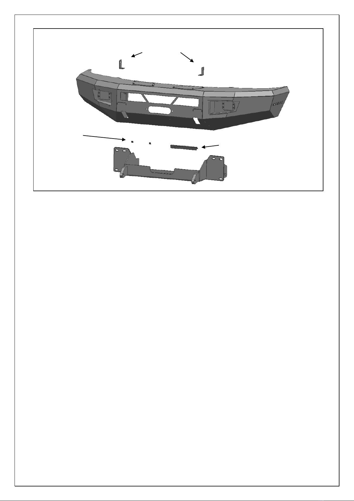
PARTS LIST:
Qty Part Description Qty Part Description
1
HD1 Front Bumper Assembly
6
10mm Lock Washers
1
Winch Tray Bracket Assembly
6
10mm Hex Nuts
2
Plastic Plugs for license plate mount
2
8-1.25mm x 25mm Hex Bolts
1
License Plate Bracket
2
8-1.25mm x 16mm Hex Bolts
1
Offset Left LED Bracket
6
8mm x 24mm x 2mm Flat Washers
1
Offset Right LED Bracket
4
8mm Lock Washers
4
12-1.75mm x 170mm Hex Bolts
2
8mm Hex Nuts
8
12-1.75mm x 50mm Hex Bolts
2
6mm x 20mm Button Head Screw
24
12mm x 32mm x 3mm Flat Washers
4
6mm x 18mm x 1.6mm Flat Washers
12
12mm Lock Washers
2
6mm Nylon Lock Nut
12
12mm Hex Nuts
1
4mm Wrench(6mm)
6
10mm x 34mm x 3mm Flat Washers
Front HD Bumper
Part No.
FHDB006TI
Fits: 2017-Current Ford F250/350 Superduty
POLISHED STAINLESS STEEL – LIMITED LIFETIME
POWDER COATED BLACK – 3 YEARS
1 866 638 4870
60-180 min
DRILLING NOT
REQUIRED
CUTTING NOT
REQUIRED
www
.
T
r
a
il
F
X
.
c
o
m
Page 2of 7 Rev 121218
PROCEDURE:
REMOVE CONTENTS FROM BOX. VERIFY ALL PARTS ARE PRESENT. READ INSTRUCTIONS
CAREFULLY BEFORE STARTING INSTALLATION. BUMPER IS HEAVY, ASSISTANCE IS HIGHLY
RECOMMENDED TO AVOID POSSIBLE INJURY OR DAMAGE TO THE VEHICLE.
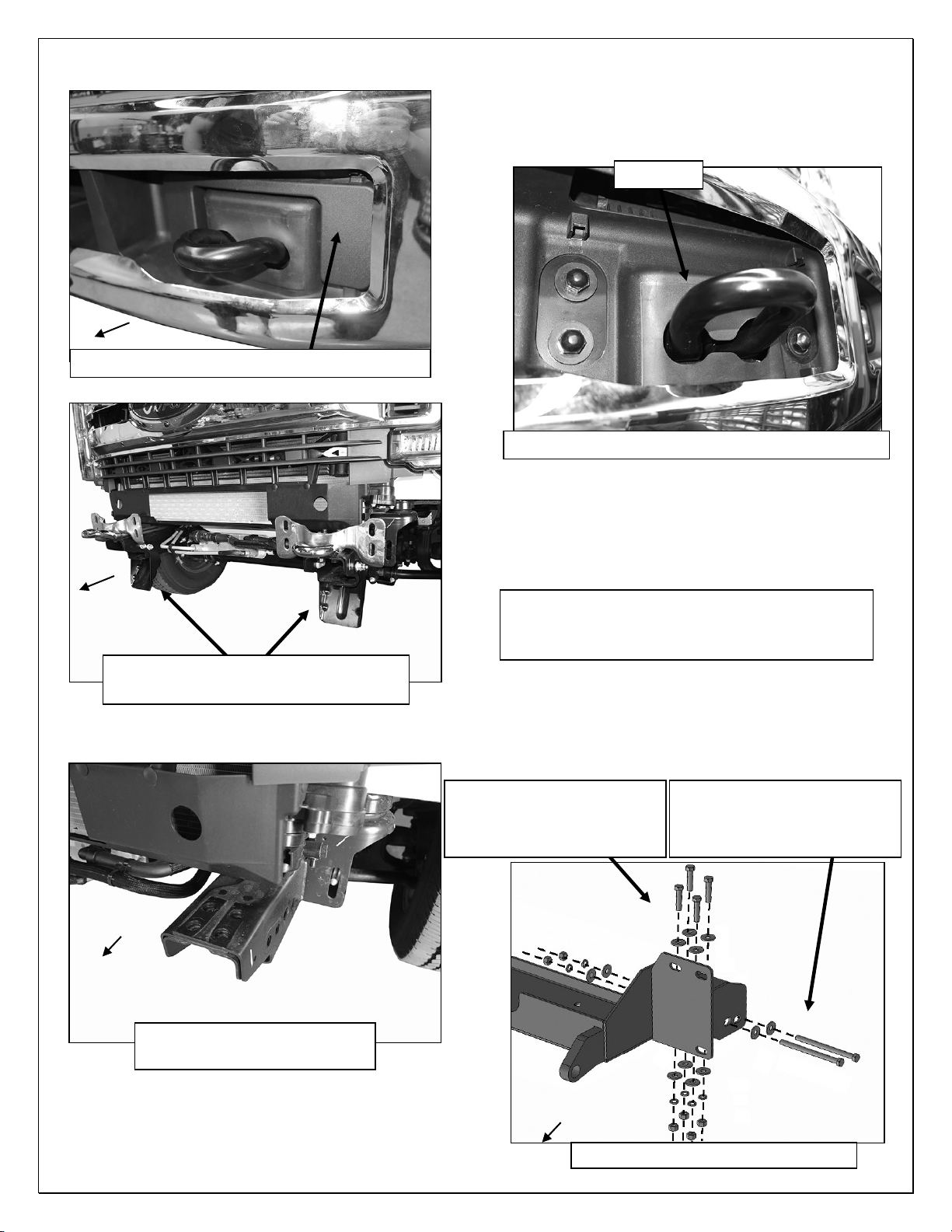
1. Remove the license plate and bracket. On models with factory fog lights, unplug both lights. Release
the wiring harness from the clips attached to the back of the bumper, (Figures 1 & 2). Move harness
away from bumper.
2. Remove the driver/left bumper support attached to the bumper frame bracket and outer end of the
bumper, (Figure 2). Remove the plastic covers from the tow hooks to uncover the bumper
bolts, (Figures 3 & 4). Repeat this Step to remove the passenger/right side bumper support
and cover.
3. Place blocks or jack stands under the front bumper to support it during mounting bolt removal. Once
the bumper has been safely supported, remove the factory bumper bolts, (Figure 4).
WARNING! Assistance is required to hold the bumper in place during bolt removal to prevent the
bumper from falling. Carefully slide the bumper off over the tow hooks, (Figure 5).
4. Remove the driver side tow hook assembly from the end of the frame, (Figure 6). Next, remove the
lower frame extension and double bolt plate from the end of the frame, (Figures 5 & 6). Repeat this
Step to remove the passenger side tow hook and lower frame extension.
5. Next, select the Winch Tray Bracket Assembly. Slide the assembly over the ends of the frame. Line
up the (2) slots in each side of the assembly with the holes in the side of the frame. Attach the
assembly to the frame with the included (2) 12mm x 170mm Hex Bolts, (4) 12mm Flat Washers, (2)
12mm Lock Washers and (2) 12mm Hex Nuts, (Figures 7 & 8). Leave hardware loose.
6. Attach the top of the Winch Tray assembly to the frame with (4) 12mm x 50mm Hex Bolts, (8) 12mm
Flat Washers, (4) 12mm Lock Washers and (4) 12mm Hex Nuts, (Figures 7 & 8). Leave hardware
loose. Repeat to attach the Winch Tray assembly to the passenger side of the frame.
7. If installing winch, (not included), attach the winch to the Winch Tray at this time. Winch must be
installed before Bumper is placed in position against Brackets. NOTE: Attach winch cable guide, (not
included), to Bumper assembly. Follow manufacturer’s instructions to properly attach the winch to the
vehicle’s electrical system.
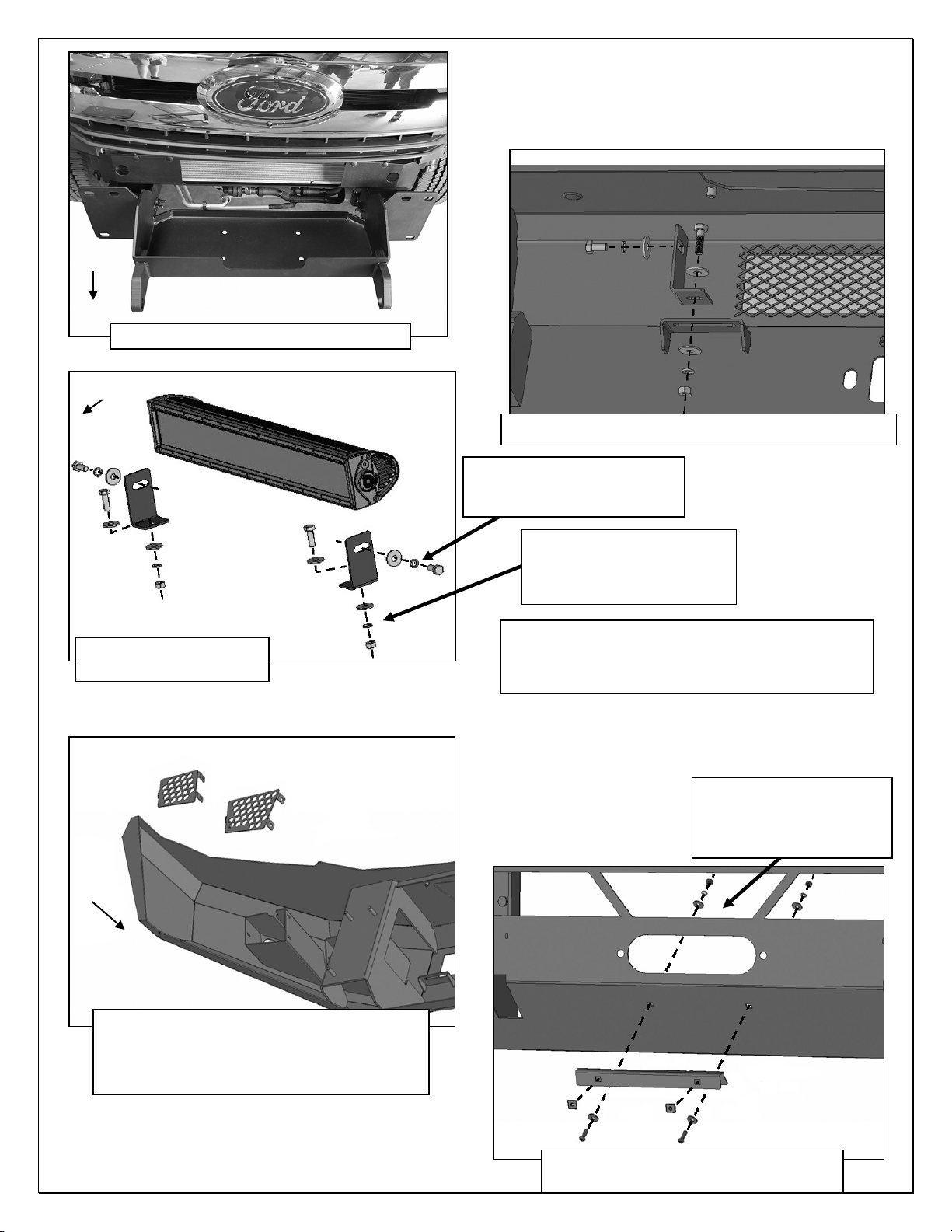
8. Optional Center LED light installation (sold separately). NOTE: Light must be installed before
Bumper Assembly is attached to the Winch Tray. IMPORTANT: Clearance between the bar style LED
light and the winch and/or winch tray must be determined before installing Bumper assembly.
a. Select the L/R “L” Brackets, (Figures 9 & 10). NOTE: “L” Brackets are offset for universal fitment
for most LED bar style lights. Attach the LED light assembly to the “L” Brackets with the included
(2) 8mm x 16mm Hex Bolts, (2) 8mm Lock Washers and (2) 8mm Flat Washers, (Figure 10). Do
Left and Right Offset
LED Light Brackets
(2) License
Plate Plugs
License Plate Bracket
Winch Tray and
Bracket Assembly

www
.
T
r
a
il
F
X
.
c
o
m
Page 3of 7 Rev 121218
not fully tighten hardware at this time. NOTE: “L” Brackets may require modification for hardware
larger than 8mm or use brackets supplied with light if possible.
b. Attach the light and brackets to the top of the (2) tabs on the back of the Bumper with the included
8mm x 25mm Hex Bolts, (4) 8mm Flat Washers, (2) 8mm Lock Washers and (2) 8mm Hex Nuts,
(Figure 10). Adjust light position and tighten hardware.
c. Follow light manufacturer’s instructions to wire the light to the vehicle’s electrical system once
Bumper has been fully installed.
9. LED light installation at ends of bumper (sold separately.
a. Insert light into opening and up to mounting slots. Check for clearance between front and back of
light. If necessary, remove the screens from the back of the openings, (Figure 11).
b. Follow the light manufacturer’s instructions to attach each light to slot in the top of the light
opening, (Figure 11). NOTE: On two light systems, attach the flood light to the outer slot and the
spot light to the inner slot.
c. Repeat the above steps for passenger side light installation.
d. Follow light manufacturer’s instructions to properly wire the light to the vehicle electrical system.
10. If front license plate is required, attach the License Plate Bracket to the holes in the bumper with the
included (2) 6mm x 20mm Button Head Screws, (4) 6mm Flat Washers and (2) 6mm Nylon Lock
Nuts, (Figure 12). Insert (2) Plastic Plugs into the square holes in the Bracket. Reuse the factory
screws to attach the license plate to the plastic plugs, (Figure 12).
11. With assistance, carefully position the Bumper Assembly up to the ends of the Winch Tray.
Temporarily support the weight of the Bumper. WARNING: To avoid possible injury or damage to the
vehicle, do not proceed until the bumper is fully and safely supported. Models with winch and/or LED
light, check for clearance before fully installing Bumper assembly.
12. Line up the (3) 10mm Studs in the driver side of the Bumper with the (3) holes in the Winch Tray.
Attach the Bumper to the Winch Tray with the included (3) 10mm Flat Washers, (3) 10mm Lock
Washers and (3) 10mm Hex Nuts, (Figures 13 & 14). Do not fully tighten hardware at this time.
Repeat to attach the passenger side of the Bumper to the Winch Tray.
13. Level and adjust the bumper and fully tighten all hardware.
14. Remove covers from top of Bumper for additional access if desired.
15. Do periodic inspections to the installation to make sure that all hardware is secure and tight.
To protect your investment, wax this product after installing. Regular waxing is recommended to add a
protective layer over the finish. Do not use any type of polish or wax that may contain abrasives that could
damage the finish. Mild soap may be used to clean the HD1 Front Bumper assembly.
Driver Side Installation Pictured
(Fig 1) Driver side lower frame extension and fog
light wire harness pictured from behind bumper
(Fig 2) Remove outer bumper support
Remove hardware attaching
bumper support brackets to frame
Lower frame
extension
www
.
T
r
a
il
F
X
.
c
o
m
Page 4of 7 Rev 121218
Driver Side Installation Pictured
WARNING! Do not remove bumper bolts
unless the bumper is properly supported on
blocks or stands or the bumper may fall.
(Fig 5) Remove tow hook assemblies
and lower frame extensions from frame
(Fig 6) Attach driver side of
Winch Tray assembly to frame
(Fig 7) Driver/left side of Winch Tray
(4) 12mm x 50mm Hex Bolts
(8) 12mm Flat Washers
(4) 12mm Lock Washers
(4) 12mm Hex Nuts
Tow hook
(Fig 3) Remove plastic cover around tow hook
Front
(Fig 4) Remove bumper bolts (driver side pictured)
(2) 12mm x 170mm Hex Bolts
(4) 12mm Flat Washers
(2) 12mm Lock Washers
(2) 12mm Hex Nuts
Front
Front
Front
www
.
T
r
a
il
F
X
.
c
o
m
Page 5of 7 Rev 121218
Driver Side Installation Pictured
(Fig 12) Push plastic plugs into holes
in Bumper for license plate if required
Front
(Fig 9) Universal LED Brackets (light not included)
WARNING! Do not crawl under bumper
unless the bumper is properly supported on
blocks or stands or the bumper may fall.
(2) 6mm x 20mm Button
Head Screws
(4) 6mm Flat Washers
(2) 6mm Nylon Lock Nuts
(Fig 11) Before installing Bumper, check for
clearance around lights (not included).
Remove screens for additional access or to
clear lights as needed
(2) 8mm x 16mm Hex Bolts
(2) 8mm Lock Washers
(2) 8mm Flat Washers
(Fig 10) Example of
center light installation
Front
(2) 8mm x 25mm Hex Bolts
(4) 8mm Flat Washers
(2) 8mm Lock Washers
(2) 8mm Hex Nuts
Right “L”
Bracket
Left “L”
Bracket
(Fig 8) Winch Tray Assembly installed
Front

www
.
T
r
a
il
F
X
.
c
o
m
Page 6of 7 Rev 121218
(Fig 13) Attach Bumper to Winch Tray Brackets
Complete Installation
(3) 10mm Flat Washers
(3) 10mm Lock Washers
(3) 10mm Hex Nuts
Front
(Fig 14) Driver/left side of Bumper and Bracket
(3) 10mm Flat Washers
(3) 10mm Lock Washers
(3) 10mm Hex Nuts
www
.
T
r
a
il
F
X
.
c
o
m
Page 7of 7 Rev 121218
FAQ’s
1. Hardware’s are not of correct size.
In GMC / Chevrolet truck model 2006 & up, customer needs to reuse the factory body bolts to install the bracket. If your vehicle is not
GMC / Chevrolet 2006 & up, ensure that holes are not partially covered with any plastic grommet or rust? If it is, remove the plastic
grommet & rust from the thread holes & re-try the installation.
2. Mounting Bracket are not getting Installed properly.
In some cases Illustration images shown in Installation manual may not be the exactly same as per actual vehicle images ,also if Driver /
Passenger side mounting brackets are very identical in the design, suggest referring Parts Identification guide to avoid fitment issue.
3. Products are thumping / rattling after installation.
Ensure that all required mounting brackets / hardware’s are installed & tighten correctly. Suggest using white lithium / regular grease
between the metal to metal contact surfaces.
4. Side Bar is not aligning with vehicle / Step Pads are not aligning with vehicle doors.
Side bar may be interchanged or mounting brackets are not installed at the correct position in the vehicle. Refer Parts identification guide.
5. Missing / Excess Hardware.
Recheck hardware count as per the part list.
6. Product not installing properly.
Ensure make model year, cab length and bed size of your vehicle is listed in the application. All installation steps are followed correctly.
No.
Parts Identification
1 Passenger / Right ‘Rear’ Bracket marked “
PR
”
2 Driver / Left ‘Rear’ Bracket marked “DR”
3
Passenger / Right ‘Center’ Bracket marked “PC”
4 Driver / Left ‘Center’ Bracket marked “DC”
5 Passenger / Right ‘Front’ Bracket marked “
PF
”
6 Driver / Left ‘Front’ Bracket marked “DF”
Note:
This guide is to identify the parts and not a reference for part count.
For part count, refer Parts List.
Product / Bracket image is representative and actual design may vary.
Check out these other TrailFX Products!! www.TrailFX.com
PRODUCT CARE
•Periodically check the product to ensure all fasteners are tight and components are intact.
•Regular waxing is recommended to protect the finish of the product.
•Use ONLY Non-Abrasive automotive wax. Use of any soap, polish or wax that contains an abrasive is detrimental and can scratch the
finish leading to corrosion.
•Aluminum polish may be used to polish small scratches and scuffs for Stainless Steel finish.
•Mild soap may be used to clean the product for both Stainless Steel and Black finish.
Keystone Automotive Operations Inc. (KAO) warrants this product to be free of defects in material and workmanship at the time of purchase by the
original retail consumer. KAO disclaims any other warranties, express or implied, including the warranty of fitness for a particular purpose or an
intended use. If the product is found to be defective, KAO may replace or repair the product at our option, when the product is returned prepaid,
with proof of purchase. Alteration to, improper installation, or misuse of this product voids the warranty. KAO’s liability is limited to repair or
replacement of products found to be defective, and specifically excludes liability for any incidental or consequential loss or damage.
Table of contents
Other TrailFX Automobile Accessories manuals

TrailFX
TrailFX A1018S/T User manual

TrailFX
TrailFX G9022B User manual

TrailFX
TrailFX A4004S User manual

TrailFX
TrailFX JL010RI User manual

TrailFX
TrailFX JTSB03 User manual

TrailFX
TrailFX R0023MK User manual

TrailFX
TrailFX A0057S/B User manual

TrailFX
TrailFX FX3017 User manual

TrailFX
TrailFX A0002S User manual

TrailFX
TrailFX BR010T User manual

TrailFX
TrailFX TFX5526 User manual

TrailFX
TrailFX TFX3521 User manual

TrailFX
TrailFX A7024S User manual

TrailFX
TrailFX JL010RF User manual

TrailFX
TrailFX A7100S/T User manual

TrailFX
TrailFX T0002B User manual

TrailFX
TrailFX A1006S/B User manual

TrailFX
TrailFX 22106ZX User manual

TrailFX
TrailFX 21020 Series User manual

TrailFX
TrailFX J048T User manual


