TrailFX RBV05B User manual
Visit www.trailfx.com or 1 (866) 638-4870 for Warranty Information / Tech Support / Product Updates
.
2021 Keystone Automotive Operations Inc. All Rights Reserved. 03/04/2022-R01 Page-1-9
APPLICATION: 2014-Current Dodge Ram Promaster Van 136"/159" wheel base (full size)
Assembly, Installation, Operation and
Maintenance Instructions
Running Board
Part Number:
RBV05B
60 - 180 minutes
Dealer / Installer: Provide a copy of these instructions to the end user of this product. These instructions
provide important operating and safety information for proper usage of this product.
Demonstrate the proper use of the product with the end user. Have the end user
demonstrate that they understand the proper use of the product.
End User: Read and follow all instructions included in this manual. Ask your Dealer / Installer for
assistance if you do not understand the proper use of the product. Never remove any
decals from the product. Failure to follow these instructions can result in injury or death.
WARNING
PARTS LIST
Qty Part Description Qty Part Description
1 Driver/left Side Running Board 12 8mm x 1.25mm x 25mm Hex Bolts
1 Passenger/right Side Running Board 6 8mm x 28mm OD x 3mm Flat Washers
1 Driver/Left Side Front Bracket 24 8mm x 16mm OD x 1.6mm Flat Washers
1 Driver/Left Side Rear Bracket 6 8mm Lock Washers
1 Driver/Left Side Front Support Bracket 6 8mm Hex Nuts
1 Passenger/Right Side Front Bracket 12 8mm Nylon Lock Nuts
3 Passenger/Right Side Center/Rear Brackets 6 6mm Double Bolt Plates
5 Passenger/Right Side Support Brackets (1-drv rear) 12 6mm x 22mm OD x 2mm Flat Washers
6 8mm x 1.25mm x 35mm Bolt Plates 12 6mm Lock Washers
6 8mm Plastic Retainers 12 6mm Hex Nuts
TORQUE SPECIFICATION
Size Torque Size Torque
6 MM 8.5 ft/lbs 8 mm 20 ft/lbs
Visit www.trailfx.com or 1 (866) 638-4870 for Warranty Information / Tech Support / Product Updates
.
2021 Keystone Automotive Operations Inc. All Rights Reserved. 03/04/2022-R01 Page-2-9
INSTALLATION PROCEDURE:
REMOVE CONTENTS FROM BOX. VERIFY ALL PARTS ARE PRESENT. READ INSTRUCTIONS CAREFULLY BEFORE
STARTING INSTALLATION. DRILLING IS REQUIRED. ASSISTANCE IS RECOMMENDED.
1. Start the installation under the driver side of the vehicle. Locate the factory hole in the side of the inner body panel, (Figures
1 & 3). IMPORTANT: Hole may be covered with rubber plug, sealing tape and/or heavy undercoating. Remove excess
undercoating from all mounting locations so that Brackets will install flat against body panel and pinch weld.
2. Select (1) 8mm Bolt Plate and (1) 8mm Plastic Retainer, (Figure 2). Thread the Retainer part way onto the Bolt Plate. Insert
the Bolt Plate into the hole and tighten the Retainer against the body panel, (Figure 3). IMPORTANT: The Plastic Retainer
is designed to prevent the Bolt Plate from falling into the body panel and to aid in Bracket installation.
3. Select the driver/left front Mounting Bracket. Attach the Bracket to the Bolt Plate with (1) 8mm x 28mm Large Flat Washer,
(1) 8mm Lock Washer and (1) 8mm Hex Nut, (Figure 4). Leave hardware loose at this time.
4. Select the Driver/Left Support Bracket, (Figure 5). Attach the Support Bracket to the front of the Mounting Bracket with (1)
8mm x 25mm Hex Bolt, (2) 8mm x 16mm Small Flat Washers and (1) 8mm Nylon Lock Nut, (Figure 6). Line up the top of
the Support Bracket with the outside of the pinch weld. Leave hardware loose at this time.
5. Move to the driver side rear mounting location. Locate the factory hole in the bottom of the floor panel, (Figure 7). Repeat
Steps 1—3 to attach the driver/left rear Bracket to the 8mm Bolt Plate, (Figure 8).
6. Select (1) of the (5) identical Support Brackets, (Figure 9). Attach the Support Bracket to the back of the rear Mounting
Bracket with (1) 8mm x 25mm Hex Bolt, (2) 8mm x 16mm Small Flat Washers and (1) 8mm Nylon Lock Nut, (Figure 10).
Line up the top of the Support Bracket with the outside of the pinch weld. Leave hardware loose at this time.
7. Carefully unwrap the Running Boards. Place the short driver side Running Board on top of the (2) Brackets. Select (2) 6mm
Double Bolt Plates, (Figure 11). Locate the channels in the bottom of the Running Board, (Figure 12). Insert the Bolt Plates
into the channels closest to the Brackets. Lift the Running Board up and guide the studs down through the Brackets.
8. Attach the Running Board to the Brackets with (4) 6mm Flat Washers, (4) 6mm Lock Washers and (4) 6mm Hex Nuts,
(Figure 13). NOTE: The Running Board is designed to fit close to the vehicle. It may be necessary to loosen the Bracket
hardware and tilt the Brackets downward to insert the Running Board between the Brackets and the body. Do not tighten
hardware at this time.
9. Level and adjust the Running Board and tighten the Bracket to Bolt Plate hardware only. Remove the Running Board.
Adjust the Support Brackets as necessary to move the top of the Brackets up to touch the bend in the pinch weld. Mark the
location of the (2) slots in the Support Brackets onto the outside of the pinch weld, (Figure 14).
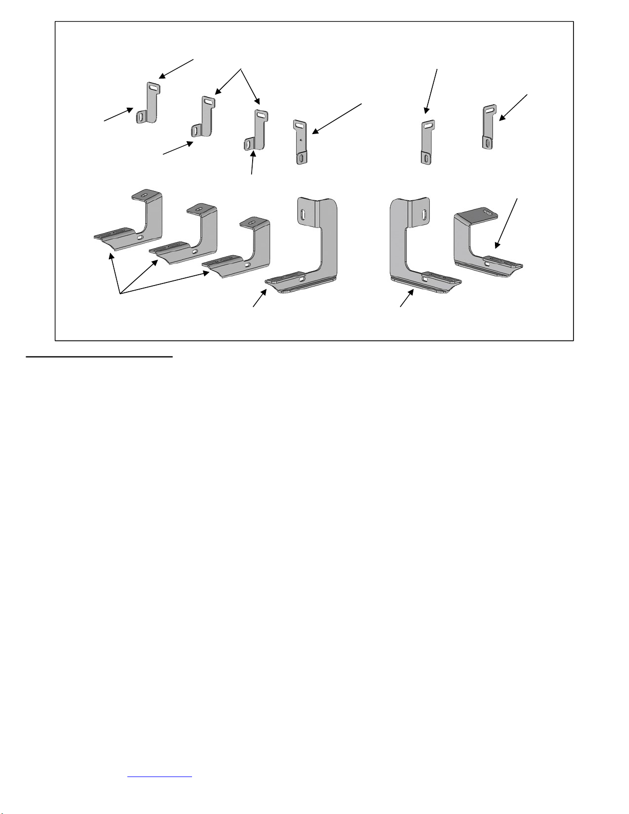
Driver/Left Front
Mounting Bracket
(3) Passenger/Right
Center/Rear Mounting
Brackets
Passenger/right Front
Mounting Bracket
Driver/Left Rear
Mounting Bracket
Support Bracket
(1 of 5)
Support Bracket
(2 of 5)
Unique Passenger
Front Support
Bracket Only
Passenger/right #2, #3
and Rear Mounting
Brackets (same)
Support Bracket
(3 of 5)
Support Bracket
(4 of 5)
Support Bracket
(5 of 5)

Visit www.trailfx.com or 1 (866) 638-4870 for Warranty Information / Tech Support / Product Updates
.
2021 Keystone Automotive Operations Inc. All Rights Reserved. 03/04/2022-R01 Page-3-9
10. 10. Use a 5/16” drill bit to drill (2) holes through the pinch weld for the front and rear Support Brackets. NOTE: Drill the
holes as far away from the bottom edge of the pinch weld as possible. IMPORTANT: Do not drill through the welds in the
pinch weld if possible.
10. Attach the top of the Support Brackets to the outside of the pinch weld with (2) 8mm x 25mm Hex Bolts, (4) 8mm x 16mm
Small Flat Washers and (2) 8mm Nylon Lock Nuts, (Figure 15). Reinstall the Running Board. Level, adjust and tighten all
hardware.
11. Move to the passenger side of the vehicle, (Figure 16). Repeat Steps 1—3 to attach the passenger side front Bracket,
(Figures 17 & 18). Repeat Step 6 to attach (1) of the (5) identical Support Brackets.
12. Continue to the #2 mounting location, (Figure 19). Repeat Steps 5 & 6 to attach the #2 Mounting Bracket, (Figure 20).
Repeat to install the #3 and #4 (rear) Brackets, (Figures 21—23).
13. Select the long passenger side running board. Select (4) 6mm Double Bolt Plates, (Figure 11). Locate the channels in the
bottom of the Running Board, (Figure 12). Insert the Bolt Plates into the channels closest to the Brackets. Lift the Running
Board up and guide the studs through the Brackets.
14. Attach the Running Board to the Brackets with (8) 6mm Flat Washers, (8) 6mm Lock Washers and (8) 6mm Hex Nuts,
(Figures 22 & 23).
15. Level and adjust the Running Board and tighten the Bracket to Bolt Plate hardware only. Remove the Running Board.
Adjust the Support Brackets as necessary to move the top of the Brackets up to touch the bend in the pinch weld. Mark the
location of the slots in the (3) Support Brackets onto the outside of the pinch weld, (Figures 20 & 21).
16. Repeat Steps 10 & 11 to drill and attach the (4) Support Brackets to the pinch weld.
17. Reinstall the Running Board. Level and adjust and tighten all hardware.
18. Do periodic inspections to the installation to make sure that all hardware is secure and tight.
To protect your investment, wax this product after installing. Regular waxing is recommended to add a protective layer over the finish. Do
not use any type of polish or wax that may contain abrasives that could damage the finish.
Mild soap may be used also to clean the Running Board.
IMPORTANT! Any cutting or drilling tool may break or shatter. Government regulations require safety glasses & equipment at
all times when cutting or drilling.
INSTALLATION IMAGES:
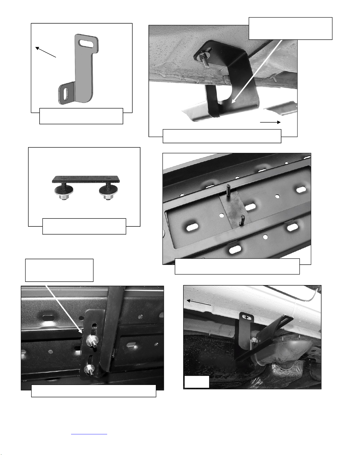
Driver/left Side Installation Pictured
(Fig 1) Driver side front and rear
mounting locations
(Fig 2) 8mm Bolt Plate
with Plastic Retainer
Front

Visit www.trailfx.com or 1 (866) 638-4870 for Warranty Information / Tech Support / Product Updates
.
2021 Keystone Automotive Operations Inc. All Rights Reserved. 03/04/2022-R01 Page-4-9
(Fig 3) Insert Bolt Plate into factory hole
(Fig 4) Driver side front Bracket pictured
(Fig 5) Driver/Left Support
Bracket (1 of 5)
Front
Front
Front
8mm Large Flat Washer
8mm Lock Washer
8mm Hex Nut
(Fig 6) Driver side front Support Bracket
Front
8mm x 25mm Hex Bolt
(2) 8mm Small Flat Washers
8mm Nylon Lock Nuts
(Fig 7) Driver side rear mounting location
(Fig 8) Driver side rear Bracket
8mm Flat Large Washer
8mm Lock Washer
8mm Hex Nut
Front
Visit www.trailfx.com or 1 (866) 638-4870 for Warranty Information / Tech Support / Product Updates
.
2021 Keystone Automotive Operations Inc. All Rights Reserved. 03/04/2022-R01 Page-5-9
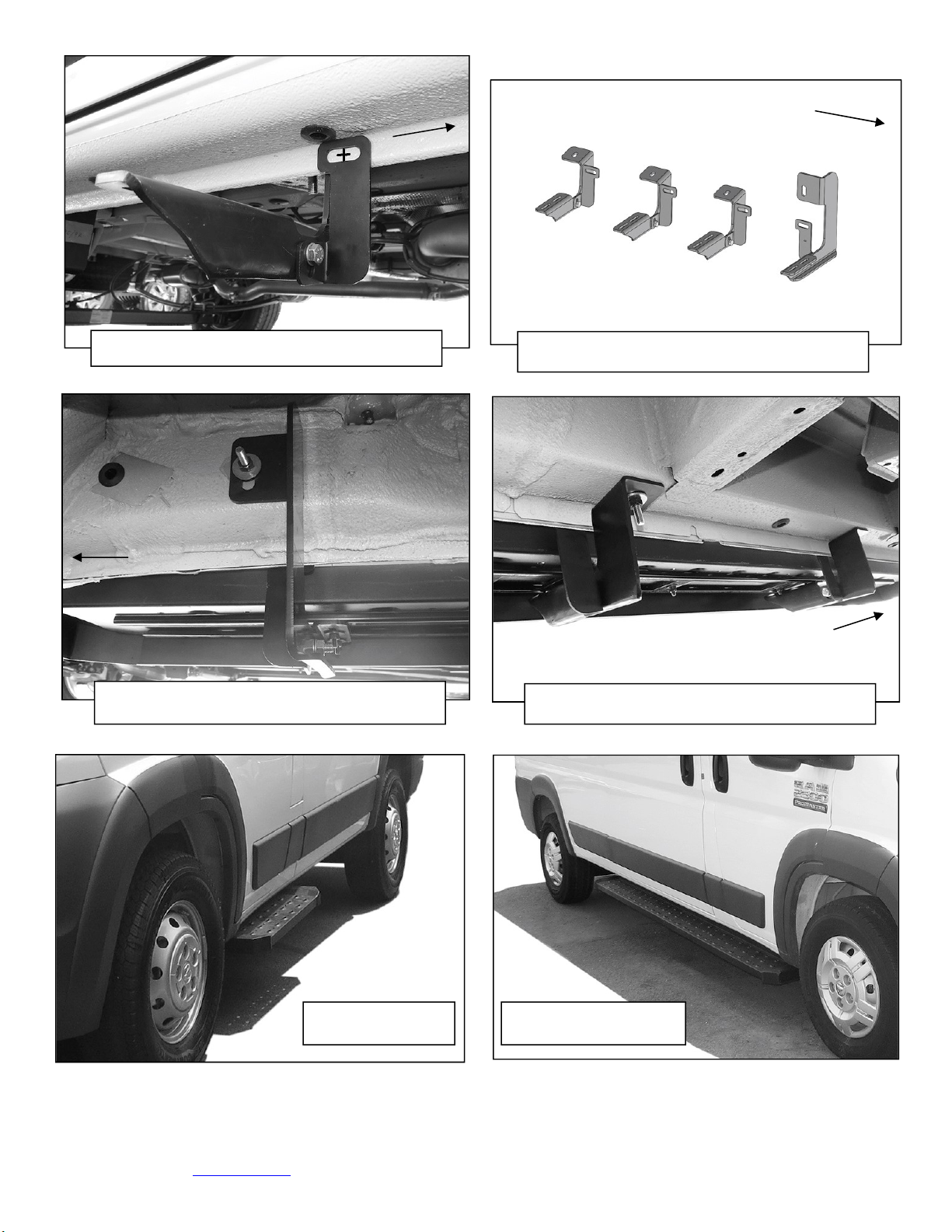
(Fig 9) Driver/Left Support
Bracket (2 of 5)
Front
(Fig 10) Driver side rear Support Bracket
Front
8mm x 25mm Hex Bolt
(2) 8mm Small Flat Washers
8mm Nylon Lock Nuts
(Fig 11) 6mm Double Bolt
Plate
(Fig 12) Insert 6mm Double Bolt Plates into
tracks on the bottom of the Running Board
(Fig 13) Attach Running Board to Brackets
(2) 6mm Flat Washers
(2) 6mm Lock Washers
(2) 6mm Hex Nuts
(Fig 14)
Front

Visit www.trailfx.com or 1 (866) 638-4870 for Warranty Information / Tech Support / Product Updates
.
2021 Keystone Automotive Operations Inc. All Rights Reserved. 03/04/2022-R01 Page-6-9
(Fig 15)
Front
Level and adjust the Running Board.
Temporarily remove the running board.
Mark and drill 5/16” hole through pinch
weld for each Support Bracket
Passenger/right Side Installation Pictured
(Fig 16) Passenger side mounting locations
(Fig 17) Passenger front mounting location
Front
Front
8mm Bolt Plate
Plastic Retainer
(Fig 18) Follow Figures (4-6) to attach the
Passenger/Right Front Mounting Bracket and
the Unique Support Bracket
Front
(Fig 19) Passenger side #2, #3 and rear
mounting locations
Front
(2) 8mm x 25mm Hex Bolts
(2) 8mm Lock Washers
(2) 8mm Flat Washers
Visit www.trailfx.com or 1 (866) 638-4870 for Warranty Information / Tech Support / Product Updates
.
2021 Keystone Automotive Operations Inc. All Rights Reserved. 03/04/2022-R01 Page-7-9
(Fig 20) Passenger side #2 Bracket installed
Front
(Fig 21) Passenger side Bracket layout w-
Support Brackets
Front
Front
Bracket
#2, #3 and rear
Brackets (same)
Front
(Fig 23) Passenger side #2 and #3 Brackets
installed-mark to drill through pinch weld
Rear
(Fig 22) Passenger side front installed-mark
to drill through pinch weld
Complete Driver
Side Installation
Complete Passenger
Side Installation

Visit www.trailfx.com or 1 (866) 638-4870 for Warranty Information / Tech Support / Product Updates
.
2021 Keystone Automotive Operations Inc. All Rights Reserved. 03/04/2022-R01 Page-8-9
PRODUCT CARE
• Periodically check the product to ensure all fasteners are tight and components are intact.
• Regular waxing is recommended to protect the finish of the product.
• Use ONLY Non-Abrasive automotive wax. Use of any soap, polish or wax that contains an abrasive is detrimental and can
scratch the finish leading to corrosion.
• Aluminum polish may be used to polish small scratches and scuffs for Stainless Steel finish.
• Mild soap may be used to clean the product for both Stainless Steel and Black finish.
FAQ’s
1. Hardware and mounting brackets are not aligning properly
Ensure that hardware is being used on the correct side of vehicle. In some cases, the hardware may appear same for driver and
passenger side but may alter the alignment of mounting location. Check mounting brackets for both sides.
2. Products are thumping / rattling after Installation
Ensure that all required mounting brackets / hardware’s are installed & tightened correctly.
Suggest using white Lithium / regular grease between metal-to-metal contact.
3. Missing / Excess Hardware
Recheck hardware count as per the part list.
4. Product not installing properly
Ensure the Year / Make / Model as well as cab and bed dimensions are correct for the application. Review all steps for installation to
ensure they were followed correctly.
5. Who should be contacted for questions regarding product / installation assistance?
www.trailfx.com / [email protected] or 1-(866) 638-4870

Visit www.trailfx.com or 1 (866) 638-4870 for Warranty Information / Tech Support / Product Updates
.
2021 Keystone Automotive Operations Inc. All Rights Reserved. 03/04/2022-R01 Page-9-9
Warranty Terms:
3 Year Limited Warranty:
TrailFX and Keystone Automotive Operations Inc. make no guarantees or warranties for products not
manufactured by Keystone Automotive Operations Inc. Such products are covered solely under any
applicable warranty of the manufacturer. It is always recommended that the operating instructions and
warranty instructions provided by the manufacturer are followed.
Keystone Automotive Operations Inc. warrants its products to be free from manufacturing and material
defects to the original purchaser for the length of warranty stated above from the date of retail purchase.
If any products are found to have a manufacturing or material defect, the product will be replaced or
repaired at the option of TrailFX and Keystone Automotive Operations Inc. with proof of purchase by the
original purchaser. The original purchaser shall pay all transportation and shipping costs associated with
the return of the defective product and the defective product shall become the property of Keystone
Automotive Operations Inc.
The Warranty applies to Keystone Automotive Operations Inc. products used for individual and
recreational purposes. Commercial usage of the Keystone Automotive Operations Inc. products limits the
warranty to 90-days from date of purchase.
The Warranty applies only to Keystone Automotive Operations Inc. products which are found to be
defective in manufacturing or material. This warranty does not apply to normal wear and tear of the finish
placed on Keystone Automotive Operations Inc. products.
TrailFX and Keystone Automotive Operations Inc. are not responsible for any labor costs incurred for
removal or replacement of the defective product.
TrailFX and Keystone Automotive Operations Inc. are not responsible for repair or replacement of any
product under the limited warranty where the product was improperly installed, misapplied, altered,
abused, neglected, overloaded, misused or damaged as a result of an accident, including any use of the
product not in accordance with all product operating and safety instructions.
Without limiting the generality of the foregoing, TrailFX and Keystone Automotive
Operations Inc. shall under no circumstances be liable for any incidental or consequential loss or damage
whatsoever arising out of, or in any way relating to any such breach of warranty or claimed defect in, or
non-performance of the products. Some states do not allow the exclusion or limitation of incidental or
consequential damages, so the above exclusion or limitation may not apply to you.
This limited warranty gives you specific legal rights, and you may also have other rights that vary from
state to state.
Table of contents
Other TrailFX Automobile Accessories manuals

TrailFX
TrailFX A4012S User manual

TrailFX
TrailFX TG60X User manual

TrailFX
TrailFX Tonneau User manual

TrailFX
TrailFX BR012T User manual

TrailFX
TrailFX RBA023TI User manual

TrailFX
TrailFX ARBV002B User manual

TrailFX
TrailFX FHDNW002TI User manual

TrailFX
TrailFX JL010RI User manual

TrailFX
TrailFX FX3017 User manual

TrailFX
TrailFX T0002B User manual

TrailFX
TrailFX FX3002 User manual

TrailFX
TrailFX A1018S/T User manual

TrailFX
TrailFX RBW10B User manual

TrailFX
TrailFX TFX3521 User manual

TrailFX
TrailFX A0057S/B User manual

TrailFX
TrailFX A7099S User manual

TrailFX
TrailFX 968 User manual

TrailFX
TrailFX TFX1404 User manual

TrailFX
TrailFX J048T User manual

TrailFX
TrailFX NERF BAR A0025S User manual


