TRAK 3ntr Series Manual

TRAK®3ntr 3D Printers
Printer & MMS Initial Set-Up & Calibration Guide
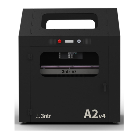
Covers Current Models:
•3ntr A2
•3ntr A4
•3ntr MMS v1/v2
2615 Homestead Place
Rancho Dominguez, CA 90220-5610 USA
T | 310.608.4422 |F | 310.764.2668
Service Department: 800.367.3165
e-mail: sales@trakmt.com | service@trakmt.com | web: www.trakmt.com
Document: P/N 32232
Version: 010320

Copyright ©2019, Southwestern Industries, Inc. All rights are reserved. No part of this publication may
be reproduced, stored in a retrieval system, or transmitted, in any form or by any means, mechanical,
photocopying, recording or otherwise, without the prior written permission of Southwestern Industries,
Inc.
While every effort has been made to include all the information required for the purposes of this guide,
Southwestern Industries, Inc. assumes no responsibility for inaccuracies or omission and accepts no
liability for damages resulting from the use of the information contained in this guide.
All brand names and products are trademarks or registered trademarks of their respective holders.
Southwestern Industries, Inc.
2615 Homestead Place
Rancho Dominguez, CA 90220
Phone 310-608-4422 Fax 310-764-2668
Service Department
Phone 800-367-3165 Fax 310-886-8029

i
TRAK Machine Tools
Southwestern Industries, Inc.
TRAK 3ntr 3D Printers –Printer & MMS Initial Set-up & Calibration Guide
Table of Contents
1Introduction ...............................................................1
1.1 Initial Set-Up & Calibration Guide Scope ............................................. 1
1.2 Initial Printer Set-Up & Calibration Checklist ...................................... 2
2Safety..........................................................................3
2.1 Safety Precautions ................................................................................ 3
3Uncrate & Unpack Printer/MMS Unit ..........................5
3.1 Select & Prepare a Suitable Location for Printer & MMS Unit.............. 5
3.1.1 Site Preparation Guide.................................................................... 5
3.1.2 Lifting and Moving Printer .............................................................. 7
3.2 Uncrate & Unpack MMS Unit (If Applicable) ........................................ 7
3.3 Uncrate & Unpack Printer ..................................................................... 8
3.4 Locate Printer and MMS Unit/Printer Stand in Final Location ............. 8
4Printer Orientation......................................................9
4.1 Printer Identification Guide: Front, Rear, and Side Views ................... 9
4.2 Front Panel Controls ........................................................................... 11
5Install HEPA Filter ....................................................12
5.1 Install HEPA Filter (Common to MMSV2 & External Filter Unit) ........ 12
5.2 Complete HEPA Filter Installation (for MMS V2 Only) ....................... 18
5.3 Complete HEPA Filter Installation (External HEPA Filter Unit Only) . 19
6Remove Printed Part.................................................21
7Check & Fill Coolant Level.........................................24
8Electrical Connections ..............................................25
8.1 Verify Input Power Source Voltage/Phase......................................... 25
8.2 MMS Unit 220V Electrical Power Connection ..................................... 26
8.3 Standard 3ntr 220V Electrical Power Connections............................. 28
8.4 Wiring a Printer or MMS Power Cable for 220V Single Phase............ 29
8.5 3ntr A4 printer with 120 VAC US Power Connection.......................... 30

ii
TRAK Machine Tools
Southwestern Industries, Inc.
TRAK 3ntr 3D Printers –Printer & MMS Initial Set-up & Calibration Guide
9Power on the Printer and MMS Unit (If applicable)..31
9.1 Power on the MMS Unit (If applicable) .............................................. 31
9.2 Power on the Printer........................................................................... 31
10 Operate the Printer Manually Using Front Panel
Controls ...........................................................................33
10.1 LCD Display and Control Menus Overview ......................................... 33
10.1.1 LCD Display –Idle Machine Menu ................................................ 33
10.1.2 LCD Display –Information Screen................................................ 33
10.1.3 LCD Display –Prepare Menu......................................................... 34
10.2 Operate the Printer Manually Using LCD and Front Panel Controls... 35
10.2.1 Move Axis Function ....................................................................... 35
10.2.2 Auto Home Function ..................................................................... 37
10.2.3 Disable Steppers ........................................................................... 38
11 Load Filament/Materials...........................................39
11.1 Load Filament to Back of Printer ........................................................ 39
11.2 Filament Care/Storage ....................................................................... 45
12 Purge Nozzle/Filament .............................................48
13 Clean Nozzles............................................................51
13.1 Clean Nozzle Procedure Overview:..................................................... 51
13.2 Unload Filament Using Change Filament Function............................. 51
13.3 Load Cleaning Filament ...................................................................... 55
13.4 Nozzle Cleaning (Automated Function).............................................. 57
14 Calibrate Printer .......................................................60
14.1 Installation & Initial Set-Up Calibrations ........................................... 60
14.2 Z Offset................................................................................................ 61
14.2.1 Z Offset Calibration Print .............................................................. 61
14.2.2 Z Offset –Read, Enter & Save....................................................... 63
14.3 XY Offset ............................................................................................. 64
14.3.1 XY Offset Calibration Print............................................................ 65

iii
TRAK Machine Tools
Southwestern Industries, Inc.
TRAK 3ntr 3D Printers –Printer & MMS Initial Set-up & Calibration Guide
14.3.2 XY Offset –Read, Enter & Save .................................................... 67
14.4 Z Nozzle Comparison -3 Nozzles Relative Z Position Calibration....... 71
14.5 Plate Leveling –User Procedure......................................................... 76
14.6 Z Nozzle Leveling Check –Calibration Print....................................... 77
14.7 Cubes - Calibration Test Print............................................................ 78
15 Print Parts.................................................................79
15.1 Print Parts from an SD Card................................................................ 79
15.2 Stop/Pause Printing ........................................................................... 82
15.3 Tune Menu –Adjust Process Parameters Mid-Print........................... 82
15.4 Maintain the printer for subsequent prints ........................................ 83
16 Set-Up and Install Printer Server .............................84
16.1 Introduction to Print Server ............................................................... 84
16.2 Assemble, Connect, and Start-Up Printer Server ............................... 84
16.3 Configure Printer Port......................................................................... 88
16.4 Archive Factory Firmware Settings .................................................... 92
17 MMS Unit Set-Up, Calibration, & Operation ..............98
17.1 MMS Overview .................................................................................... 98
17.2 MMS Unit Installation, Set-Up & Calibration...................................... 98
17.3 Complete Connections & Power ON the MMS Unit............................. 98
17.4 Install & Connect Server within the MMS Unit................................... 98
17.5 MMS Server Connection & Set-Up .................................................... 104
17.6
Zero the Cabinet
.............................................................................. 106
17.7
Calibrate the Cabinet
...................................................................... 107
17.8 MMS PTFE Tube Material Handling Installation ............................... 107
17.9 Install the Desiccant ......................................................................... 113
18 Operate, & Maintain the MMS Unit ........................ 115
18.1 MMS Touch Screen Control............................................................... 115
18.2 MMS Dashboard ................................................................................ 115
18.2.1 Accessing the MMS Dashboard over a network.......................... 117
18.3 Loading Filament/Material into the MMS Unit ................................. 117

iv
TRAK Machine Tools
Southwestern Industries, Inc.
TRAK 3ntr 3D Printers –Printer & MMS Initial Set-up & Calibration Guide
18.4 Controlling Relative Humidity (RH) within MMS Cabinet ................ 119
18.5 Update the MMS Firmware ............................................................... 120

1
TRAK Machine Tools
Southwestern Industries, Inc.
TRAK 3ntr 3D Printers –Printer & MMS Initial Set-up & Calibration Guide
1Introduction
Congratulations! Whether you purchased a TRAK 3ntr A2 or A4, you have an industrial-grade, 3D printer
that will produce high quality, functional parts, using an accurate and repeatable FFF print process, at low
cost per part.
TRAK 3ntr 3D Printers offer:
•An open materials platform enabling selection of a wide range of materials
•Complete flexibility in tailoring/tuning process settings and part characteristics
•Temperature controlled build chambers and printer plates
oNozzles up to 840° F (450°C)
oBed Up to 320° F (160° C)
oChamber up to 194° F (90° C)
•Generous build capacity/volume
oPrint Parts up to 24”x13”x19” for the A2
oPrint Parts up to 12”x7.5”x 8” for the A4
•Simultaneously prints 2 or 3 different print materials
•Integrated camera offering remote web monitoring
•Optional Material Management System to protect expensive environmentally sensitive materials
•KISSlicer software that converts STL files to printer ready g-code programs
1.1 Initial Set-Up & Calibration Guide Scope
This Initial Set-Up & Calibration Guide covers the basic steps required to set-up, calibrate, and operate a
new TRAK 3ntr A2/A4 printer and optional MMS unit from uncrating through to printing test parts. These
basic steps are outlined in the Initial Printer Set-Up & Calibration Checklist, below. Advanced set-up,
printer re-configuration, and repair maintenance procedures are not included within this guide.
This guide contains instructions to operate the TRAK 3ntr A2/A4 3D printers to simplify initial set-up and
calibration for factory trained technicians. It is not intended for customer use. Upon successful
completion of the initial set-up, calibration, and test prints, the customer should be encouraged to use
the simple and straightforward Printer & MMS Operation Quick Start Guide to get started, and the (full)
Printer & MMS Guide for those topics not covered in the QS Guide.
NOTE - The completeness and level of detail for set-up, calibration, operation, and maintenance
procedures within this guide is limited. Where additional information is required please consult the (full)
Printer & MMS Guide, Maintenance Manual, or specific procedure/work instruction documents.
CAUTION - Section 2 contains important safety information, it is highly recommended that all personnel
and operators review and understand this information before starting. Only qualified and trained
operators should use this Initial Set-Up & Calibration Guide.

2
TRAK Machine Tools
Southwestern Industries, Inc.
TRAK 3ntr 3D Printers –Printer & MMS Initial Set-up & Calibration Guide
1.2 Initial Printer Set-Up & Calibration Checklist
Follow the checklist when installing a printer. Click on the Hyperlinks to jump to the
procedure/instructions for an individual step in the process.
TRAK 3NTR Initial Printer Set-up & Calibration Checklist
1. Safety Precautions
2. Uncrate & Unpack Printer/MMS Unit
3. Printer Orientation
4. Install HEPA Filter
5. Remove Printed Part
6. Check and Fill Coolant
7. Electrical Connections
8. Power ON the Printer/MMS Unit
9. Operate the Printer Manually Using LCD and Front Panel Controls
10. Load Filament to Back of Printer
11. Purge Nozzles/Filament
12. Clean Nozzles (Not Typically Required on Initial Set-up)
13. Calibrate Printer
14. Print Parts
15. Set-Up and Install Print Server
16. Set-Up and Calibrate MMS Unit (if applicable)
17. Operate and Maintain MMS Unit (if applicable)

3
TRAK Machine Tools
Southwestern Industries, Inc.
TRAK 3ntr 3D Printers –Printer & MMS Initial Set-up & Calibration Guide
2Safety
The safe set-up, calibration, and operation of your TRAK 3ntr 3D printer depends on its proper use and
precautions taken by each operator. If these activities are performed incorrectly, there are risks, not
limited to, electric shock, pinch/crush, burns, inhalation of fumes/debris that can cause serious injury or
death.
Read and follow this Initial Set-Up & Calibration Guide. Understand the printer operation and safety
precautions before setting up, calibrating, or operating the 3D printer.
•Always wear safety glasses and safety shoes.
•Always stop the printer before opening the access door and reaching into the printer.
•Always allow the printer, printer surface plate and workpiece to cool adequately before reaching
into the printer.
•Have a qualified electrician make all electrical connections and cable wiring
•Never wear gloves, rings, watches, long sleeves, neckties, jewelry, or other loose items when
operating the printer.
2.1 Safety Precautions
1) Do not operate this machine before the TRAK 3ntr Safety, Installation, Maintenance, Service and
Parts List Manual, and the Safety, Programming, Operating & Care Manual have been studied and
understood.
2) Do not run this machine without knowing the function of every control key, button, knob, or
handle. Ask your supervisor or a qualified instructor for help when needed.
3) Protect your eyes. Always wear approved safety glasses (with side shields) .
4) Allow the machine to cool before reaching into it for any reason. The printer bed, printer surface
plate, printed part, extruders/nozzles, and other printer interior components can reach very high
temperatures and cause serious burns.
5) Don't get caught in moving parts. Before operating this machine remove all jewelry including
watches and rings, neckties, and any loose-fitting clothing.
6) Keep your hair away from moving parts. Wear adequate safety headgear.
7) Protect your feet. Wear safety shoes with oil-resistant, anti-skid soles, and steel toes.
8) Take off gloves before you start the machine. Gloves are easily caught in moving parts.
9) Remove all tools (wrenches, check keys, etc.) from the machine before you start. Loose items
can become dangerous flying projectiles.
10) Never operate a 3D printer after consuming alcoholic beverages, or taking strong medication, or
while using non-prescription drugs.
11) Protect your hands. Stop the printer bed movement and extruder translation mechanism:
a. Before opening the printer access door
b. Before reaching into the machine for any reason
c. Before changing parts
d. Before removing the printer bed tray, printed parts, or filament debris
e. Before you make an adjustment to the extruder, nozzles or any interior mechanism.
12) Protect your eyes and the machine as well. Don't use a compressed air hose to remove the
debris or clean the machine.
13) Stop and disconnect the machine before you perform maintenance and calibration operations.
14) Keep work area well lighted. Ask for additional light if needed.
15) Do not lean on the machine while it is running.
4
TRAK Machine Tools
Southwestern Industries, Inc.
TRAK 3ntr 3D Printers –Printer & MMS Initial Set-up & Calibration Guide
16) Prevent slippage. Keep the work area dry and clean. Remove obstacles of any kind around the
machine.
17) Avoid getting pinched in places where the printer bed or extruder arm movement can cause a
crush or pinch injury
18) Do not operate the printer with the printer access door open or any of the windows or service
access panels removed.

5
TRAK Machine Tools
Southwestern Industries, Inc.
TRAK 3ntr 3D Printers –Printer & MMS Initial Set-up & Calibration Guide
3Uncrate & Unpack Printer/MMS Unit
The first steps to get started with your new TRAK 3ntr A2/A4 printer are described in this section. The
process will vary if you are using a TRAK supplied 3ntr Printer stand, MMS unit, or some other
table/bench for the printer.
3.1 Select & Prepare a Suitable Location for Printer & MMS Unit
Review the requirements for Printer & MMS Unit to select a suitable location before unpacking.
3.1.1 Site Preparation Guide
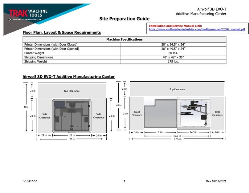
Space & Weight Requirements:
A2 Printer
•Dimensions = 37” x 32”/61.5” door
closed/open
•Height = 44.3”/72-78.3” On Stand/MMS Unit
•Net (approx.) Weight = 242 lbs.
•Shipping (approx.) Weight = 498 lbs.
•Shipping Dimensions 42”x 36”x 53”
•4 levelling screws are provided
MMS Unit
•Dimensions = 37” x 31.5”/88.5” doors
closed/open
•Height = 34.2”
•Net (approx.) Weight = 250 lbs. (approx.)
•Shipping (approx.) Weight = 425 lbs.
•Shipping Dimensions = 46” x 39” x 43”
•Mounted on locking casters/wheels
NOTE: A minimum 24” clearance on both sides, top, front, and rear (beyond Doors OPEN dimension of
printer/MMS Unit) is required for materials loading, service, and repair access.
NOTE: A solid and level foundation is required for printer and MMS
Electrical
A2 Printer
•220/230 VAC 15A power required for A2
Printer.
Note: Also requires 3x 110/120 VAC 15A
60 Hz external power for Print Server,
External HEPA filter unit, optional display
A2 Printer & MMS Unit
•220/230 VAC 15A single connection
required for A2 Printer and MMS Unit (A2
Printer plugs to MMS, MMS plugs to
external power)
•Print Server & HEPA filter unit (no external
power required for MMS V2)
NOTE: For shops with 440 VAC, a step-down transformer to 220 VAC must be used. The
transformer must be sized to carry a loadof 15 amps minimum.
Air
•Not required
Environmental
•Ambient Operating Temperature 16-32°C/61-90°F
•Storage Operating Temperatures 5--40°C/41-104°F

6
TRAK Machine Tools
Southwestern Industries, Inc.
TRAK 3ntr 3D Printers –Printer & MMS Initial Set-up & Calibration Guide
Figure 3.1.1 Printer & MMS Dimensions: Front View
Figure 3.1.2 Printer & MMS Dimensions: Side View with Open/Closed Doors

7
TRAK Machine Tools
Southwestern Industries, Inc.
TRAK 3ntr 3D Printers –Printer & MMS Initial Set-up & Calibration Guide
3.1.2 Lifting and Moving Printer
Figure 3.1.3 Moving Printer with Fork Truck (Secured to Pallet)
3.2 Uncrate & Unpack MMS Unit (If Applicable)
1) Use a fork truck to move the MMS unit as close as possible to the final location before
uncrating or removing from the pallet. The MMS unit has wheels and can be rolled on flat
level surfaces as needed.
2) Remove shipping screws holding top portion of MMS shipping crate to base
3) Lift off the top portion of the shipping crate from base
4) Remove ratchet straps
5) Set-Up a table or desk nearby for placing the printer/MMS/print server components during
the unpacking and set-up process.
6) Place materials from on top of MMS and place on a table
7) Remove protective bubble wrap and foam protection from MMS
8) Roll MMS Unit off the shipping pallet and on to the floor
9) Open access door to MMS. Remove the contents and place on a table (You may elect to wait
to perform this step later, such as after the printer has been placed on the MMS and when
ready to install the HEPA filter)
10) Remove protective plastic from MMS windows
CAUTION!
The A2 Printer should be moved by forklift or pallet jack ONLY when mounted on a pallet.
•The printer will be damaged if moved by forklift without the pallet attached.
•Once the pallet has been removed from the printer it must be moved by hand.
•Orient the printer with the sides or front facing the fork truck - The feeder mechanism and filament
spool holders on the rear of the printer protrude and can be damaged
•3 or 4 people are required move the A2 printer by hand - lifting it onto the printer stand, table, or
MMS.

8
TRAK Machine Tools
Southwestern Industries, Inc.
TRAK 3ntr 3D Printers –Printer & MMS Initial Set-up & Calibration Guide
3.3 Uncrate & Unpack Printer
CAUTION - After uncrating printer, DO NOT lift printer directly with forklift or slings. The printer
calibration and/or printer housing will be damaged if excessive force is exerted at any location other than
the four printer feet. Lift by hand with 3 or preferable 4 people if necessary. Replace printer onto
shipping pallet before using fork truck or lift.
1) Use a fork truck to move the printer unit as close as possible to the final location before
uncrating or removing from the pallet. The printer has fixed feet (not casters) thus must be
lifted and carried to its final position.
2) Remove shipping screws holding top portion of printer shipping crate to base
3) Lift off the top portion of shipping crate from base
4) Remove contents of printer and place on table.
5) Remove protective wrapping from outside printer
6) Open the access door to the printer bed and identify the protective materials and film at all
locations inside. Remove protective materials and plastic film from all printer windows and
access doors.
NOTE - Protective film must be removed or it will melt from the heat during the printing
process, causing damage to the printer.
3.4 Locate Printer and MMS Unit/Printer Stand in Final Location
If doing so, ensure the table or stand is rated for the weight of the printer and materials (A2=50 kg/A4 =
130 kg), is sufficiently flat, properly leveled, and is sturdy enough to prevent movement or vibration
during printing.
1) Move MMS Unit or Printer stand to desired location.
2) Lock wheels on MMS Unit or Printer Stand to prevent movement.
3) Get 3 or 4 people to lift the printer.
4) Place printer on MMS Unit/Printer Stand

9
TRAK Machine Tools
Southwestern Industries, Inc.
TRAK 3ntr 3D Printers –Printer & MMS Initial Set-up & Calibration Guide
4Printer Orientation
In this section, you will meet your new TRAK 3ntr 3D printer. After uncrating, please take a moment to
identify the important components of the printer before starting the set-up process.
4.1 Printer Identification Guide: Front, Rear, and Side Views
1) Emergency -E-STOP
Button. Powers ON
and OFF the Printer
2) LCD Display –Use for
printer control and
printing information
3) Jog Wheel and Black
Selector Button
4) Printer Door –Locking
Handle
5) Tank Port –Coolant
Check & Fill Location
Figure 4.1.1 Printer Front View

10
TRAK Machine Tools
Southwestern Industries, Inc.
TRAK 3ntr 3D Printers –Printer & MMS Initial Set-up & Calibration Guide
1) SD Card Port: Insert SD
card with print (g-code
files).
2) USB Port for PC or Print
Server connection.
3) Filament Feeders –Feed
mechanism for extruders
#1,#2, #3.
4) AC Inlet –Printer Power
Cord plugs in here.
Power On-OFF switch.
5) Spool Holders –Filament
Spools are mounted here
for Extruders #1, #2, #3.
Figure 4.1.2 Printer Rear View
1) VENT –Print fume
extraction port. Remove
plate and install HEPA
filter elbow/hose here.
2) Feeder PR –Feeder
pressure knob, adjusts
filament feeder pressure.
3) Handle –engages or
releases filament feeder
(engaged position shown)
4) AC Inlet –Printer Power
Cord plugs in here.
Power On-OFF switch.
5) Collar –Filament Spools
are mounted here for
Extruders #1, #2, #3.
Figure 4.1.3 Printer Side View

11
TRAK Machine Tools
Southwestern Industries, Inc.
TRAK 3ntr 3D Printers –Printer & MMS Initial Set-up & Calibration Guide
4.2 Front Panel Controls
All relevant machine duties can be performed using the printer front panel controls. Front panel controls
consist of a power/E-Stop button, LCD display screen, jog wheel, and black selector button.
•Power E-Stop button –Push in to Emergency STOP printer. Pull with clockwise turn to power ON
the printer.
•LCD Display –Displays printer information, status, control menus.
•Jog Wheel –Rotate in either direction to navigate menus, change values, control printer
•Black Jog Wheel Button –Push to select/initiate
Figure 4.2.1 Printer Front Panel Controls
Printer manual operation and control is performed by navigating through various menus that appear on
the LCD screen using the jog wheel to scroll up/down, increase/decrease a value, and pressing the black
jog wheel button to select/initiate.

12
TRAK Machine Tools
Southwestern Industries, Inc.
TRAK 3ntr 3D Printers –Printer & MMS Initial Set-up & Calibration Guide
5Install HEPA Filter
In this section, we will install/connect the HEPA filter Unit. Proper connection is required to remove
contaminants and maintain printer chamber temperatures during printing.
5.1 Install HEPA Filter (Common to MMSV2 & External Filter Unit)
NOTE –The final steps of HEPA Filter installation differ if; A) using an MMS V2 Unit that incorporates a
permanently affixed, internal HEPA filter unit OR B) if using a printer stand or no MMS unit. Determine
which instructions Section 5.2 (MMS2 V2) or Section 5.3 (External HEPA Filter Unit) are applicable and
follow them for completion.
Figure 5.1.1 HEPA filter unit within MMS V2
1) If using an external HEPA filter unit, then locate the air filter package including filtering unit,
filter cartridge, and power supply. Not applicable for MMS V2

13
TRAK Machine Tools
Southwestern Industries, Inc.
TRAK 3ntr 3D Printers –Printer & MMS Initial Set-up & Calibration Guide
Figure 5.1.2 External HEPA Filter components after assembly
2) Locate the air filter hose within the MMS unit and the 90-degree adapter elbow packaged
within the Print Server box.
3) Get tools including a 2.5mm hex driver (Set included with printer) and 7mm socket.
Figure 5.1.3 Tools for HEPA Filter installation
4) Remove the printer front window/cover plate to gain access to the nuts holding the rear filter
hose cover plate. Remove Qty. 4 of 2.5mm screws

14
TRAK Machine Tools
Southwestern Industries, Inc.
TRAK 3ntr 3D Printers –Printer & MMS Initial Set-up & Calibration Guide
Figure 5.1.4 Front Printer cover & screws (A4 Printer Shown)
5) Proceed to remove the rear cover plate (blanking plate for HEPA filter tube) using a 7mm
socket to hold the nuts from the inside of the left rear upper corner of machine
Figure 5.1.5 Blanking Plate cover & screws for removal
Other manuals for 3ntr Series
7
This manual suits for next models
4
Table of contents
Other TRAK 3D Printer manuals

TRAK
TRAK 3ntr Series User manual

TRAK
TRAK 3ntr Series Programming manual

TRAK
TRAK 3ntr Series User manual

TRAK
TRAK 3ntr Series User manual

TRAK
TRAK 3ntr A2 Programming manual

TRAK
TRAK Airwolf 3D EVO-T Operating instructions

TRAK
TRAK 3ntr Series User manual

TRAK
TRAK Airwolf EVO-T Programming manual

TRAK
TRAK 3ntr Series User manual

TRAK
TRAK 3ntr Series User manual