manuals.online logo
Brands
  1. Home
  2. •
  3. Brands
  4. •
  5. Trane
  6. •
  7. Controllers
  8. •
  9. Trane CNT09289 Assembly instructions

Trane CNT09289 Assembly instructions

Other Trane Controllers manuals
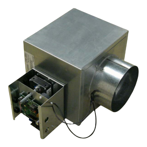
Trane Tracer MP580 Operating instructions

Trane

Trane Tracer MP580 Operating instructions

Trane Picco R3206A User manual

Trane

Trane Picco R3206A User manual

Trane Tracer UC600 Quick setup guide

Trane

Trane Tracer UC600 Quick setup guide

Trane Mini User manual

Trane

Trane Mini User manual

Trane Tracer UC600 Installation and operating instructions
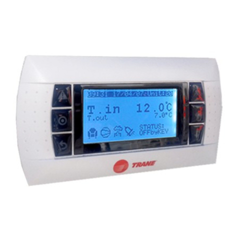
Trane

Trane Tracer UC600 Installation and operating instructions
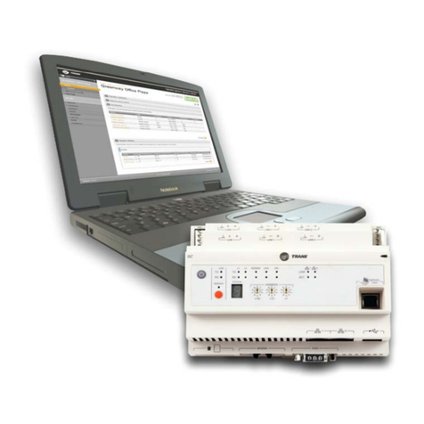
Trane Tracer UC400 Installation and operating instructions

Trane

Trane Tracer UC400 Installation and operating instructions

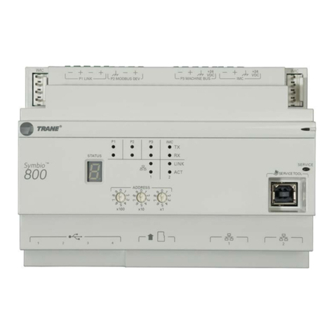
Trane Symbio 800 User manual

Trane

Trane Symbio 800 User manual

Trane Tracer ZN511 Owner's manual

Trane

Trane Tracer ZN511 Owner's manual

Trane Tracer TD7 User manual

Trane

Trane Tracer TD7 User manual

Trane Tracer MP581 Manual

Trane

Trane Tracer MP581 Manual

Trane 700 User manual

Trane

Trane 700 User manual

Trane Tracer AH541 Assembly instructions

Trane

Trane Tracer AH541 Assembly instructions

Trane Tracer MP581 User manual

Trane

Trane Tracer MP581 User manual
Trane 700 User guide

Trane

Trane 700 User guide

Trane PIC Owner's manual

Trane

Trane PIC Owner's manual

Trane Tracer ZN.520 Setup guide

Trane

Trane Tracer ZN.520 Setup guide

Trane Tracer UC600 User manual

Trane

Trane Tracer UC600 User manual

Trane ZN. LonWorks control User manual

Trane

Trane ZN. LonWorks control User manual

Trane Tracer ZN511 User manual

Trane

Trane Tracer ZN511 User manual

Trane Tracer UC210 Owner's manual

Trane

Trane Tracer UC210 Owner's manual

Trane BAYSTAT253A Assembly instructions

Trane

Trane BAYSTAT253A Assembly instructions

Trane Tracer ZN510 Owner's manual

Trane

Trane Tracer ZN510 Owner's manual

Trane Tracer CH535 User manual

Trane

Trane Tracer CH535 User manual

Trane Symbio 210 Installation and operating instructions
Trane

Trane Symbio 210 Installation and operating instructions

Popular Controllers manuals by other brands

Sunricher SR-ZV9003T3-RGBW-US Installation

Sunricher

Sunricher SR-ZV9003T3-RGBW-US Installation

Ksenia intro Installation and configuration manual

Ksenia

Ksenia intro Installation and configuration manual

Inovance CAN200 Series manual

Inovance

Inovance CAN200 Series manual

Gauzy LC6 FLEX Controller Installation and operation guide

Gauzy

Gauzy LC6 FLEX Controller Installation and operation guide

Viking SLP-1 Technical practice

Viking

Viking SLP-1 Technical practice

CKD KBX-30E-U Series instruction manual

CKD

CKD KBX-30E-U Series instruction manual

Sharp Energy Sun Flux User manual & installation guide

Sharp Energy

Sharp Energy Sun Flux User manual & installation guide

Yamaha RCX40 user manual

Yamaha

Yamaha RCX40 user manual

AB Quality PowerFlex 400 Frames D-H Service bulletin

AB Quality

AB Quality PowerFlex 400 Frames D-H Service bulletin

Yamaha MJC8 owner's manual

Yamaha

Yamaha MJC8 owner's manual

AL-KO ATC operating instructions

AL-KO

AL-KO ATC operating instructions

Savant SmartControl 2 Deployment guide

Savant

Savant SmartControl 2 Deployment guide

GameSir T3S user manual

GameSir

GameSir T3S user manual

Kostal inveor operating manual

Kostal

Kostal inveor operating manual

Emerson Yarway 20-55 Operating and safety instructions

Emerson

Emerson Yarway 20-55 Operating and safety instructions

CoCo ACM-LV24 Quick installation guide

CoCo

CoCo ACM-LV24 Quick installation guide

Brooks SLA5810/20 Installation and operation manual

Brooks

Brooks SLA5810/20 Installation and operation manual

SIGMA TEK SR 011 Technical manual

SIGMA TEK

SIGMA TEK SR 011 Technical manual

manuals.online logo
manuals.online logoBrands
  • About & Mission
  • Contact us
  • Privacy Policy
  • Terms and Conditions

Copyright 2025 Manuals.Online. All Rights Reserved.

TAMX Replacement Air Handler Control
Board Conguration
This control board needs congured for use and will not operate
until correctly congured.
INSTALLER'S
GUIDE
IMPORTANT—This Document is customer property and is to remain with this unit. Please return to service information
pack upon completion of work.
ALL phases of this installation must comply with NATIONAL, STATE AND LOCAL CODES
18-GJ92D1-1A-EN
Model:
CNT09289 or
superseded
3. General Information
This replacement control board is used on TAMX air
handlers.
NOTE: This instruction will explain how to configure this
control board to operate.
1. Unpack all components of the kit.
2. Check carefully for any shipping damage. If any
damage is found, this must be reported immediately
and a claim made against the transportation
company.
3. Check to be sure all components are in the
package. Any missing components should be
reported to your supplier at once and replaced with
authorized components only.
Each kit will contain:
Item Qty Description
1 1 Air Handler Control Board
2 1 Installer's Guide
1. Safety Considerations
2. Inspection
IMPORTANT: Follow all Warnings and Cautions in the air
handler Installer's Guide.
THE INFORMATION IN THIS GUIDE IS FOR USE BY
INDIVIDUALS HAVING ADEQUATE ELECTRICAL AND
MECHANICAL BACKGROUND. ANY ATTEMPTS, BY
UNQUALIFIED PERSONS, AT PLUMBING, INSTALLING
OR REPAIRING A HYDRONIC SYSTEM OR CENTRAL
AIR CONDITIONING PRODUCT COULD RESULT IN
PROPERTY DAMAGE, SEVERE PERSONAL INJURY OR
DEATH. THE MANUFACTURER OR SELLER CANNOT
BE RESPONSIBLE FOR THE INTERPRETATION OF THIS
INFORMATION, NOR CAN IT ASSUME ANY LIABILITY IN
CONNECTION WITH ITS USE.
ELECTRICAL HAZARD!
DISCONNECT ALL ELECTRICAL POWER, INCLUDING
REMOTE DISCONNECTS BEFORE INSTALLING OR
SERVICING. FOLLOW PROPER LOCKOUT/TAGOUT
PROCEDURES TO ENSURE THE POWER CAN NOT
BE INADVERTENTLY ENERGIZED. FAILURE TO
FOLLOW THIS WARNING COULD RESULT IN SERIOUS
PERSONAL INJURY, DEATH, OR PROPERTY DAMAGE.
4. Kit Contents
Air Handler Control Board
INSTALLER'S GUIDE
2 18-GJ92D1-1A-EN
5. GET THE APP:
The Diagnostics Mobile App can be found in your device
App Store when searching for Trane Diagnostics or
American Standard Diagnostics. A QR code can be
scanned which sends you directly to the location:
Technician will need Comfortsite or AS Dealernet
credentials to use this tool.
6. Replacement AHC Configuration – 24 volt mode
Replacement AHC boards need programmed and will
not run without configuration IN 24 Volt Mode. There are
2 ways to perform the configuration. 1 of the methods
is required to get the unit running. Combining 2 or more
methods will result in unwanted operation.
1. The most complete configuration will be accomplished
using the Diagnostics Mobile App. In this app, there
are configurations for the model number, blower delays
and accessories.
2. There is a Button Press method to configure the size
of the air handler and is accomplished by pressing
the S1 button on the bottom of the control board in a
sequence explained in this document.
Only 1 of these methods should be used.
After conguration, power cycle the air
handler.
Method #1:
18-GJ92D1-1A-EN 3
INSTALLER'S GUIDE
7. Button Press AHC Configuration Method: Method #2
Replacement AHC will need to be configured for unit size. Airflow will be set at 400 cfm/ton based on unit size configura-
tion. These configurations can be done through the Diagnostics Mobile App with no manual steps or can be done manu-
ally without the Diagnostics Mobile App.
Step Manual Program Unit Model Size Red LED Status
1 Hold J13 BLE button down for 5 seconds and release Red LED will be off
2 Now entering programming 1 Red LED flash alerts user that it is now able to
program
3 If a configuration is present, will announce now Red LED will be off if no configuration is present
4If no configuration is present, AHC will inform you it is
ready to program 5 quick Red LED flashes
5
After 5 quick flashes, start programming within 2 sec-
onds by pressing J13 button. Red LED will also flash
with each button press
1 press= TAMXB0A24
2 press= TAMXB0B30
3 press= TAMXB0C36
4 press= TAMXB0C42
5 press= TAMXB0C48
6 press= TAMXB0C60
62 seconds after the last button press, the Red LED
will flash 1 time to acknowledge programming
Red LED will now flash the number of times you
pressed to confirm your configuration. If you pro-
grammed the wrong size, within 2 seconds, start
step 5 over
7
If the configuration is correct and the BLE button has
not been pressed for 2 seconds, Red LED will an-
nounce successful programming.
After conguration, power cycle the air
handler.
Red LED will turn on for 5 seconds announcing the
configuration has been stored in NV memory cor-
rectly. Red LED will be on for only 2 seconds if not
stored properly. Programming is complete.
8. Replacement AHC Configuration – LINK Communicating Mode:
The System Controller (SC360) will load important parameters in communicating mode and no interaction is necessary
when replacing the AHC. IF the AHC and the System Controller (SC360) need replaced at the same time - contact your
local FSR or technical support agent.
Table 1: Conguration for Replacement AHC
About Trane and American Standard Heating and Air Conditioning
Trane and American Standard create comfortable, energy efficient indoor environments for residential applications.
For more information, please visit www.trane.com or www.americanstandardair.com
The manufacturer has a policy of continuous data improvement and it reserves the right to change design and specifications without
notice. We are committed to using environmentally conscious print practices.
© 2022
18-GJ92D1-1A-EN 21 Oct 2022
Supersedes (New)