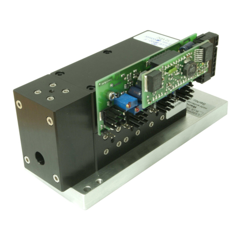
Traxon e:cue Genius AM38213003I Specification sheet


This manual suits for next models
1
Table of contents
Other Traxon Lighting Equipment manuals
Traxon
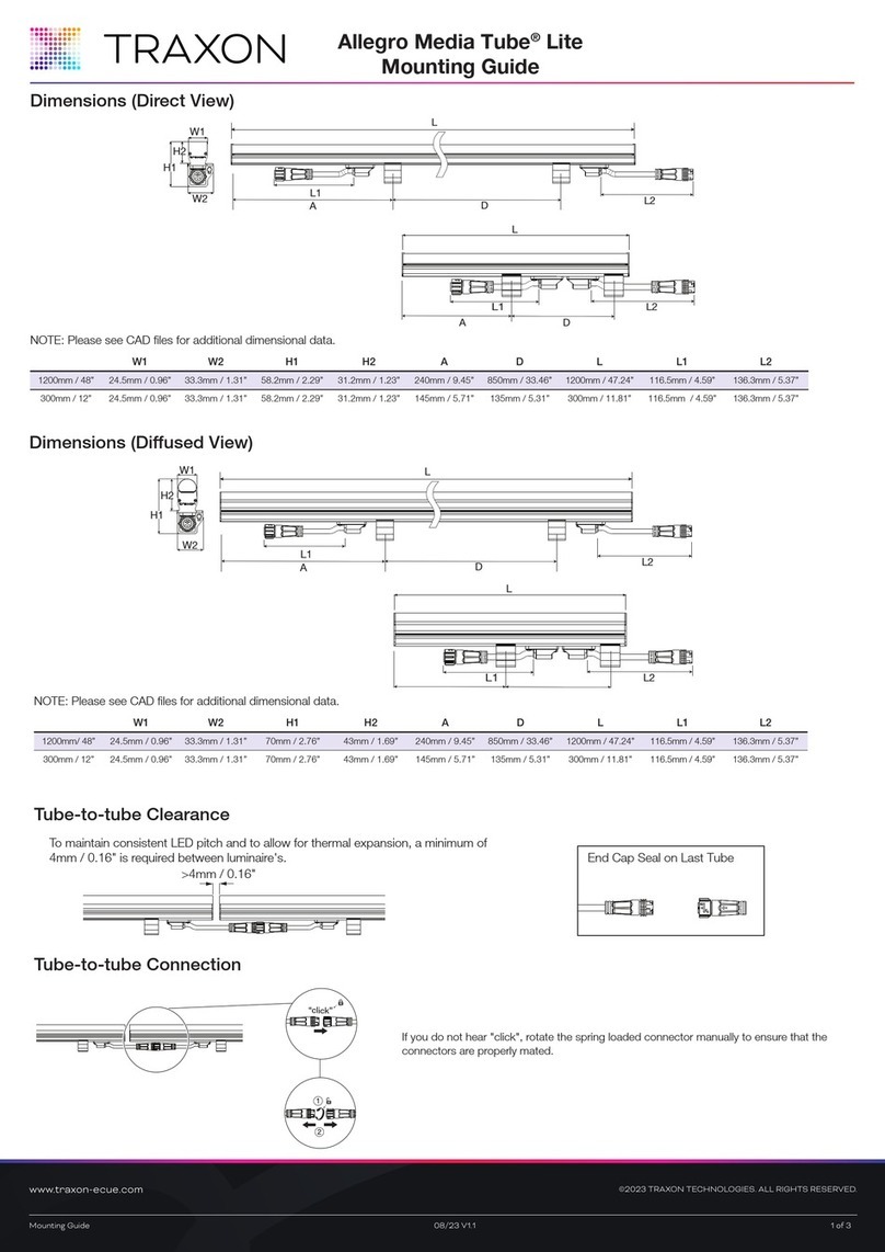
Traxon Allegro Media Tube Lite Installation instructions manual
Traxon
Traxon Media Tube HO User manual
Traxon
Traxon ARCHISHAPE Dot 2.0 S CE User manual
Traxon
Traxon Pro Washer Pro Nano User manual
Traxon
Traxon Osram Media Tube Go User manual

Traxon
Traxon ProPoint Vista 100W User manual

Traxon
Traxon e:cue SYMPL pro Node User manual
Traxon
Traxon Allegro Dot S Direct View User manual

Traxon
Traxon ARCHISHAPE Tube Ultra Slim User manual
Traxon
Traxon RGB 50 144PXL User manual

Traxon
Traxon Allegro Dot S Direct View User manual
Traxon
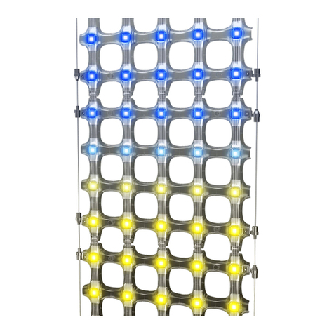
Traxon Mesh Installation instructions manual

Traxon
Traxon Allegro Dot M/L Direct View User manual

Traxon
Traxon ProPoint Vista Series User manual

Traxon
Traxon Allegro Media Tube Lite User manual

Traxon
Traxon Washer Quattro AC XB Installation instructions manual

Traxon
Traxon Media Tube HO Installation instructions manual
Traxon
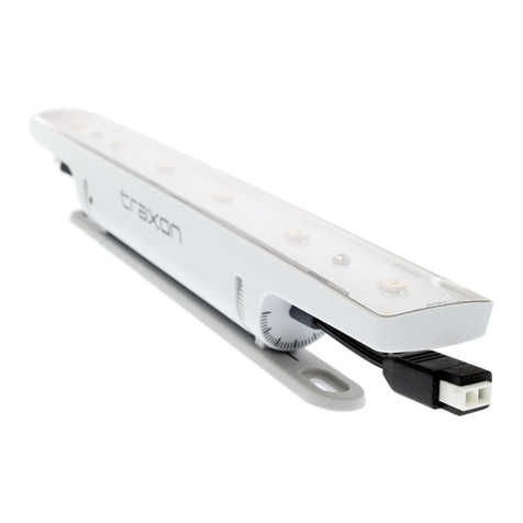
Traxon Cove Light AC DIM Installation instructions manual
Traxon
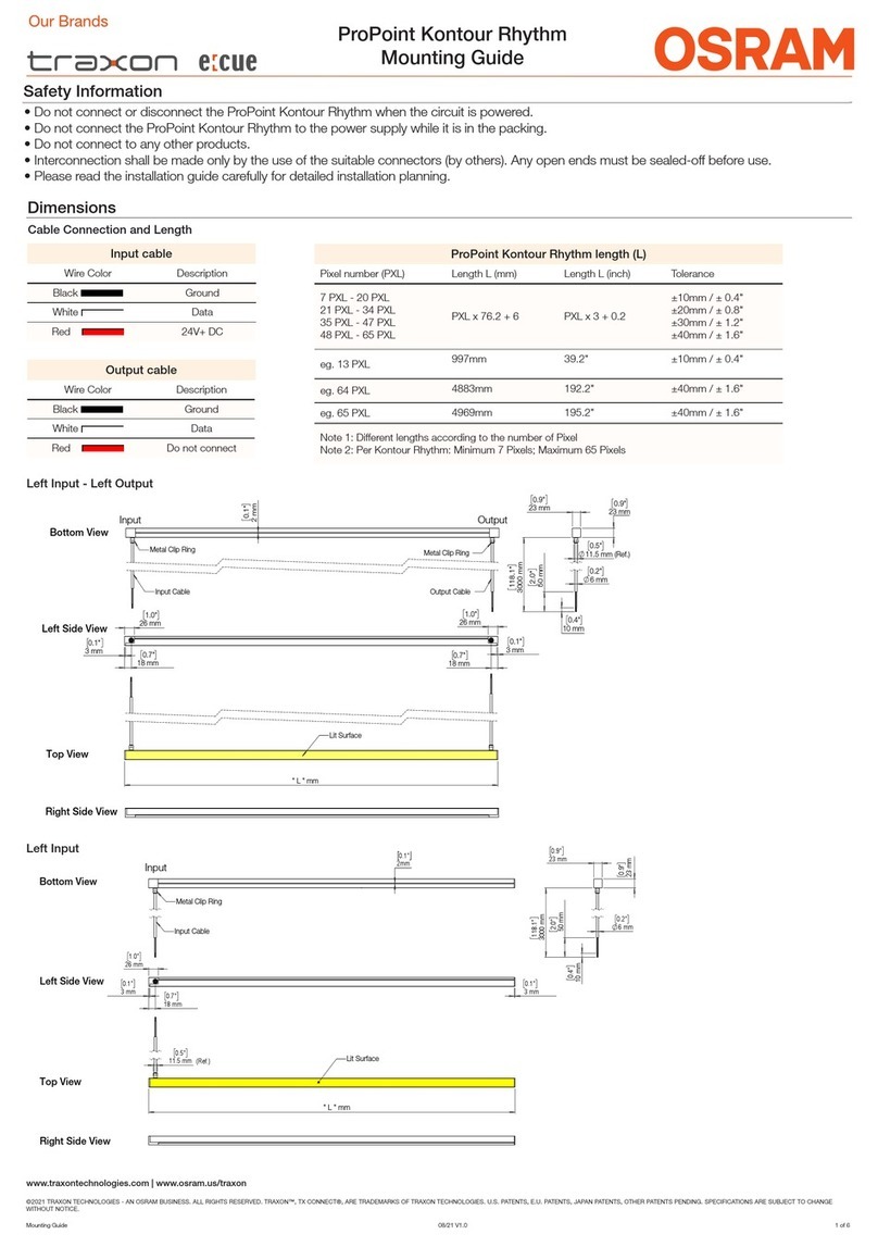
Traxon e cue Osram ProPoint KR.MA.01.10001 Installation instructions manual
Traxon
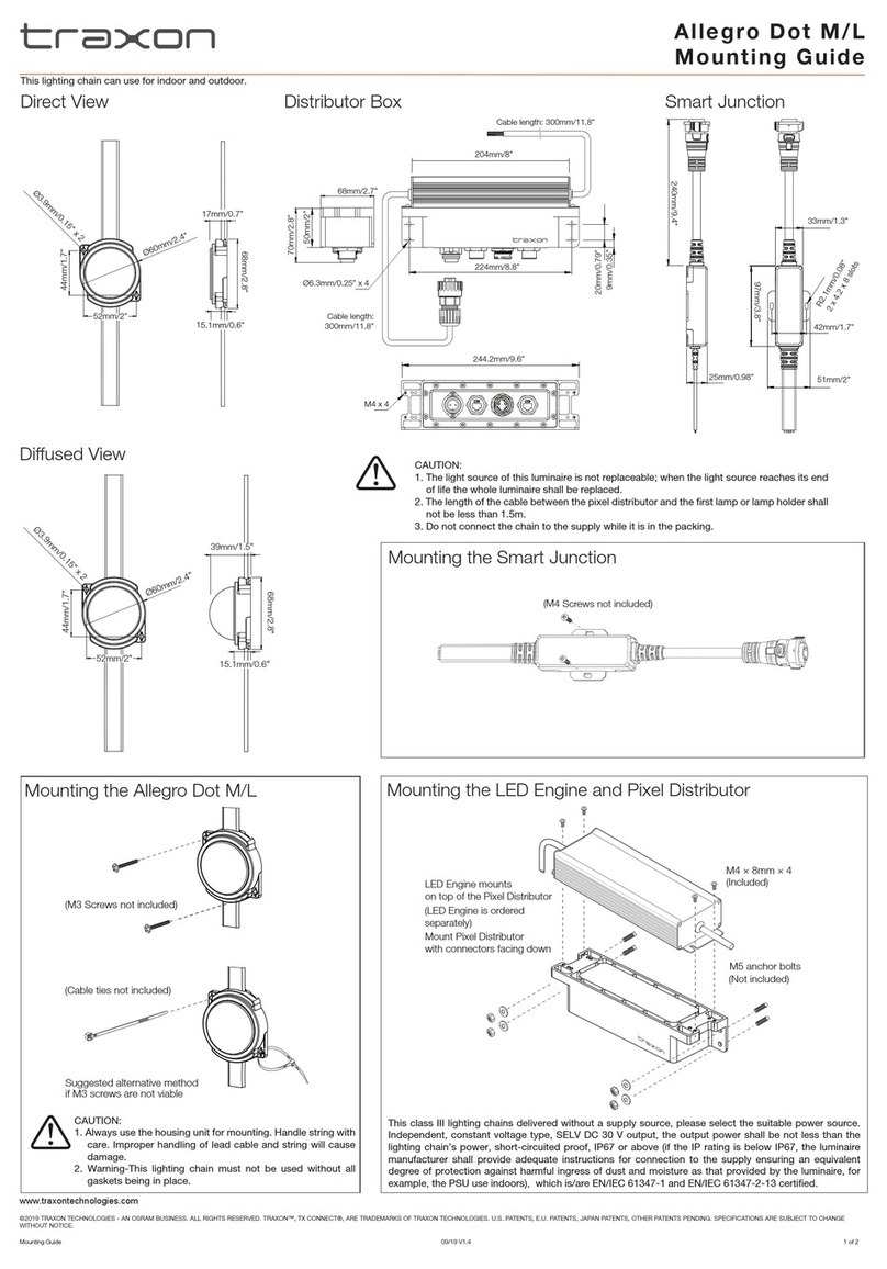
Traxon Allegro Dot M Installation instructions manual
Popular Lighting Equipment manuals by other brands

Martin
Martin Mania EF3 user manual

RAB
RAB STL200H/L instructions
Chauvet
Chauvet Vue 6.1 user manual
Chauvet Professional
Chauvet Professional REMRB50CMIPCURVE user manual

LITESHEET
LITESHEET BriteCor AC BDEK installation manual

North American Signal
North American Signal LED Traffic Assist III Series Installation and operating instructions
