Trek INCITE 6i User manual

CONTENTS
Safety and general guidelines
...............................
i
Functions
..............................................................
1
Installation
........................................................
2-3
Setting the computer
........................................
4-7
6i, 8i
...............................................................
.
4-5
9i, 11i
..............................................................
6-7
Changing functions and other normal use
..........
8
Replacing the battery
...........................................
8
Troubleshooting and Warranty
............................
9
SAFETY AND GENERAL GUIDELINES
While riding your bicycle, do not stare at the computer for long
periods of time (Figure 1). If you do not watch the road, you
could hit an obstacle, which may cause you to lose control and
fall.
Make sure the computer wire cannot contact the tire or wheel
spokes. The wire could be damaged causing the computer to
malfunction. Also, the wire could get caught, causing you to
lose control and fall.
TREK INCITE
Bicycle Computer Owner’s Manual
This manual explains the installation and use of several Trek bicycle computer models:
• Incite 6i
Incite 8i
• Incite 9i
Incite 11i
Please read this manual carefully and save it for future reference.
If you do not understand the information in this manual, or you have a question about your Incite
computer that this manual does not cover, consult your Trek dealer. If you have a question or problem
that your Trek dealer can’t handle, contact us at:
Trek Bicycle Corporation
Attn: Customer Service
801 W. Madison Street
Waterloo, Wisconsin 53594
http://www. trekbikes.com (920) 478-4670
© Copyright Trek Bicycle Corporation
2004 All rights reserved
Figure 1- Watch the road
when riding.
Figure 2- Keep the wire
out of the spokes

1
FUNCTIONS
Not all Trek Incite computer models have all these functions.
Table 1- Function abbreviations, names and explanations
Function
Explanation
Speed
Current speed of the bicycle displayed in miles per hour (MPH) or kilometers per hour (KPH). Highest readings:
• 6i, 8i: 107.3mph or 172.7kph
• 9i, 11i: 80.5mph or 129.6kph
CLK
Clock
Time of day displayed in hours and minutes, in 12-hour or 24-hour format
TME
Time
Amount of time elapsed since last reset. Displayed in hours, minutes, and seconds. Highest readings:
• 6i, 8i: 9:59:59
• 9i, 11i: 23:59:59
MAX
Maximum speed
Highest speed since last Reset displayed to tenths. Highest readings:
• 6i, 8i: 107.3mph or 172.7kph
• 9i, 11i: 80.5mph or 129.6kph
TRP
Trip distance
Amount of distance elapsed since last Reset displayed in miles or kilometers, and tenths. Highest reading:
• 999.9
ODO
Odometer
Amount of distance elapsed since installation or programming displayed in miles or kilometers. Highest reading:
• 99,999
AVG
Average speed
Average speed since last Reset displayed to tenths. Highest readings:
• 6i, 8i: 99.9mph or 172.7kph
• 9i, 11i: 80.5mph or 129.6kph
CAD
Cadence
Number of revolutions per minute of the crankset displayed in whole number. Maximum 240.
Temperature
Current temperature displayed in Fahrenheit or Celsius in whole numbers, updated every 30 seconds. Range:
• -2 to 140°F +/-2°
• -19 to 60°C +/-1°
Pacer
Indication whether current speed is above or below average speed displayed by arrow pointing up (above) or down
(below).
Wheel select
Second wheel size calculation, indicated by circle or circle within a partial second circle.
Functions
2
INSTALLATION
Tools needed:
• Electrical tape
• Slot-type screwdriver
• Phillips-type screwdriver
• Scissors
This section explains the steps to install your computer onto your bicycle:
• Placing the computer on the handlebar
• Placing the magnet and sensor(s) on the bike
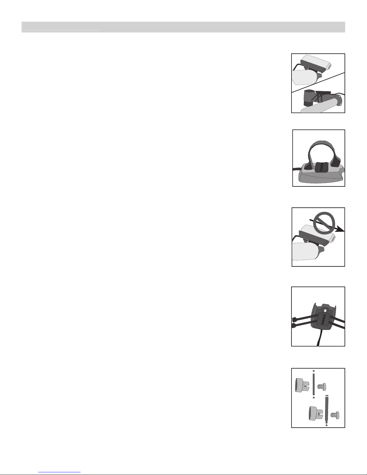
Placing the computer on the handlebar
The Trek Incite computer can be mounted on the handlebar or on the stem (Figure
3).
To install the computer on the handlebar
1. Determine your bicycle’s handlebar diameter: 22.2mm, 25.4/26.0mm, or 31.8mm.
2. Select the corresponding bar clamp
For a 22.2mm bar, use the rubber shim (provided) inside the smaller clamp.
3. Insert the handlebar clamp into the back of the computer base (Figure 4) and
slide it towards the front of the base.
4. Insert the rubber friction pad into the computer base, aligned across the
computer base.
5. With the wire pointing toward the front of the bike, wrap the bar clamp around
the handlebar.
6. Insert the screw through the washer and into the computer base.
7. Tighten the screw until the computer base cannot rotate on the handlebar.
8. Slide the computer into the computer base until the front of the computer and
computer base line up.
9. Check that the computer base cannot be rotated around the handlebar, and that
the computer cannot slide backwards on the computer base (Figure 5).
To install the computer on the stem
1. Insert the rubber friction pad into the computer base, aligned along the
computer base.
2. Insert two nylon ties through the computer base (Figure 6).
3. Place the base on the stem and tighten the nylon tie.
4. Slide the computer into the computer base until the front of the computer and
computer base line up.
5. Check that the computer base cannot be rotated around the stem and the
computer cannot slide backwards on the computer base.
6. Tighten the nylon ties and trim the excess length.
Placing the magnet and sensor(s) on the bike
The wheel magnet must be aligned so that it passes across the sensor. As the
magnet passes the sensor, it must be no further from the sensor than 1 to 3mm (1/
32 to 1/8 inch).
The wheel magnet has a ‘T’ shaped slot with two configurations: round spokes and
flat or bladed spokes (Figure 7).
Computers with the cadence function have two sensors. The shorter computer
wire is for the cadence sensor which mounts near the crankset. The sensor must be
aligned so that the magnet passes within 1-3mm of the sensor, and in line with
the small line on the sensor (Figure 8).
To install the magnet
1. Remove the screw from the magnet.
2. Slide the slot in the back of the magnet over the spoke.
For a flat or bladed spoke, start the spoke near the end where the spoke is round, and align the
top of the ʻTʼ with the spoke as you slide the magnet up the blade.
3. Thread the screw into the magnet until it is snug against the spoke.
Installation
Figure 6- Nylon tie
threaded through com-
puter base
Figure 7- Magnet placed
on round and oval
spokes
Figure 3- Computer on
handlebar and stem
Figure 4- Clamp and
friction pad in computer
base
Figure 5- Make sure the
computer cannot be
bounced off.

3
Attaching the computer wire
The computer wire is usually longer than needed. Extra wire length can be
diverted by wrapping it around the brake housing prior to routing it down the fork
blade or down tube (Figure 9).
Make sure the computer wire is not pulled tight when the handlebar is turned all
the way to either side.
Wireless computers do not have wires. For wireless computers, see
To install the
sensor.
To attach the computer wire
1. Determine the length of wire to divert by holding the sensor at its desired
mounting point.
2. Wrap the wire around the front brake cable, diverting the determined amount.
3. Continue routing the wire, either by wrapping around the fork or frame tube, or
attach the wire to the fork or frame tube with electrical tape.
4. As needed, solidify the wire attachment with either nylon ties or electrical tape.
To install the sensor
These instructions are written for the front wheel, but apply equally to installing
the magnet and cadence sensor which go on the left crank and the frame’s
chainstay.
1. Align the sensor with the magnet.
The magnet must pass across the line on the sensor (Figure 10).
2. Orient the sensor so that the clearance between the sensor and the magnet is
between 1 to 3mm.
The sensor can be rotated around the fork blade or crank about 45 degrees.
If needed, the sensor and magnet can be moved up or down the fork and wheel to change the
clearance.
3. For the wireless sensor, install the rubber “foot” in the sensor (Figure 11).
4. Attach the sensor with nylon ties, but do not fully tighten.
5. With the computer in the computer base, check the alignment of the sensor and
magnet by spinning the wheel and noting if the computer is displaying speed.
If the computer shows current speed, the sensor is reading the magnet. If the computer is not
displaying current speed, realign the sensor and magnet until current speed is displayed.
6. Tighten the nylon ties and trim the excess length (Figure 12).
Installation
Figure 12- Trim excess
nylon tie length
Figure 11- Wireless sen-
sor, foot, and fork blade
Figure 8- Magnet placed
on crankarm, aligned
with sensor on chainstay
Figure 9- Extra wire
wrapped around the
brake housing
Figure 10- Magnet align-
ment and clearance
1.0 -
3.0mm
3.0mm
3.0mm

4
SETTING THE COMPUTER
The computer must be set, or “programmed,” so that it gives its readout in the units preferred by the
user, and so that it calculates with the correct wheel size. There are three ways to use the buttons:
• Push- touch once
• Cycle- push repeatedly as needed
• Hold- push and hold in for two or three seconds
The method used to set the computer varies according to the computer model. Follow the instruc-
tions covering your computer model, grouped as follows:
• Incite 6i and 8i (pages 7-9)
• Incite 9i and 11i (pages 10-12)
INCITE 6I AND 8I
Setting the 6i and 8i is done by pushing the two buttons in a specific sequence. The button on the
side of the computer is the
Set
button. The large button on the bottom, which may look like two
buttons, is the
Mode
button.
To set Odometer and Wheel size
By default, the odometer always starts at ‘0’. If desired, the odometer can be manually set at another
value.
1. Cycle
Mode
to ODO.
2. Hold
Mode
until MH flashes.
3. Cycle
Set
between MH and KMH.
4. Push
Mode
to select measurement conversion.
5. Cycle
Set
to the preferred wheel size.
For a custom wheel size, see
To set a custom wheel size
6. Push
Mode
to select wheel size.
7. Cycle
Set
for the first digit of Odometer.
8. Push
Mode
to select the digit.
9. Repeat steps 7 and 8 to select the other digits of Odometer.
The computer returns to current speed.
To set Custom wheel size
1. Cycle
Mode
to ODO.
2. Hold
Mode
until MH flashes.
3. Cycle
Set
between MH and KMH.
4. Push
Mode
to select measurement conversion.
5. Cycle
Set
to the four-digit number (see Table 2).
Table 2- Wheel size and corresponding settings in millimeters
700 x 20
2086
26 x 1.5
2010
700 x 23
2096
26 x 1.90
2045
700 x 25
2105
26 x 1.95
2050
700 x 28
2136
26 x 2.0
2055
700 x 32
2155
26 x 2.1
2068
700 x 35
2168
26 x 2.2
2075
700 x 38
2180
Custom
0000 - 2999
6. Hold
Set
until the last digit flashes.
7. Cycle
Set
to your preferred value for the digit.
8. Push
Mode
to select.
9. Repeat steps 7 and 8 to select the other three digits.
10. Push
Mode
.
10. Cycle
Set
for the first digit of Odometer.
11. Push
Mode
to select the digit.
12. Repeat steps 10 and 11 to select the other digits of Odometer.
The computer returns to current speed display.
Setting the computer
Other manuals for INCITE 6i
2
Table of contents
Other Trek Bicycle Accessories manuals

Trek
Trek Bicycle Computer User manual

Trek
Trek Pro RT User manual

Trek
Trek INCITE 11i User manual

Trek
Trek CarBack User manual

Trek
Trek INCITE 6i User manual

Trek
Trek Fusion C User manual

Trek
Trek 08 User manual

Trek
Trek Sonic 2.0 User manual

Trek
Trek TQ Drive System User manual

Trek
Trek INCITE 6i User manual


Popular Bicycle Accessories manuals by other brands


Specialized
Specialized Elite CylcoComputer user manual

Sigma
Sigma BC 16.16 manual

Playcore
Playcore Dero Setbacks installation instructions

VDO Cyclecomputing
VDO Cyclecomputing x3dw instruction manual

Cateye
Cateye RAPID X2 manual

buratti meccanica
buratti meccanica Clorofilla Trail Use and maintenance manual


