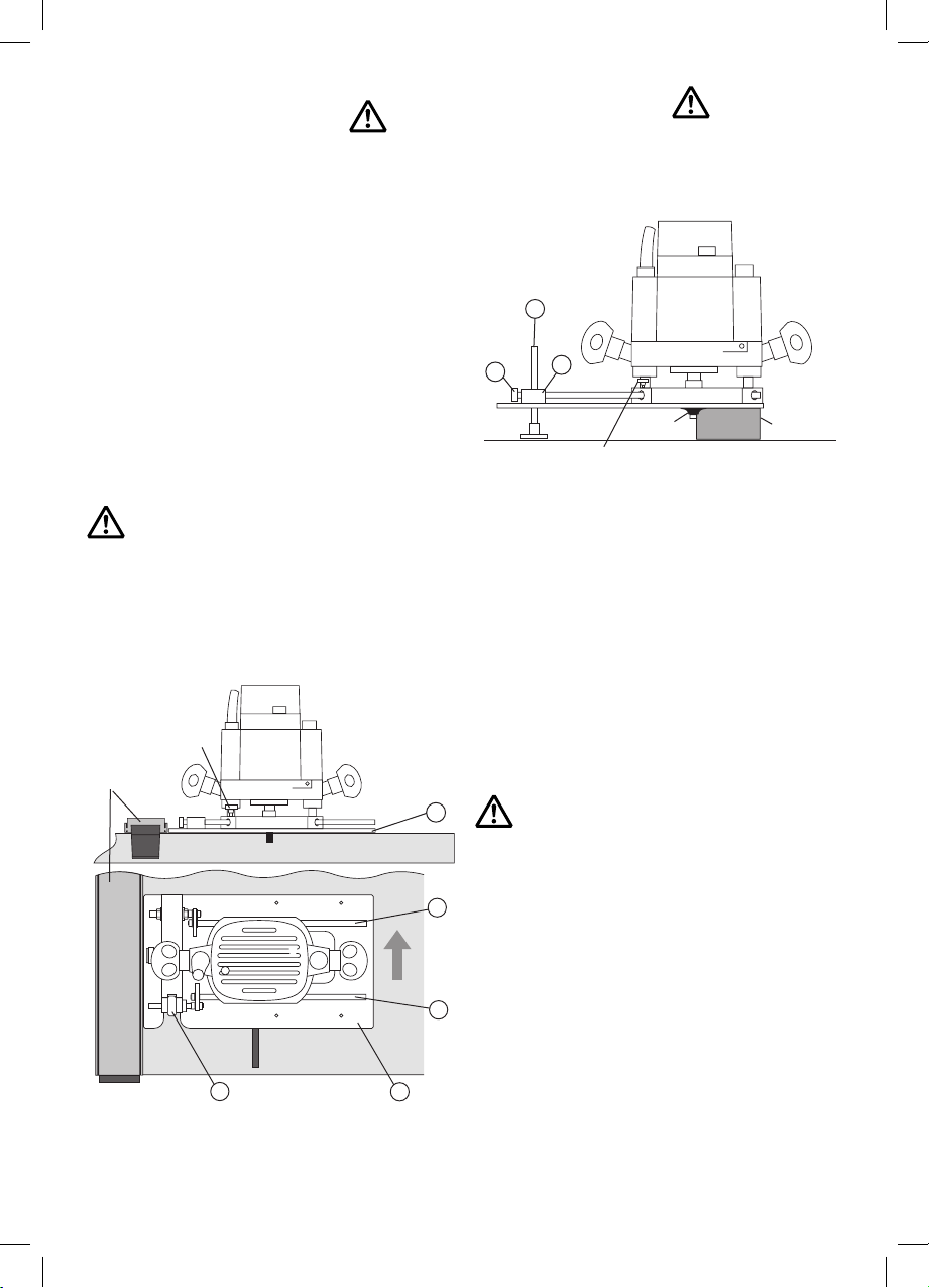
Set the depth of the cutter as usual and rest the router on the
work piece as if to start a routing pass. Release the bridge
pinch-bolt so the anti-tilt leg drops down and the foot rests
on the bench top. Without moving the router or anti-tilt leg
retighten the bridge pinch-bolt locking the anti-tilt leg at the
height which will then support the previously unsupported side
of the router.
Before completing the routing pass check that
the bench surrounding the work piece is smooth
and even. Complete a couple of dry runs with the
router around the work piece ensuring that the
anti-tilt leg has a clear path and the router remains
stable whilst the pass is completed.
4. Anti-tilt Support
The CRB’s anti-tilt leg is designed specifically to aid stability
when routing narrow sections of material. The leg is in two
parts so its height if necessary can be reduced by unscrewing
the rods.
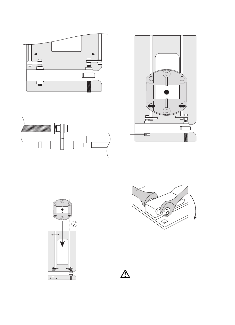
Slide the anti-tilt leg into the bridge pinch-bolt hole from the
underside of the baseplate. Lock it in position with the plastic
foot up against the underside of the baseplate. Slide the router
onto the CRB’s rods and lock the router in position using the
router fence rod knobs. Ensure that the router is positioned
to allow the router cutter to sit safely within the baseplate
‘letterbox’.
Maximum height = 80mm (3 1/8”)
Minimum height = 8mm (5/16”)
Component
8
41
Cutter
Router fence knob
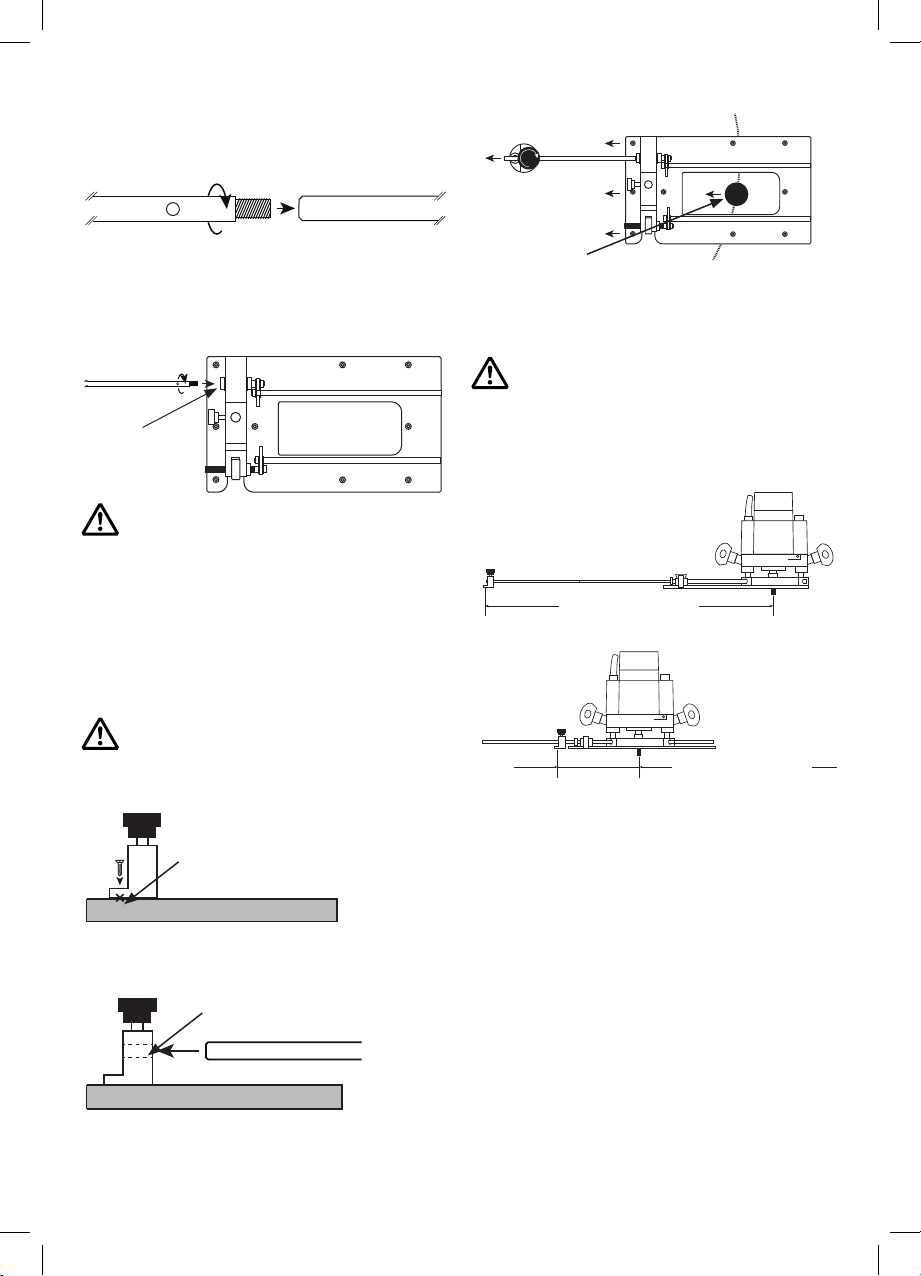
3. Using the CRB with a
Clamp Guide
Using a clamp guide and router to groove across the width
of a work piece is a useful and common practice. However
considerable time is taken to accurately set the clamp guide at
right angles to the edge of the board simultaneously ensuring
a precise distance from the desired position of the rebate.
The CRB’s micro adjuster removes the need to set the
distance between clamp guide and groove.
Ensure the clamp guide is set at right angles to the board
edge and within the range of the routers movement on the
CRB’s rods. Slide the router to the approximate position of the
required rebate and using the router fence rod knob on the
router base lock the router onto the CRB’s adjuster rod.
Plunge the cutter to the work piece surface (with the router
turned off) and using the micro adjuster bring the edge of the
cutter up to the line denoting the location of the rebate. Run
the bridge end of the CRB’s baseplate up against the clamp
guide and using an even pressure ensure the router moves
smoothly down the length of the clamp guide.
If a deep rebate or groove is needed several lighter
cutting passes may result in a better finish.
If two grooves are needed within 110mm centre to centre of
each other, (using a 1/4” cutter) they can be routed without
moving the clamp guide by simply sliding the router down the
CRB’s rods to the next location.
2
6B
5B
2
4
Clamp
guide
Router fence
rod knob
-9-