Graco Spindl-Gard 24B219 User manual

Instructions
High Speed Spindl-Gard™
Lubrication System with
Electric Pump 313444E
EN
For applying a constant quantity of oil directly to rotating bearing elements that operate at
speeds greater than 250,000 DN. For professional use only.
Models: Page 2
320 psi (2.2 MPa, 22 bar) Maximum Working Pressure
Components:
•Electric motor driven pump
•0.8 gallon (3 liter) plastic reservoir
•Air/oil dispensing module
•Optional programmable timer/controller
Important Safety Instructions
Read all warnings and instructions in this
manual before using the equipment. Save
these instructions.

Spindl-Gard with Electric Pump Models
2313444E
Spindl-Gard with Electric Pump Models
Model
No.
Controller
Option Voltage Number of Outlets
Outputs from Inlet to
End CC/Stroke
(cu in./stroke)
Remote
(no timer)
Timer Included
(AC Models Only
24 VDC
115 VAC
230 VAC
12345678
Plugged
0.025 (0.0015)
0.049 (0.0030)
0.082 (0.0050)
24B219 XX X X
24H681 XX X X
24R127 XX X X
24V204 XX X X
24V531 XX X X
258295 XX X X X
258301 XX X X
258347 XX X XX
25A202 XXX X
25A209 XX X X
564445 XX X X
25C264 XX X X
25C265 XXXX X
26C419 XX X X
26C521 XX XX

Warnings
313444E 3
Warnings
The following warnings are for the setup, use, grounding, maintenance, and repair of this equipment. The exclama-
tion point symbol alerts you to a general warning and the hazard symbols refer to procedure-specific risks. When
these symbols appear in the body of this manual, refer back to these Warnings. Product-specific hazard symbols and
warnings not covered in this section may appear throughout the body of this manual where applicable.
WARNING
EQUIPMENT MISUSE HAZARD
Misuse can cause death or serious injury.
• Do not operate the unit when fatigued or under the influence of drugs or alcohol.
• Do not exceed the maximum working pressure or temperature rating of the lowest rated system
component. See Technical Specifications in all equipment manuals.
• Use fluids and solvents that are compatible with equipment wetted parts. See Technical
Specifications in all equipment manuals. Read fluid and solvent manufacturer’s warnings. For
complete information about your material, request MSDS forms from distributor or retailer.
• Check equipment daily. Repair or replace worn or damaged parts immediately with genuine
manufacturer’s replacement parts only.
• Do not alter or modify equipment.
• Use equipment only for its intended purpose. Call your distributor for information.
• Route hoses and cables away from traffic areas, sharp edges, moving parts, and hot surfaces.
• Do not kink or over bend hoses or use hoses to pull equipment.
• Keep children and animals away from work area.
• Comply with all applicable safety regulations.
ELECTRIC SHOCK HAZARD
Improper grounding, setup, or usage of the system can cause electric shock.
• Turn off and disconnect power at main switch before disconnecting any cables and before servicing
equipment.
• Connect only to grounded power source.
• All electrical wiring must be done by a qualified electrician and comply with all local codes and
regulations.
PRESSURIZED EQUIPMENT HAZARD
Fluid from the gun/dispense valve, leaks, or ruptured components can splash in the eyes or on skin and
cause serious injury.
• Follow Pressure Relief Procedure in this manual, when you stop spraying and before cleaning,
checking, or servicing equipment.
• Tighten all fluid connections before operating the equipment.
• Check hoses, tubes, and couplings daily. Replace worn or damaged parts immediately.

Component Identification
4313444E
Component Identification
NOTE: Reference letters are used throughout the instructions on the following pages. Refer back to this page as
needed.
A Purge Plug
B Manual Run Reset Button
C Pump ON LED
D Power ON LED
E Alarm LED
F 1/4-18 Air Regulator Inlet, NSPF
G Air/Oil Delivery Line
H AIr Flow Adjustment Screw
J Oil Pressure Gauge
K Air/Oil Mixing Block
A
BCDE
J
F
H
GK

Installation
313444E 5
Installation
NOTE: Reference letters used throughout these instruc-
tions refer to the reference letter provided on the Com-
ponent Identification page 4.
• Mount panel in a dry location near the bearing that
is being serviced.
• Line length from the air/oil mixing blocks (K) to the
spindle ranges from 2 to 50 feet (0.61 m to 15.24
m).
• Mount panel using 3/8 inch (0.375 mm) diameter
bolts. Panel mounting dimensions are provided in
the Technical Data section of this manual, page 13.
Grounding
The equipment must be grounded. Grounding reduces
the risk of static and electric shock by providing an
escape wire for the electrical current due to static build
up or in the event of a short circuit.
Electrical Connections - All
Models
1. Verify all power to the system is disconnected.
2. Remove enclosure cover from top of pump.
3. Install electrical cable through connector located on
right side of electrical enclosure.
4. Referring to the wiring diagram for your model (115
and 230 VAC or 24 VDC) in FIG. 1, connect Pump
Power leads to their respective terminals within the
enclosure.
FIG. 1
Wiring Diagram: 115 VAC & 230 VAC Units
Wiring Diagram: 24 VDC Units

Installation
6313444E
Timer Models Only
5. Connect input power leads to the input terminal
block (Terminals 4 and 6) (FIG. 2).
All Models
6. Replace electrical enclosure cover.
Pneumatic Connections
Pressure Relief Procedure
1. Loosen the purge plug (A) on the air/oil mixing block
assembly (K).
2. Press the manual run button (B) until oil flows out of
the port.
Connecting Pneumatic Fittings - All models
NOTE:
• Incoming air should be dry (40°F, 4.4°C) and be fil-
tered to 5 micron.
• Minimum inside diameter of incoming air line should
be 0.25 inch (0.63 cm).
1. Connect incoming air line to the 1/4-18 NPSF inlet
(F).
2. Connect air/oil delivery line from the air/oil mixing
block (K) to the bearing point.
Air Flow Data Chart
The tube size from the air/oil mixing block (K) to the bearing is critical for proper air and oil delivery to the bearings.
Refer to the Air Flow Chart (below) for orifice and corresponding delivery tube sizes and the resulting airflow.
FIG. 2
Orifice Size
Inches (mm)
Delivery Tube
O.D.
Inches (mm)
Delivery Tube
I.D.
Inches (mm)
Air Flow @30 psi
SCFM (LPM)
Air Flow @ 60 psi
SCFM (LMP)
0.030 (0.76) 3/16 (5) 1/8 (3) 16.1 (0.570) 25.2 (0.890)
0.040 (1.00) 1/4 (6) 3/16 (5) 27.7 (0.980) 45.2 (1.600)
0.050 (1.27) 5/16 (7) 1/4 (6) 48.4 (1.710) 81.5 (2.880)
0.060 (1.52) 5/16 (7) 1/4 (6) 103.7 (2.180) 103.9 (3.670)

Installation
313444E 7
Setup
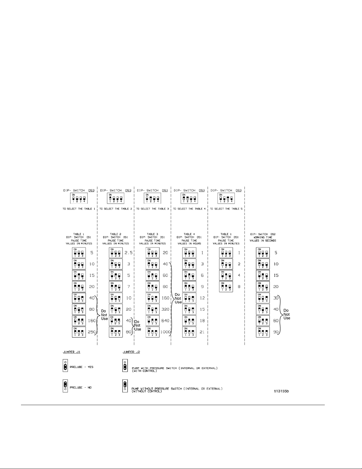
1. Set the desired Pause (off) and Work (on) Times for
your model using the 3 banks of dip switches (DS-1,
DS-2, DS-3) located under the electrical enclosure
cover on the top of the pump. (See Dip Switch Set-
tings, page 8.)
The possible time choices for both the Pause and
Work Times are shown on page 8.
NOTE:
• Pause (off) Time cannot exceed 20 minutes.
• Work (on) Time cannot exceed 20 seconds.
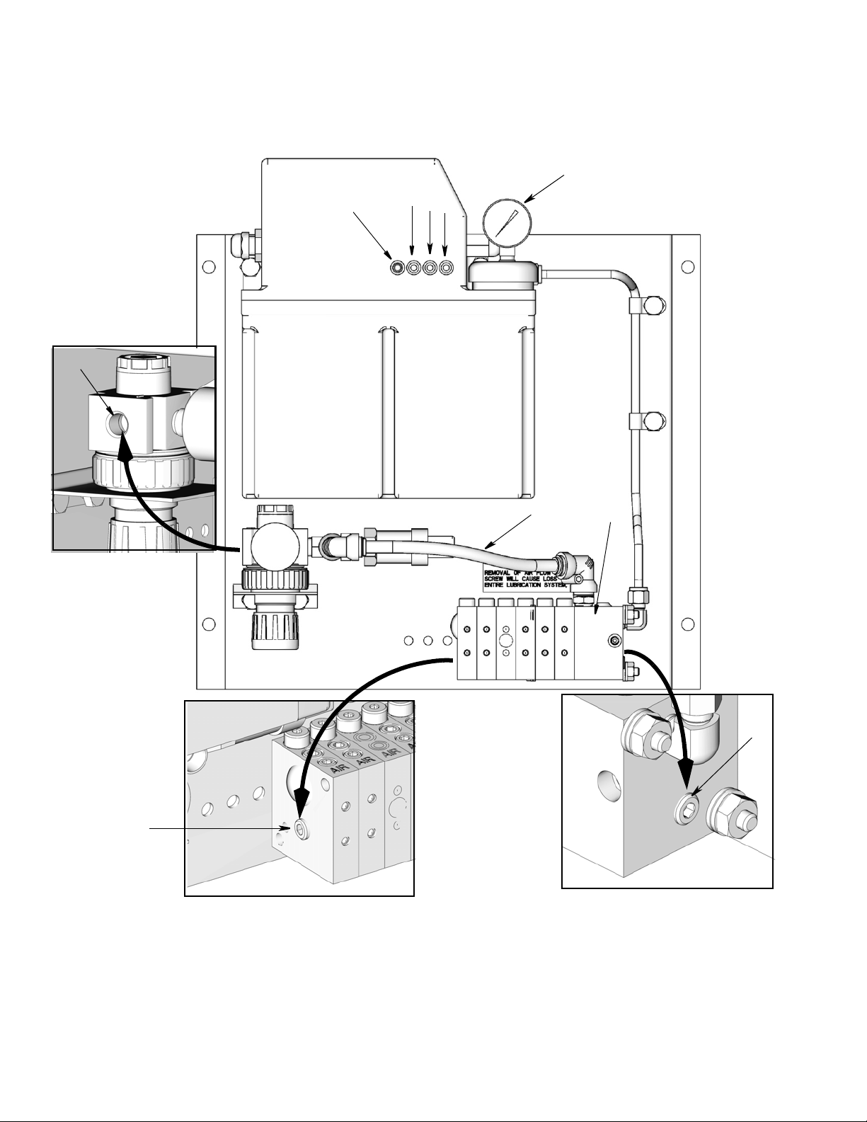
2. Adjust the air flow using the air flow adjustment
screw (H) located on the air/oil mixing blocks (K) by
turning the set screw counter-clockwise. When the
screw is flush with the surface of the block, the
blocks are full open.
To restrict the air flow, turn the adjustment screw
clockwise.
NOTE: Entirely removing the air flow adjustment
screw (H) will cause a loss of air pressure to the
entire lubrication system.
3. Set the pressure regulator for the air/oil mixing
blocks between 30 and 60 psi (0.20 MPa, 2.06 bar
and 0.41 MPa, 4.13 bar). Refer to Air Flow Chart,
page 6 for setting guidelines.
4. Air flow is supplied on a constant basis to the air-oil
mixing block. Adjust the air regulator to achieve the
required air pressure as follows.
a. Fill the reservoir with spindle oil.
b. Press the manual run button (B).
c. Loosen the purge plug (A) on the air/oil mixing
block assembly (K).
d. Press the manual run button (B) until oil flows
out of the port. As oil begins flowing out of the
purge port, quickly tighten the purge plug (A).
e. Press the manual run button (B) 10 additional
times (allowing approximately 5 seconds OFF
time). The pressure should build on the oil pres-
sure gauge (J) to 320 psi (2.21 MPa, 22.1 bar)
and drop to 0.0 psi (0 MPa, 0 bar).
f. If pressure is not established, repeat steps b - e.
Adding a Lubrication Point
To add a point, the air/oil mixing assembly must be
removed from the panel. An additional mixing module
and new tie rod combination can then be added.
Plugging a Lubrication Point
To plug an air/oil outlet, Graco Plug Part No. 555456
must be installed in the piston distributor port on top of
the air/oil mixing block.

Installation
8313444E
Dip Switch Settings: Models With Timers
Pause (off) Time (FIG. 2 and FIG. 3)
The Pause (off) Time is set using dip switches DS3 and
DS1 to select the time to deliver the required lube vol-
ume per hour. For example: If 12 cycles per hour are
required 60 ÷ 12 = 5; set the pause time to 5 minutes.
NOTE: Do not exceed 20 minutes Pause (off) time.
Work (on) Time (FIG. 2 and FIG. 3)
The Work (on) Time is set using the DS2 dipswitches.
NOTE: A Work (on) Time of 20 seconds will normally be
sufficient.
Prelube (FIG. 2 and FIG. 3)
J1 is used to Yes or No. When set to Yes, the lube cycle
will immediately power up.
Pressure Switch (FIG. 2 and FIG. 3)
For timer models, J2 must be set to the monitored posi-
tion.
FIG. 3

Installation
313444E 9
Controller Settings: Models With Timers
Pause (off) Time (FIG. 3)
Set the Pause (off) Time to between 2 minutes and 20
minutes to deliver the required lube volume per hour.
NOTE: Do not exceed 20 minutes Pause (off) time.
Monitor Time (FIG. 3)
Set the Monitor Time to 20 seconds. This will allow suffi-
cient time for the system pressure to rise, piston distrib-
utors to fire and the oil pressure switch to close.
Cycle Switch (FIG. 3)
Set Cycle Switch (oil pressure switch) transition to 1.
Pressure Switch (FIG. 3)
For timer models, J2 must be set to the monitored posi-
tion.

Operation
10 313444E
Operation
Theory of Operation
Air is constantly being applied to the air/oil blocks. After
a preset Pause (off) Time, the controller activates the
pump. The green “Power ON” LED (D) lights. System
pressure builds causing the piston distributors within the
air/oil mixing module to fire. The “No OIL” pressure
switch closes.
The output from the piston distributor is discharged to
the air/oil mixing chamber where the constant flow of air
causes a thin film of oil to flow along the delivery tube in
a constant, wave-like motion. This film is then applied in
the form of a very fine spray from a drilled orifice or noz-
zle tube to the bearing elements on a constant basis.
If the oil pressure switch closes before the expiration of
set Work Time, the pump and “Pump ON” LED (C) turns
off and the timer begins its count down to the next lube
occurrence.
If the oil pressure switch does NOT close before the
expiration of the set Work Time, a fault is registered,
causing a red “Alarm” LED (E) to light. The Fault Alarm
contacts to transfer. The “Pump ON” LED (C) and pump
turn off.
Other System Faults
NOTE: If a fault occurs, press the Manual Run/Rest but-
ton to clear the fault and restart the pump. The pump will
not start until the fault is cleared.
Startup Procedure
1. Verify the pressure regulator set point for the air/oil
mixing blocks; the bearing should be receiving air.
2. Repeatedly press the manual run button (B) (allow-
ing approximately 5 seconds of OFF time between
cycles).
3. Verify oil output from each of the air/oil mixing
blocks.
NOTE: This step also ensures that the inside of the
air/oil delivery lines are coated with oil.
4. If a Timer is used, verify the cycle time.
5. Allow the system to stabilize for 15 minutes; then
check the air/oil lines to ensure that oil has reached
the bearing.
6. Start the spindle.
Fault
Red Alarm
LED
Lights
Pump
Shuts
Down
How to
Confirm Fault
Reservoir
Level Low X YES
Visually examine
the oil level within
the translucent
reservoir.
Air Pressure Low
(<25 psi, 1.7 bar,
0.17 MPa)
X YES
Visually examine
the air pressure
gauge

Parts
313444E 11
Parts
1
3
9
14, 25
19
2
23
7
15
5
30
26
29
827
17
6
33
20
23
ti1286334
6
10
24
4
13 12
11

Parts
12 313444E
Replacement Danger and Warning labels, tags and
cards are available at no cost.
Ref Part No. Description Qty
1
562850
PUMP, EO-3 motor/timer 115V
(models 24B219, 258301, 24R127,
24V204, 25C264 and 258347)
1
564254 PUMP, EO-3 24V, with timer (mod-
els 258295 and 564445) 1
258294
PUMP, EO-3 230V, without timer,
PS/LL (models 24H681, 24V531,
26C419, 25C265, 26C521 and
25A209)
1
24B430 PUMP, EO-3, 230V w/o timer
(model 25A202) 1
2 TUBE, nylon 6mm OD 1
3 NUT, hex 8
4 555456 PLUG, 1/16 NPT 2
5 558801 FITTING, elbow 1/8 NPT X 6mm
tube 1
6 SCREW, 1/4-20 X.625 hex hd cap 4
7 SCREW, 1/4-20 X.750 2
8 SCREW, 1/4-20 X 2.25 soc hd cap 2
9 WASHER, lock 8
10 WASHER, plain 2
11 O-RING, -008 BUNA-N 70 DURO 1
12 O-RING, -010 BUNA-N 70 DURO 1
13 O-RING, -013 BUNA-N 70 DURO 1
14 O-RING, ARP-4 BUNA-N 90
DURO 1
15 INSERT, brass, 6mm tube 2
17558707 LABEL, warning air adj scr 1
19 16D893 BASE, Spindl-Gard 1
20 CLAMP, strain relief 1
21 CONNECTOR, tap, splice wire
22-16 AWG (not shown) 2
22 558900 REGULATOR, assy psi switch
spindl 1
23 557324 CLIP, half 1/4 tube stl 2
24 PLUG, dry seal 1/8 NPTF 2
25 563489 ELEMENT, filter integral 10 MIC 1
26 561031 BLOCK, inlet Spindl-Gard 1
27 561032 BLOCK, outlet Spindl-Gard 1
29
563130 BLOCK, Spindl-Gard, 0.0015
model 24B219 2
model 258347 2
model 25C264 3
model 25C265 3
563131 BLOCK, Spindl-Gard, 0.0030
model 564445 3
model 25A202 4
model 24R127 2
model 258347 4
model 258301 6
model 25A209 4
model 26C419 2
563132 BLOCK, Spindl-Gard, 0.0050
model 258295 2
model 24V531 5
model 24H681 8
model 24V204 2
model 26C521 2
30
563940
KIT, repair, tie rod, SG-2 (models
24B219, 258295, 24R127,
24V204, 26C419)
1
563941 KIT, repair, tie rod, SG-6 (model
258301 and 258347) 1
564444 KIT, repair, tie rod, SG-3 (model
564445, 25C264, 25C265) 1
15U854 KIT, repair, tie rod, SG4 (model
25A202 and 25A209) 1
15U855 KIT, repair, tie rod, SG-5 1
15U856 KIT, repair, tie rod, SG-8 (model
24V531, 24H681, 26C521) 1
33 555991 LABEL, serial number 1
Ref Part No. Description Qty

Technical Specifications
313444E 13
Technical Specifications
High Speed Spindl-Gard™Lubrication System with Electric Pump
US Metric
Pressure Readings
Pressure Relief Setting 350 psi 3.4 MPa, 34 bar
Output Block Regulator 30 - 60 psi 0.207 - 0.414 MPa, 2.07 - 4.14 bar
Pressure Switch Set Points
Air (N.C.) 25 psi nonadjustable 0.17 MPa, 1.7 bar nonadjustable
Oil (N.O) 320 psi nonadjustable 2.2 MPa, 22 bar nonadjustable
Materials
Seals Used Buna-N
Nozzles Tube ID/Orifice Ratio
Delivery Tube Length Required
Minimum 24 inches 0.6 mm
Maximum 50 feet 15.24 m
Lubricant
Lubricant Oils up to 2500 SUS (ISO 460)
Lubrication Output 0.0015, 0.0030, and 0.005 inch3
per cycle
0.025, 0.049, and 0.082 cm3per cycle
Air Cleanliness Requirements 5 micron 40°F Dew point 5 micron 4°C Dew point
Lubrication Filtration Requirements Filter to a minimum level recommended by the Society of Automotive Engi-
neers (SAE) which corresponds to the ISO Standard 4406 ratings/specifica-
tions of ISO 18/14.
Control Options
Remote (External Control or Customer
PLC)
115 VAC, 230 VAC, 1 Ph, 50/60 Hz, 24 VDC
*AC Timer 115 VAC, 230 VAC, 1 Ph 50/60 Hz
Work (On) Time 5 - 20 seconds
Pause (Off) Time 2.5 - 20 minutes
Low Level NC (held open) 115/230 VAC, 10 watt load
Other Data
Motor Power 1/18 hp
Plastic Reservoir 0.8 gal. (3 Liter)
Operating Temperature 40°F - 120°F 4°C - 49°C
Pump Output 8.5 in3 / min. 140 cm3/min

All written and visual data contained in this document reflects the latest product information available at the time of publication.
Graco reserves the right to make changes at any time without notice.
Original instructions. This manual contains English. MM 313444
Graco Headquarters: Minneapolis
International Offices: Belgium, China, Japan, Korea
GRACO INC. P.O. BOX 1441 MINNEAPOLIS, MN 55440-1441
Copyright 2012, Graco Inc. is registered to ISO 9001
www.graco.com
Revision E, August 2019
Graco Standard Warranty
Graco warrants all equipment referenced in this document which is manufactured by Graco and bearing its name to be free from defects in
material and workmanship on the date of sale to the original purchaser for use. With the exception of any special, extended, or limited warranty
published by Graco, Graco will, for a period of twelve months from the date of sale, repair or replace any part of the equipment determined by
Graco to be defective. This warranty applies only when the equipment is installed, operated and maintained in accordance with Graco’s written
recommendations.
This warranty does not cover, and Graco shall not be liable for general wear and tear, or any malfunction, damage or wear caused by faulty
installation, misapplication, abrasion, corrosion, inadequate or improper maintenance, negligence, accident, tampering, or substitution of
non-Graco component parts. Nor shall Graco be liable for malfunction, damage or wear caused by the incompatibility of Graco equipment with
structures, accessories, equipment or materials not supplied by Graco, or the improper design, manufacture, installation, operation or
maintenance of structures, accessories, equipment or materials not supplied by Graco.
This warranty is conditioned upon the prepaid return of the equipment claimed to be defective to an authorized Graco distributor for verification of
the claimed defect. If the claimed defect is verified, Graco will repair or replace free of charge any defective parts. The equipment will be returned
to the original purchaser transportation prepaid. If inspection of the equipment does not disclose any defect in material or workmanship, repairs will
be made at a reasonable charge, which charges may include the costs of parts, labor, and transportation.
THIS WARRANTY IS EXCLUSIVE, AND IS IN LIEU OF ANY OTHER WARRANTIES, EXPRESS OR IMPLIED, INCLUDING BUT NOT LIMITED
TO WARRANTY OF MERCHANTABILITY OR WARRANTY OF FITNESS FOR A PARTICULAR PURPOSE.
Graco’s sole obligation and buyer’s sole remedy for any breach of warranty shall be as set forth above. The buyer agrees that no other remedy
(including, but not limited to, incidental or consequential damages for lost profits, lost sales, injury to person or property, or any other incidental or
consequential loss) shall be available. Any action for breach of warranty must be brought within two (2) years of the date of sale.
GRACO MAKES NO WARRANTY, AND DISCLAIMS ALL IMPLIED WARRANTIES OF MERCHANTABILITY AND FITNESS FOR A
PARTICULAR PURPOSE, IN CONNECTION WITH ACCESSORIES, EQUIPMENT, MATERIALS OR COMPONENTS SOLD BUT NOT
MANUFACTURED BY GRACO. These items sold, but not manufactured by Graco (such as electric motors, switches, hose, etc.), are subject to
the warranty, if any, of their manufacturer. Graco will provide purchaser with reasonable assistance in making any claim for breach of these
warranties.
In no event will Graco be liable for indirect, incidental, special or consequential damages resulting from Graco supplying equipment hereunder, or
the furnishing, performance, or use of any products or other goods sold hereto, whether due to a breach of contract, breach of warranty, the
negligence of Graco, or otherwise.
FOR GRACO CANADA CUSTOMERS
The Parties acknowledge that they have required that the present document, as well as all documents, notices and legal proceedings entered into,
given or instituted pursuant hereto or relating directly or indirectly hereto, be drawn up in English. Les parties reconnaissent avoir convenu que la
rédaction du présente document sera en Anglais, ainsi que tous documents, avis et procédures judiciaires exécutés, donnés ou intentés, à la suite
de ou en rapport, directement ou indirectement, avec les procédures concernées.
Graco Information
For the latest information about Graco products, visit www.graco.com.
For patent information, see www.graco.com/patents.
TO PLACE AN ORDER, contact your Graco distributor or call to identify the nearest distributor.
Phone: 612-623-6928 or Toll Free: 1-800-533-9655, Fax: 612-378-3590
This manual suits for next models
14
Table of contents
Other Graco Lubrication System manuals

Graco
Graco FIRE-BALL Operation manual

Graco
Graco Manzel HP-50 Guide

Graco
Graco GREASE JOCKEY User manual

Graco
Graco FIRE–BALL 300 Air Motor Muffler Kit Operation manual

Graco
Graco FIRE-BALL Series Operation manual

Graco
Graco 204867 User manual

Graco
Graco G3 Series User manual

Graco
Graco 309015B Guide

Graco
Graco GL-1 X Operation manual

Graco
Graco Progressive Series User manual