5MSFI - F801306
Pumping Elements and Looming
The MulLine SFi kits are pre-calibrated with MSFI-P-B040, blue, pumping elements (0.04cc output per stroke). The 110/220 VAC
pump’s integrally adjustable mer is preset to seng #3 (6min run and 30min delay). The 12/24 VDC pump’s externally adjustable mer
is preset to seng #4 (3min run and 27min delay). A selecon of pumping elements with varying outputs are available to suit almost
any need:
Overview:
The MulLine SFi kits are pre-loomed from the pumping element to the bulkhead connecons on the pump bracket. The push-t
connectors provide an easy installaon of the lines to the bulkhead connectors. The lubricaon line should be Groeneveld-BEKA ø4mm,
semi-rigid, nylon tubing. It is recommended that the tubing is pre-lled with grease to save on the need to prime the system once
installed.
From the pump posion establish the most convenient route for the lubricaon lines. It may be preferred to group the lines into looms
depending on pump locaon and quanty and posioning of the grease points. If grouping the lines into looms, allow sucient length
for connecon to the bulkhead outlet connectors and the bearings, making an allowance for movement on the machinery. In conjunc-
on with the ‘Installaon Record’ sheet (see page 18), t the number idencaon sleeves to the lines at the pump and bearing ends.
The loom should be protected along its length with the conduit/spiral binding/sleeving and/or tape (for part numbers see Accessories on
page 16).
Installaon:
Working from the furthest point from the pump, feed the lubricaon lines through the machine following exisng machine services
where possible. Ensure that the lubricaon lines are posioned to t the bearing ngs. Where a bearing is on a moving part, ensure
that the line is sucient to allow for full movement. To avoid rubbing or fricon with moving parts, grommets or protecve sleeving
should be used. Also, depending on the severity of movement, compression ngs may be preferred at the bearing points.
Connecng the lines:
Cut each lubricaon line to length ensuring a clean, square cut is achieved and connect to the bearing using push t or compression
connectors. Ensure tubing is pushed rmly into connector. Test the assembly by pulling rmly on the line aer installaon.
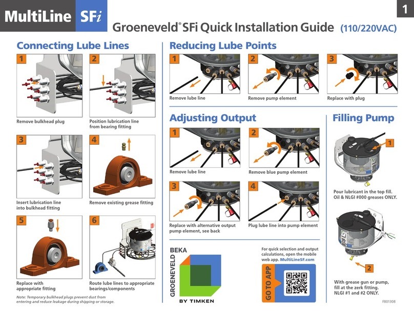
To connect to bulkhead ngs on the pump bracket follow steps 1-3 as shown above. Remove plug from bulkhead and push the line
rmly into the bulkhead. Again, ensure tubing is pushed rmly into connector. Test the assembly by pulling rmly on the line aer instal-
laon. Using the ‘Installaon Record’ sheet (see page 18) connect the lines to the corresponding numbered pumping elements.
Note: All damaged lubricaon lines should be replaced using genuine spare parts, failure to do so can cause system malfuncons and
major safety issues.
Output pressure
Maximum output pressure from each
pumping element 1740PSI/120 Bar
Standard pump elements for AXL pumps.
Part No. Output/stroke Color Size
MSF-P-R010 0.010 cc Red
Ø4mm
Push-Lock
MSF-P-G015 0.015 cc Green
MSF-P-Y025 0.025 cc Yellow
MSF-P-B040 0.040 cc Blue
MSF-P-G060 0.060 cc Grey
MSF-P-B100 0.10 cc Black
1
REMOVE
2
POSITION LUBRICATION
3
INSERT LUBRICATION
Making the Looms and Connecons
