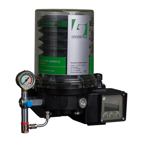
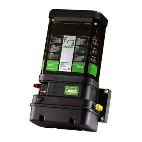
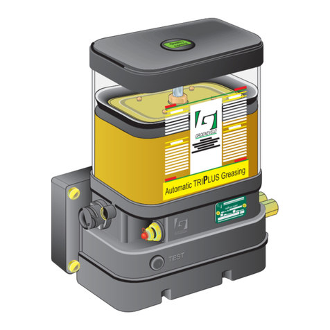
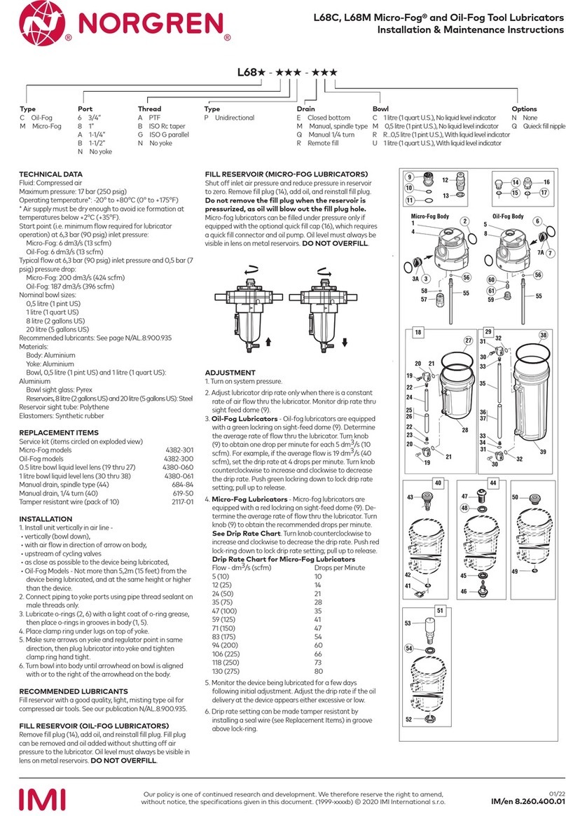
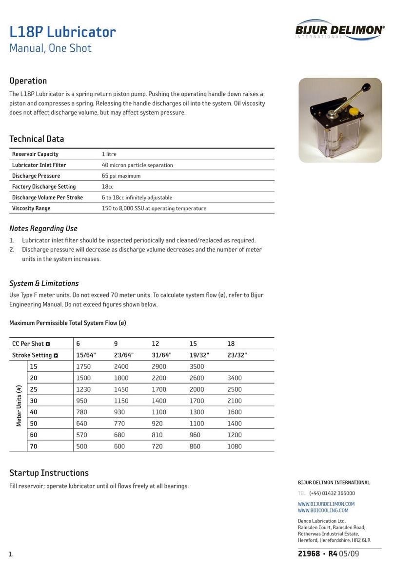
Groeneveld Twin-3 Configuration guide

General Manual
Automatic Greasing System
Twin-3
EG1703P03
Your efficiency is our Challenge!
Twin
ASC Form # 80-1052 Rev 9/2013

All rights reserved. No part of this manual may be copied and/or published by means of printing, photocopying,
microfilm or by any other means without prior written permission from Groeneveld. This applies also to the
drawings and diagrams appended.
Groeneveld reserves the right to change parts at any time, without prior or direct notice to the customer. The
contents of this manual may also be changed without prior notice.
This manual applies to the standard version of the product. Groeneveld cannot accept liability for any damage
arising from the use of specifications other than that supplied.
You are requested to contact Groeneveld technical service for information concerning adjustment, maintenance
work or repairs that is not described in this manual.
Whilst this manual has been prepared with the greatest possible care Groeneveld cannot accept responsibility for
any errors of the concequences of such errors.
General information
Type of manual General Manual
System Automatic Greasing System Twin-3
Document number EG1703P03
Date of issue January 2011
Revision 03

3Table of ContentsEG1703P03
Automatic Greasing System Twin-3
Date of issue : January 2011
Table of Contents
Preface - - - - - - - - - - - - - - - - - - - - - - - - - - - - - - - - - - - - - - - - - - - - - - - - - - - - - - - 5
1. General information - - - - - - - - - - - - - - - - - - - - - - - - - - - - - - - - - - - - - - - - - - - - - 6
1.1. Introduction- - - - - - - - - - - - - - - - - - - - - - - - - - - - - - - - - - - - - - - - - - - - - - - - - - - - - - - - - 6
1.2. The Twin automatic greasing system - - - - - - - - - - - - - - - - - - - - - - - - - - - - - - - - - - - - - - 6
2. Principle of operation - - - - - - - - - - - - - - - - - - - - - - - - - - - - - - - - - - - - - - - - - - - - 8
2.1. Introduction- - - - - - - - - - - - - - - - - - - - - - - - - - - - - - - - - - - - - - - - - - - - - - - - - - - - - - - - - 8
2.2. Greasing cycle - - - - - - - - - - - - - - - - - - - - - - - - - - - - - - - - - - - - - - - - - - - - - - - - - - - - - - - 8
2.2.1. Greasing cycle A - - - - - - - - - - - - - - - - - - - - - - - - - - - - - - - - - - - - - - - - - - - - - - - 8
2.2.2. Greasing cycle B - - - - - - - - - - - - - - - - - - - - - - - - - - - - - - - - - - - - - - - - - - - - - - - 9
2.3. Twin pump unit - - - - - - - - - - - - - - - - - - - - - - - - - - - - - - - - - - - - - - - - - - - - - - - - - - - - - 10
2.3.1. Control unit - - - - - - - - - - - - - - - - - - - - - - - - - - - - - - - - - - - - - - - - - - - - - - - - - 11
2.3.2. 5/2 way valve - - - - - - - - - - - - - - - - - - - - - - - - - - - - - - - - - - - - - - - - - - - - - - - - 14
2.3.3. Relief valve- - - - - - - - - - - - - - - - - - - - - - - - - - - - - - - - - - - - - - - - - - - - - - - - - - 14
2.3.4. Test push button - - - - - - - - - - - - - - - - - - - - - - - - - - - - - - - - - - - - - - - - - - - - - 14
2.3.5. Grease reservoir and its follower plate - - - - - - - - - - - - - - - - - - - - - - - - - - - - - 15
2.3.6. Minimum level switch- - - - - - - - - - - - - - - - - - - - - - - - - - - - - - - - - - - - - - - - - - 15
2.4. Distribution block and metering units- - - - - - - - - - - - - - - - - - - - - - - - - - - - - - - - - - - - - 16
2.4.1. Principle of operation- - - - - - - - - - - - - - - - - - - - - - - - - - - - - - - - - - - - - - - - - - 17
2.5. Pressure switch- - - - - - - - - - - - - - - - - - - - - - - - - - - - - - - - - - - - - - - - - - - - - - - - - - - - - - 19
2.5.1. Principle of operation- - - - - - - - - - - - - - - - - - - - - - - - - - - - - - - - - - - - - - - - - - 19
2.6. Signal lamp - - - - - - - - - - - - - - - - - - - - - - - - - - - - - - - - - - - - - - - - - - - - - - - - - - - - - - - - 21
2.7. Duty mode push-button - - - - - - - - - - - - - - - - - - - - - - - - - - - - - - - - - - - - - - - - - - - - - - - 21
2.8. Twin-3 display - - - - - - - - - - - - - - - - - - - - - - - - - - - - - - - - - - - - - - - - - - - - - - - - - - - - - - 22
2.8.1. Decimal dot of the 3-digit display - - - - - - - - - - - - - - - - - - - - - - - - - - - - - - - - - 23
3. System test - - - - - - - - - - - - - - - - - - - - - - - - - - - - - - - - - - - - - - - - - - - - - - - - - - - 24
3.1. Introduction- - - - - - - - - - - - - - - - - - - - - - - - - - - - - - - - - - - - - - - - - - - - - - - - - - - - - - - - 24
3.2. Single greasing cycle test - - - - - - - - - - - - - - - - - - - - - - - - - - - - - - - - - - - - - - - - - - - - - - 25
3.3. Multiple greasing cycle test - - - - - - - - - - - - - - - - - - - - - - - - - - - - - - - - - - - - - - - - - - - - 26
3.4. Fast automatic cycle session - - - - - - - - - - - - - - - - - - - - - - - - - - - - - - - - - - - - - - - - - - - - 27
3.5. Resetting the system - - - - - - - - - - - - - - - - - - - - - - - - - - - - - - - - - - - - - - - - - - - - - - - - - 27
4. Maintenance - - - - - - - - - - - - - - - - - - - - - - - - - - - - - - - - - - - - - - - - - - - - - - - - - - 28
4.1. General - - - - - - - - - - - - - - - - - - - - - - - - - - - - - - - - - - - - - - - - - - - - - - - - - - - - - - - - - - - 28
4.2. Periodic checks - - - - - - - - - - - - - - - - - - - - - - - - - - - - - - - - - - - - - - - - - - - - - - - - - - - - - - 28
4.3. Bleeding the pump- - - - - - - - - - - - - - - - - - - - - - - - - - - - - - - - - - - - - - - - - - - - - - - - - - - 28
4.4. Bleeding the system - - - - - - - - - - - - - - - - - - - - - - - - - - - - - - - - - - - - - - - - - - - - - - - - - - 29
4.5. Refilling the grease reservoir - - - - - - - - - - - - - - - - - - - - - - - - - - - - - - - - - - - - - - - - - - - 30
4.5.1. Grease recommendations - - - - - - - - - - - - - - - - - - - - - - - - - - - - - - - - - - - - - - - 30
4.5.2. Filling the reservoir- - - - - - - - - - - - - - - - - - - - - - - - - - - - - - - - - - - - - - - - - - - - 30
4.6. Finding malfunctions - - - - - - - - - - - - - - - - - - - - - - - - - - - - - - - - - - - - - - - - - - - - - - - - - 31
4.6.1. General - - - - - - - - - - - - - - - - - - - - - - - - - - - - - - - - - - - - - - - - - - - - - - - - - - - - 31
4.6.2. Recognizing malfunctions- - - - - - - - - - - - - - - - - - - - - - - - - - - - - - - - - - - - - - - 31
4.6.3. Malfunction finding table- - - - - - - - - - - - - - - - - - - - - - - - - - - - - - - - - - - - - - - 32
4.6.4. Retrieving a fault code message by signal lamp- - - - - - - - - - - - - - - - - - - - - - - 40
4.6.5. Malfunction finding procedures - - - - - - - - - - - - - - - - - - - - - - - - - - - - - - - - - - 41
5. Technical data - - - - - - - - - - - - - - - - - - - - - - - - - - - - - - - - - - - - - - - - - - - - - - - - - 44
5.1. Twin pump unit - - - - - - - - - - - - - - - - - - - - - - - - - - - - - - - - - - - - - - - - - - - - - - - - - - - - - 44
5.2. Signal lamp - - - - - - - - - - - - - - - - - - - - - - - - - - - - - - - - - - - - - - - - - - - - - - - - - - - - - - - - 45
5.3. Twin display - - - - - - - - - - - - - - - - - - - - - - - - - - - - - - - - - - - - - - - - - - - - - - - - - - - - - - - - 46
Table of Contents4EG1703P03
Automatic Greasing System Twin-3
Date of issue : January 2011

Automatic Greasing System Twin-3
Preface 5
Date of issue : January 2011
EG1703P03
Preface
This general manual gives a description of the Twin automatic greasing system. It aims at giving
insight in the system’s operation and possibilities. Furthermore, in this manual you will find the
technical data on several components of the Twin automatic greasing system.
In this manual the following icons are used to inform or warn the user:
Use of symbols
ATTENTION
Draws the user's attention to important additional information meant to avoid problems.
WARNING
Warns the user for physical injuries or serious damage to the equipment caused by improper ac-
tions.
Symbol Explanation
BK Black
BN Brown
BU Blue
GN Green
GY Grey
OR Orange
PK Pink
PS Pressure Switch
PU Purple
RD Red
WH White
YE Yellow

General information6
Date of issue : January 2011
Automatic Greasing System Twin-3
EG1703P03
1 General information
1.1 Introduction
With an automatic greasing system of Groeneveld all grease points of a vehicle or machine are
lubricated automatically at the correct moment and with the correct amount of grease. Because
greasing takes places while the vehicle or machine is in operation, the applied grease is spread
optimally over the whole surface to be greased. The greasing system requires no user intervention
to operate, apart from periodically replacing the grease in its reservoir.
Groeneveld’s automatic greasing systems are designed with the utmost care and tested rigorously.
This guarantees an extended operational life and error-free operation, even under the most
extreme operating conditions.
Proper installation, using the correct type of grease, and periodic checks are prerequisites for the
continual hassle-free operation of the system. The periodic checks, which take little time and effort,
can be performed during the normal maintenance of the vehicle or machine (during oil-
replacement, for instance). Careful selection of construction materials, makes the greasing system
itself nearly maintenance-free.
1.2 The Twin automatic greasing system
Groeneveld has developed a double-line automatic greasing system especially for the use of NLGI
class-2 grease. The Twin system ensures that all the disadvantages of the systems currently available
for class-2 grease are eliminated.
The Twin system has all advantages of the Groeneveld single-line systems. This means, for instance,
that the system is expandible trouble-free with grease points that are installed afterwards (extra
machine equipment).
The advantages of the Twin system:
• ingenuous and fast assembly;
• modular expansion possible;
• parts of the system can (temporarily) be coupled or uncoupled;
• clear malfunction reports;
• registration of possible malfunctions;
• the grease dosage can easily be adjusted per greasing point to the needs of that particular
greasing point;
• the grease dosage per greasing point remains constant under all circumstances.
ATTENTION
The automatic greasing system reduces the time and effort spent on manual greasing significantly.
However, do not forget that there may be grease points that are not served by the greasing system
and must still be greased by hand.

Automatic Greasing System Twin-3
General information 7
Date of issue : January 2011
EG1703P03
A
Groeneveld
Twin automatic greasing system comprises the following parts (see Figure 1.1):
1. An electric grease pump (plunger pump) with integrated grease reservoir and a digital
control unit with data storage facility
2. Primary grease line A
3. Primary grease line B
4. Distribution block
5. Metering unit
6. Pressure switch
7. Secundary grease line
Figure 1.1 System overview
TWIN
1
3
5
6
24
7

Principle of operation8
Date of issue : January 2011
Automatic Greasing System Twin-3
EG1703P03
2 Principle of operation
2.1 Introduction
In this chapter the principles of operation of the various parts of the Twin automatic greasing
system are discussed. The greasing cycle, pump unit, control unit, metering units, pressure switch,
signal lamp and Twin-3 display are discussed.
2.2 Greasing cycle
Every greasing cycle consists of four phases. The greasing cycles are performed alternately by the
grease lines-A and -B (see Figure 2.1). The 5/2-way valve, which is integrated in the pump housing,
determines which primary grease line is connected to the pump and which is connected to the
grease reservoir. The total greasing cycle has a predetermined time; the length of the four phases
depend on the circumstances. The different greasing cycles and phases are discussed below.
Figure 2.1 Overview of the various phases of the greasing cycle
2.2.1 Greasing cycle A
Pumping phase
The greasing cycle begins with a pumping phase. In this phase the grease is pumped from the
reservoir, through primary grease line-A, to the distribution blocks. The pumping phase ends when
the pressure at the pressure switch reaches a predetermined level. The time needed to reach that
predetermined pressure depends on various factors as temperature, grease consistency (thickness)
and the dimensions of the greasing system.
During the pumping phase, the metering units press a certain amount of grease (the dosage)
through the secondary grease lines to the grease points.
Cycle A Cycle B
pump
pressure
retaining
phase
pressure
decrease
phase
pause
phase
pumping phase pressure
retaining
phase
pressure
decrease
phase
pause
phase
5/2 valve
pressure path
primary line-A
pressure path
primary line-B
pumping phase

Automatic Greasing System Twin-3
Principle of operation 9
Date of issue : January 2011
EG1703P03
Pressure retaining phase
The pressure retaining phase follows the pumping phase; a period in which the pressure in the
primary grease line-A is maintained at a certain pressure. During the pressure retaining phase, the
metering units can deliver the grease dosage, which (for various reasons) was not yet delivered
during the pumping phase. The duration of the pressure retaining phase depends on the duration
of the pumping phase. This dependency is expressed in the parameter vmf, venting multiply factor.
Example: When the vmf is 1.0 the pressure retaining phase is the same length as the pumping
phase. When the vmf is set to 10.0, the pressure retaining phase is 10 times the length
of the pumping phase.
Pressure decrease phase
The pressure decrease phase follows the pressure retaining phase. In this phase, the pressure in the
primary grease line-A is decreased through the 5/2-way valve. To accomplish this, the control unit
switches the 5/2-way valve on, so the grease pressure in the primary grease line-A is decreased and
the grease flows back to the reservoir.
The duration of the pressure decrease phase is equal to that of the pressure retaining phase and
therefore proportional to the duration of the pumping phase. When the greasing system needs
more time to build up the required grease pressure (because of low temperature or grease with a
high viscosity), the system will also need more time to decrease that same pressure.
Pause phase
The pause phase is the period between the pressure decrease phase and the beginning of the next
pumping phase in line-B. The length of the pause phase is equal to the predetermined cycle-time
minus the length of the other phases. When the cycle-time is adjusted too short to perform a
complete greasing cycle, the program will ignore the cycle-time. The pumping-, pressure retaining
and pressure decrease phase will be performed completely. However the pause phase will be
omitted, because the predetermined cycle-time is exceeded. The greasing system begins directly
with the first phase of the next greasing cycle.
2.2.2 Greasing cycle B
Greasing cycle B begins when the pause phase of the former cycle A is finished. The control unit
restarts the pump. During pumping phase B and pressure retaining phase B, the control unit
switches the 5/2-way valve on, causing the pump to be connected to primary grease line-B. The
primary grease line-A is shut off from the pump during these phases and connected to the reservoir.
During the pressure decrease phase in primary grease line-B, the control unit switches the 5/2-way
valve (spring return) off, so the grease pressure in the primary grease line-B decreases and the
grease flows back to the reservoir.

Principle of operation10
Date of issue : January 2011
Automatic Greasing System Twin-3
EG1703P03
2.3 Twin pump unit
The Twin pump unit consists of various parts. These parts are shown in Figure 2.2.
Figure 2.2 Twin pump unit
The heart of the pump is an electrical-driven piston-pump. This pump consists of three radially-
placed fixed cylinders and pistons (5). The electromotor drives the axle through the mechanical
transmission (9). A cam (4) is fixed on the axle that moves the three pistons to and fro, so the grease
is pumped to the distribution blocks through the primary grease lines. In addition to the cam, the
axle drives the stirring gear (3) located at the bottom of the reservoir and pushes the grease
downwards. A compression channel is located between the pump and the grease channels to the
primary lines. A relief valve (14) and a 5/2-way valve (6) are located in the compression channel.
The relief valve is a protection that leads the grease back to the reservoir when the grease pressure
exceeds 250 bar. The 5/2-way valve determines the primary grease line-A or -B through which
greasing takes place. It has an important task in fulfilling the four phases of the greasing cycle (see
paragraph 2.2).
1
2
3
4
5
6
7
8
9
12
11
10
13
14
15
16
17
18
19
1. Follower plate
2. Grease reservoir
3. Stirring gear
4. Cam
5. Cylinder and pistons (3x)
6. 5/2-way valve
7. Primary grease line-A outlet
8. Primary grease line-B outlet
9. Mechanical transmission
10. Electro-motor
11. Control unit
12. Test push-button
13. Filler coupling with grease filter
14. Relief valve
15. Bleeding and grease overflow out-
let
16. Electric connector
17. Minimum level switch
18. Guide rod follower plate
19. Bleeding and grease overflow
channel, connected to the
bleeding and grease overflow
outlet (no. 15)

Automatic Greasing System Twin-3
Principle of operation 11
Date of issue : January 2011
EG1703P03
2.3.1 Control unit
The electronic control unit steers and controls the course of the greasing cycles. All system- and
program-parameters are stored in it. The control unit processes malfunction reports, gives possible
alarm reports and automatically records a log. All relevant incidents will be stored in the log.
All data in the control unit will always be retained, even when the power or system is switched OFF.
To view the log an Uni- or PC-GINA is needed.
The control unit is electrically connected according to the wiring diagram shown (see Figure 2.3).
The positive pole of the supply voltage (+15) is connected to pin-1.
As soon as the ignition is switched ON, the program cycle is started at the point where it was
interrupted during the preceding cycle.
If the preceding cycle was interrupted during the pumping phase by switching OFF ignition, this
pumping phase will be continued the moment ignition is switched ON again.
Figure 2.3 Wiring diagram with signal lamp
PUMP
L
T
BK
RD
OR
BU
GY
PU
P
I
+-
M
1+15
3
7PS
8
6K
5
PS
4 +SL
2GND
VAL1
PUMP
POWER
J5
VAL2
LOW
TEST
J8
34
1
2
3
4
5
6
7
8
9
10
11
22K
12V 20A
24V 10A
1. Electric motor of pump
2. 5/2-way valve
3. Minimum level switch
4. Test push-button
5. Control unit
6. Pump housing
7. Battery
8. Ignition switch
9. Pressure switch
10. Greasing cycle selector switch
11. Signal lamp

Principle of operation12
Date of issue : January 2011
Automatic Greasing System Twin-3
EG1703P03
Vehicles or machines of which the actual operation time is much shorter than the ignition time, the
connected grease points could easily get over greased. In order to prevent this, the interval timer
can be stopped for the time the vehicle or machine is not in operation, while the ignition is
switched ON. Figure 2.4 shows how to connect the control unit in this situation.
Pin-1 and -2 are, as in the other diagram, connected to ignition and ground. Pin-3 is the additional
connection for starting or stopping the interval timer on demand. Depending on the available
electrical connection at the vehicle or machine, the interval timer can be started when:
• power to pin-3 is switched ON
• power to pin-3 is switched OFF
• ground to pin-3 is switched ON
• ground to pin-3 is switched OFF
Please refer to the Twin-3 Uni- or PC-GINA manual for the necessary parameter settings in order to
activate one of the above mentioned possibilities.
Figure 2.4 Wiring diagram with command switch and Twin-3 display
TWIN
Automat c
Gea ing
System
SW TCH
PUMP
L
12V 20A
24V 10A
22K
12V 3A
24V 3A
T
BK
RD
GN
BU
GY
WH
YE
PU
P
I
+-
I
+
/
-
1+15
3
7PS
8
6K
5
PS
4 +SL
2GND
VAL1
PUMP
POWER
J5
J8
34
VAL2
LOW
TEST
1
2
3
4
5
6
7
8
9
10
11
12
13
14
1. Electric motor of pump
2. 5/2-way valve
3. Minimum level switch
4. Test push-button
5. Control unit
6. Pump housing
7. Battery
8. Ignition switch
9. Command switch (+ or -, normally opened or closed)
10. Pressure switch
11. Twin-3 display
12. Error signal output-1 (max 6W), -31 ground
13. Low level signal output-2 (max 6W), -31 ground
14. Additional in- output connection

Automatic Greasing System Twin-3
Principle of operation 13
Date of issue : January 2011
EG1703P03
Figure 2.5 Wiring diagram OEM pump with CANbus
IMPORTANT
The internal wiring of an OEM/CANbus pump is different from standard. Activating the CANbus
option in the control unit with a diagnosis device therefore will only be useful in combination with
such a pump (see internal wiring of pump connector pin-4 and -5).
PUMP
L
12V 20A
24V 10A
22K
120 Ohm 5% 1W
12V 3A
24V 3A
T
BK
RD
GN
BU
GY
PK
OR
P
I
+-
I
+
/
-
CAN
CPU
1+15
3
7PS
8
6K
5
PS
4L
H
2GND
VAL1
PUMP
POWER
J5
J8
34
VAL2
LOW
TEST
1
2
3
4
5
6
7
8
9
10
11
1. Electric motor of pump
2. 5/2-way valve
3. Minimum level switch
4. Test push-button
5. Control unit
6. Pump housing
7. Battery
8. Ignition switch
9. Additional switch (+ or -, normally opened or closed)
10. Pressure switch
11. CAN CPU

Principle of operation14
Date of issue : January 2011
Automatic Greasing System Twin-3
EG1703P03
2.3.2 5/2 way valve
When the 5/2-way valve is at stationary (not switched on by the control unit, see Figure 2.6),
greasing will take place through primary grease line-A and the pressure in primary grease line-B
will decrease and the grease will be lead back to the reservoir through return line RB.
Figure 2.6 5/2-way valve
When the 5/2-way valve is switched on by the control unit, the grease supply channel P will be
connected to primary grease line-B and primary grease line-A will be connected to return line RAin
the pump. Greasing takes place through primary grease line-B, the pressure in primary grease line-
A will decrease and the grease will be lead back to the reservoir through return line RA.
For an extensive description of the greasing cycle and the influence of the position of the 5/2-way
valve on the greasing cycle, see paragraph 2.2.
2.3.3 Relief valve
A relief valve is mounted in the grease line between the piston-pump and the 5/2-way valve (see
Figure 2.2/14). When the grease pressure exceeds 250 bar during the pumping phase, the relief
valve will redirect the grease to the reservoir.
The maximum grease pressure will be exceeded when:
• a malfunction of the pressure switch, which is mounted in the system, occurs;
• a malfunction in the cable of the pressure switch occurs.
The pressure switch is intended to end the pumping phase, as soon as the minimum required grease
pressure is reached.
2.3.4 Test push button
The grease system can be tested by starting one or more cycles by means of the test push-button
on the pump unit (see Figure 2.2/12). This button also can be used to reset the control unit.
P
A Primary greas line A (port A)
B Primary greas line B (port B)
P From pump
RAReturn line A to grease reservoir
RBReturn line B to grease reservoir

Automatic Greasing System Twin-3
Principle of operation 15
Date of issue : January 2011
EG1703P03
2.3.5 Grease reservoir and its follower plate
The reservoir (see Figure 2.2/2) is made of a transparant, impact-proof plastic that resists the affect
of variable temperatures and other enviromental influences.
The volume of the reservoir depends on its height. The maximum grease level is indicated on the
reservoir. A warning signal in the cabin indicates when the minimum level has been reached.
A follower plate (see Figure 2.2/1) is located in the reservoir, above the grease. This piston follows
the level of the grease. When the grease level falls, the piston also falls under the influence of a
draw spring. The grease follower plate locks out air and condensation, so preventing:
• oxidation of the grease;
• mingling of the grease with the water of condensation;
• saponifying of the grease.
The grease level in the reservoir can always be determined at a glance, because the grease follower
plate scrapes the walls of the reservoir. Also the follower plate prevents funnel-forming in the
grease, so the grease supply can and will be used in its entirety.
2.3.6 Minimum level switch
A minimum level switch monitors the grease level in the reservoir (see Figure 2.2/17). When the
grease reaches the minimum level, this switch will notify the control unit. At the beginning of every
following greasing cycle a signal lamp in the cabin will flash or the yellow and green LED along with
indication LO at the Twin-3 display is lit continuously as a warning that the reservoir has to be
refilled.

Principle of operation16
Date of issue : January 2011
Automatic Greasing System Twin-3
EG1703P03
2.4 Distribution block and metering units
Various types of metering units with the Twin greasing system are available, each with a different
grease output. Each grease point can receive the correct dose of grease per greasing cycle by a
careful choice of the type of metering unit.
Figure 2.7 Distribution block with metering units
The metering units are mounted on a distribution block per group. The distribution blocks are
deliverable with 2, 3, 4, 5, 6, 7, 8, 9, 12, 14, 18, 20, 21 or 22 ports (exits).
Grease points are connected to these ports through metering units and secondary grease lines.
Unused ports are sealed with a blind plug. A pressure switch can also be mounted into one of the
ports.
Because of their closed construction the metering units are exceptionally well suitable for use in
dirty and dusty environment.
The metering units and distribution blocks are made of brass or stainless steel. The various metering
units are distinguished from each other using numbers (see Figure 2.7/3). The table below is an
overview of the various metering unit numbers and their grease capacity.
Metering unit num-
ber
Grease capacity (cm³)
per cycle
Metering unit num-
ber
Grease capacity (cm³)
per cycle
00,025 70,350
10,050 80,400
2 0,100 8,5 0,700
30,150 91,000
4 0,200 10 2,000
5 0,250 11 4,000
60,300
2 4
4
8
712.01
43-07
100bar
4
3
12
1. Part number
2. Production week / year
3. Metering unit number
4. Pressure switch

Automatic Greasing System Twin-3
Principle of operation 17
Date of issue : January 2011
EG1703P03
2.4.1 Principle of operation
Two grease chambers are located in a metering unit (one for each primary grease line, A and B).
These chambers are filled with an exact amount of grease. When the actual greasing takes places
through one of both chambers, the grease is pressed from the chambers to the relevant grease
point. The principle of operation of the metering unit is explained in the four phases below.
Phase 1
In this phase the metering unit has not yet been filled with grease.
Figure 2.8 First phase
While in operation (system completely filled with grease) phases 3 and 4 will take place alternately.
Phase 2
During pumping phase A grease is pressed into channel A. While the grease pressure is built up,
piston (3) is pushed to the right, passed channel (1). The grease fills chamber (2) through channel
(1) and pushes piston (4) to the right.
Figure 2.9 Second phase
After a while, the pressure drops in the primary grease line-A (during the pressure decrease phase
of the greasing cycle). This has no influence on the metering unit.
ATTENTION
Do not open the metering units. Prevent intrusion of dirt and thus a possible cause of malfunction.
312 4
A

Principle of operation18
Date of issue : January 2011
Automatic Greasing System Twin-3
EG1703P03
Phase 3
During pumping phase B grease is pressed into channel B (6). While the grease pressure is built up,
piston (3) is pushed back leftwards, passed channel (8). The grease fills chamber (7) and pushes
piston (4) back to the left. The complete grease volume of chamber (2), left of piston (4), is pressed
through channel (1), piston (3), channel (9) and the secondary grease line (5) to the grease point.
Sphere (10) in the non-return valve is pushed back to clear the path to the secondary grease line.
Figure 2.10 Third phase
After a while, the pressure drops in the primary grease line-B (during the pressure decrease phase
of the greasing cycle). This has no influence on the metering unit.
Phase 4
In this phase the same happens as in phase 2. However chamber (Figure 2.10/7) is now filled with
grease. Piston (4) is pushed to the right while chamber (2) is filled. The complete grease volume of
chamber (Figure 2.10/7) is pressed through channel (8), piston (3), channel (9) and the secondary
grease line (5) to the grease points. Sphere (10) in the non-return valve is pushed back to clear the
path to the secondary grease line.
Figure 2.11 Fourth phase
74
3
19 106852
B
3 2 854 9 10
A

Automatic Greasing System Twin-3
Principle of operation 19
Date of issue : January 2011
EG1703P03
2.5 Pressure switch
The pressure switch notifies the control unit that sufficient pressure has been built up during the
pumping phase and stops the pump. When the required pressure is not reached, the pumping
phase is only ended after reaching the set maximum pumping time. An alarm will follow (signal
lamp).
Preferably the pressure switch is mounted on the distribution block, located the farthest from the
pump. This is done to be sure that the required grease pressure of 100 bar also reaches the last dis-
tribution block. When for practical considerations the switch is placed somewhere in the middle or
at the beginning of the greasing system, a switch with a higher switch-pressure is applied. Pressure
switches are delivered with switch-pressures of 100, 125, 150 or 175 bar.
2.5.1 Principle of operation
The principle of operation of the pressure switch is explained in three phases.
Phase 1
During this phase no pressure is on channel A and B. There is also no pressure in chamber (1). Spring
(10) pushes switch piston (2) to the left. The electrical contact (3 and 4) is open.
Figure 2.12 First phase
Phase 2
During pumping phase A grease is pressed into channel A. While the grease pressure is built up,
piston (6) is pushed to the right. Chamber (1) is connected to channel A (through the channels 7, 8
and 9).
As soon as the pressure in chamber (1) is more than the pressure force of the spring (10), piston (2)
goes to the right. The electrical contact (3 and 4) is closed by the contact plate (5).
B
A
12103
4

Principle of operation20
Date of issue : January 2011
Automatic Greasing System Twin-3
EG1703P03
Figure 2.13 Second phase
During the pressure decrease phase, as soon as the grease pressure in channel A is lower than the
pressure force of the spring, the connection of the electrical contacts is broken.
Phase 3
During pumping phase B grease is pressed into channel B. While the grease pressure is built up,
chamber (11) fills with grease (through channel 12). The grease pressure pushes piston (6) to the
left. Because of that the channel (8) is opened, causing the grease to flow to chamber (1) through
channel (7 and 9).
As soon as the pressure in chamber (1) is higher than the pressure force of the spring (10), the piston
(2) goes to the right. The electrical contact (3 and 4) is closed by the contact plate (5).
Figure 2.14 Third phase
During the pressure decrease phase, as soon as the grease pressure in channel B is lower than the
pressure force of the spring, spring (10) pushes piston (2) back to the left and the connection of the
electrical contacts is broken.
186725103
49
B
A
18612725103
4119
B
A
Other manuals for Twin-3
2
This manual suits for next models
1
Table of contents
Other Groeneveld Lubrication System manuals

Groeneveld
Groeneveld OnePlus Configuration guide

Groeneveld
Groeneveld TRIPLUS Installation instructions

Groeneveld
Groeneveld TWIN Configuration guide

Groeneveld
Groeneveld CompAlube Configuration guide

Groeneveld
Groeneveld EcoPlus Installation instructions

Groeneveld
Groeneveld CompAlube Installation instructions

Groeneveld
Groeneveld Multiline AC Series User manual

Groeneveld
Groeneveld TriPlus Trailer Configuration guide

Groeneveld
Groeneveld BreakAlube-3 Configuration guide

Groeneveld
Groeneveld Multiline AC F219157R03 User manual