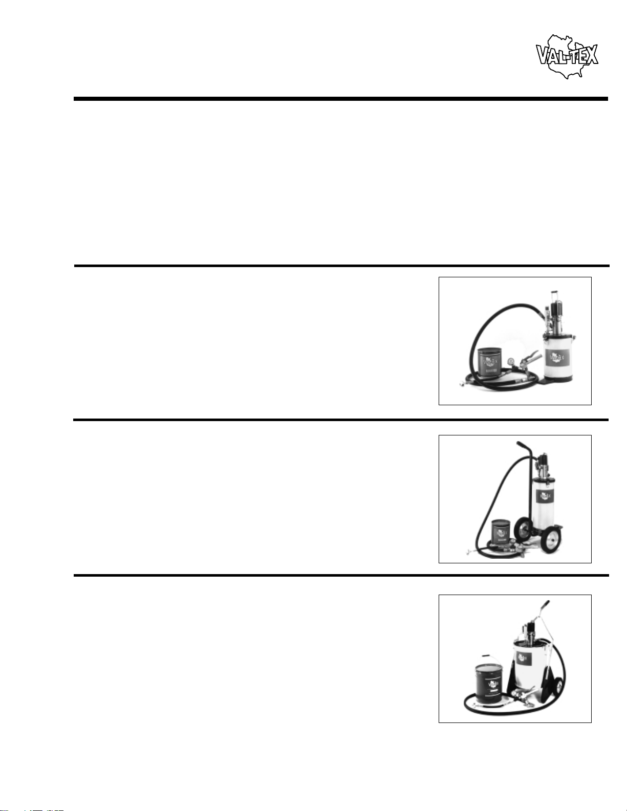
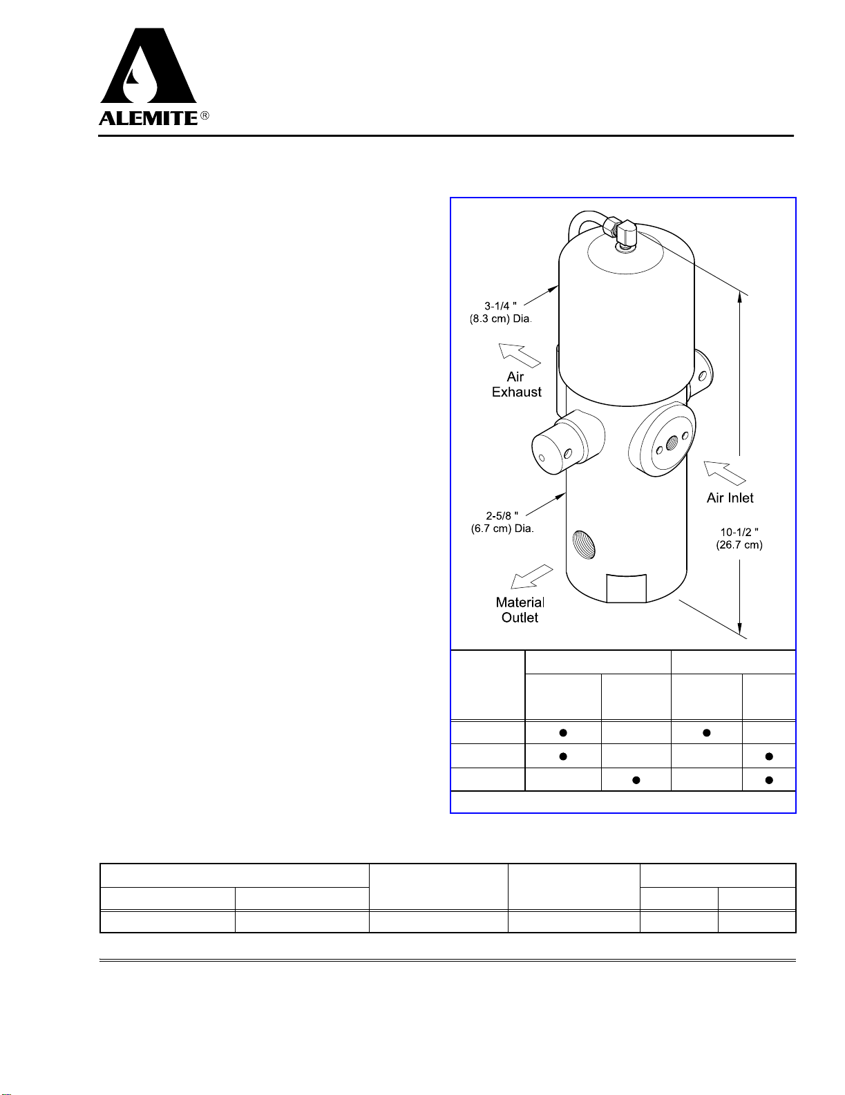
High-Pressure Pump (Stationary and Portable)
SER 8540-A1
Alemite Corporation 3 Revision (7-98)
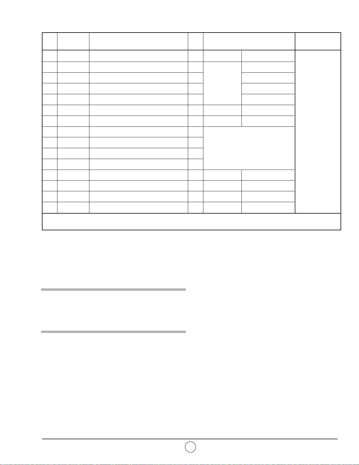
Item
No. Part No. Description Qty Notes Numeric Order
Part # (Item #)
18540-B Pump Assembly, High-Pressure 1 See SER
8540-B
6320-3 (4)
2 317875-7 Hose Assembly, Material 1
Model 8541-5
8540-B (1)
3 44734 Adapter, 3/8 “ NPTF (m) x 1/2 " -27 1
17804
(8)
4 6320-3 Valve Assembly, Control 1 See SER
6320-3
44734 (3)
5 B52752 Z-Swivel Assembly, High-Pressure 1 See
Figure 3
48018 (11)
6 315943 Bushing 1 B52752 (5)
7 338371 Cover Assembly 1
77009
(12)
8 Washer, 1/4 " 3
Included w/ 338371
77786
(10)
9 Washer, Lock, 1/4 " 3
170561
(13)
10 Capscrew, 1/4 " -20 x 1/2 " 3
172207-1
(9)
11 48018 Screw, Thumb, 1/4 " -28 x 1-1/8 " 3 315953 (6)
12 Washer, Internal Tooth Lock, 1/4 " 1 316315-5 (15)
13 Screw, 1/4 " -20 x 5/16 " 1 317875-7 (2)
14 338802 Plate, Follower 1 320998-B4 (7)
15 316315-5 Dolly Assembly 1 Model 8541-5 See SER
316315-5
338802 (14)
Legend
:
Part numbers left blank (or in
italics
) are not available separately
Assembly
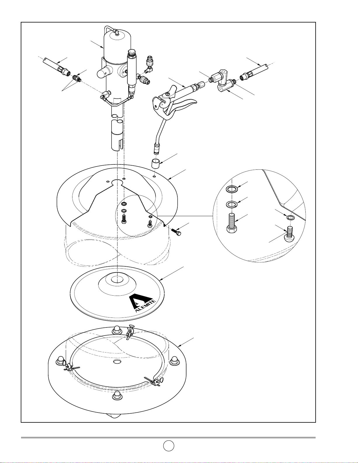
NOTE
: Refer to
Figure 2
for component
identification on all assembly procedures.
CAUTION
Select a clean environment for all assembly proce-
dures. Prevent contamination from foreign mate-
rial. Damage to components can occur.
Pump Assembly and Cover
IMPORTANT: Make sure to remove the pro-
tective cover from the inlet of Pump Assem-
bly (
1
).
1. Install Pump Assembly (
1
) into Cover Assembly (
7
).
2. Secure the Pump Assembly to the Cover with
Washers (
8
), Lock Washers (
9
), and Capscrews (
10
).
• Tighten the Capscrews securely.
Cover Assembly and Follower Plate
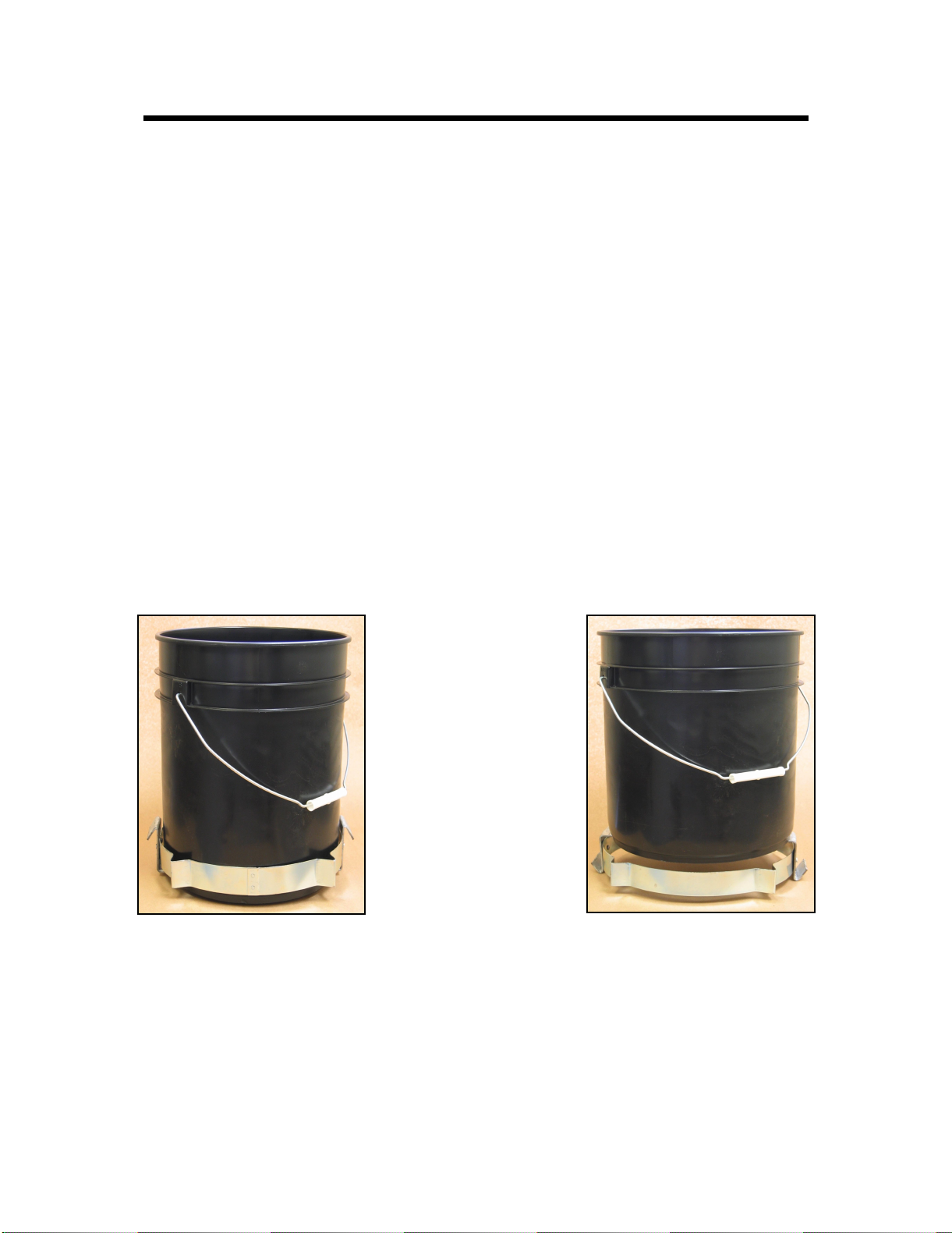
3. Place Follower Plate (
14
) onto the top of the product.
• With a wobbling motion, eliminate any air that may
be trapped underneath the Follower Plate. Force the
product through the hole in the center of the Plate.
4. Guide the pump tube into the Follower Plate and fit the
Cover onto the container.
5. Secure the Cover to the container with Thumb
Screws (
11
).
NOTE
: On model 8541-5, secure the con-
tainer to Dolly (
15
). Refer to SER
316315-5
for details.