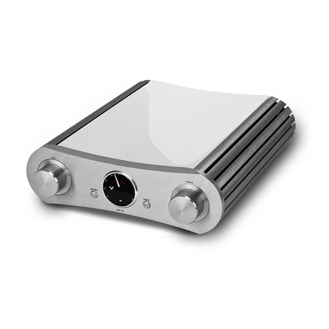
Trigon Epilog User manual

INSTRUCTION MANUAL
INTEGRATED AMPLIFIER
Epilog
dB
PEAK-L OFFSET TEMP MONO HF SPK-OFF PEAK-R
Epil og

TABLE OF CONTENT
1. PREFACE
2. General Description
2.1 Safety
2.2 Installation
2.3 Warranty and Service
3. Operation
3.1 Front Panel Controls
3.2 Connections –Rear Panel
3.3 Quick Start Instructions
3.4 Setup and Menu Structure
3.5 Unity Gain
3.6 EPILOG with DIRECTOR Remote Control
4. Modules
4.1 UNBAL-INPUT Module
4.2 BAL-INPUT Module
4.3 UNBAL-OUTPUT Module
4.4 BAL-OUTPUT Module
4.5 PHONO-INPUT Module
4.6 DIGITAL-INPUT Module
5. What if...
5.1 ... nothing happens ?
5.2 ... there's no sound ?
5.3 ... it hums ?
5.4 … errors are made by man or machine?
6 . Specifications

1. PREFACE
Dear Customer,
Thank you for choosing an Epilog integrated amplifier. This product is
manufactured with care under strict quality control and is a perfect example of state-
of-the-art precision technology. Even if you are familiar with hi-fi equipment, please
take a moment to study these instructions carefully and follow the instructions
contained therein. Keep this manual for future reference; it is intended as a tool to
help you make the best use of your new amplifier.
Enjoy your new integrated amplifier!
Best wishes from your TRIGON - team.
2. GENERAL DESCRIPTION
Epilog is an integrated amplifier that can be individually adjusted in the pre stages
to the needs of the user by the use of modules. It can be inserted up to five modules
in the back of the amplifier. Due to the modular design it is also possible to respond
to the latest technical developments. The choices are unbalanced and balanced input
modules, a phono module with MC / MM sensitivity, DAC module with two SPDIF
Coax inputs, one optical input and a USB input and line output modules in
symmetrical and asymmetrical design. The modules can be combined arbitrarily. The
position in the slots can be freely selected. If necessary, a plurality of identical
modules may be used. The modules offered will be expanded as new applications or
technical progress requires. In these cases, not a completely new amplifier must
immediately be purchased, but only the corresponding module.
So the Epilog with comparatively little investment can always be kept up to date
or be adapted to new requirements
In the class AB output stages of the so-called double mono principle each channel
gets its own transformer and its own electrolytic capacitor package. In this manner,
the mutual interference between the stereo channels is reduced to a minimum.
The bandwidth of the amplifier is very well designed to allow a time accurate
transmission of all frequencies up to the upper limit of hearing. This is made possible
by the use of symmetrical cascode amplifiers and measured pairs of bipolar power
transistors. Each channel used six couples. Therefore Epilog is able to drive
speakers with a minimum impedance of 2 Ohm.
Always wakes sensitive safety electronics to the welfare of speakers and amplifiers.
A dimmable turn off and on display at the front informed about the currently operating
conditions.
The operation of the device can be done either manually directly at the Epilogue or
with the IR Remote Control Director. Together with our network multimedia player

Chronolog it is also possible to operate the Epilog with a tablet computer or
a smart phone.
From time to time it may be necessary to update the control software contained in
this basic unit. On the rear panel is for this purpose a USB socket (26) to which you
or your dealer can connect a computer to load the latest firmware into the memory of
the integrated amplifier. This software is provided for free on our website. Software
updates will always be necessary, if a newly developed module is to be operated,
which did not even exist when buying the Epilog. In the Info menu of the
Epilog the currently version can be read. On our website you can then check
whether your device already has the latest software, or whether an update is needed.
The massive cabinet of the Epilog consists of 2mm sheet steel and solid
aluminum of various thicknesses. The cover, for example, consists of a sandwich of
steel and aluminum and is in the important frequency range acoustically "dead".
Due to the complex cabinet construction sound may be best avoided by
microphonics.
2.1 Safety
TRIGON ELEKTRONIK GMBH assumes no liability for any damage caused by
improper handling, or failure to follow safety instructions.
Amplifiers must not be installed in close proximity to heat sources such as radiators,
stoves, high power light sources, open flames, etc... and should not be exposed to
severe shocks or vibrations.
Do not connect any electronic device to AC mains immediately after transport from
the cold into a warm environment. Condensation may occur and cause damage to
the device. Please wait until the unit has reached room temperature.
The amplifier should not be exposed to direct sunlight.
Make sure to install the unit with enough space for proper ventilation.
Never operate the equipment without the protective housing cover. Before opening
the unit remove the AC plug from the socket.
Never attempt to bypass the fuse. Please replace a blown fuse only with a fuse of the
same type and value.
No user serviceable parts inside. All maintenance or repair must be performed by
authorized and specially trained personnel only. Tampering and damage caused by
improper use or unauthorized intervention will void warranty.

Please turn amplifier off before connecting cables and/or other components.
The mains voltage must be between 100V and 240V AC.
Use only attachments and accessories specified by the manufacturer and intended
for this purpose.
To clean the cabinet, use only a damp cloth if possible. Do not use corrosive or
abrasive cleaning fluids. Unplug the unit before cleaning. Be careful not to
accidentally damage or loosen any wiring when cleaning. Check all connections for
proper fit before re-connecting the Epilog to the grid.
WARNING! Always make sure that no liquids enter the interior of the device!
2.2 Setup
After unpacking, first check the equipment for shipping damage. If you notice any
damage, please immediately contact your dealer. Then check the contents of two
boxes to be complete.
You should see, besides the EPILOG:
−one Epilog instruction manual -
−one warranty registration form -
−one module removal tool -
The amplifier should be installed level and in a dry location. Always ensure good
ventilation. Please be aware that strong magnetic fields, such as caused by halogen
or fluorescent light transformers can cause hum –it is recommended to keep a
minimum distance of 1m (3'). Avoid direct sunlight and proximity to heat sources.
2.3 Warranty and Service
By choosing the Epilog integrated amplifier, you have purchased a high quality
and technologically advanced product. In order to meet TRIGON's requirements,
every product must undergo numerous quality tests in every stage of production and
a rigorous outgoing inspection. Furthermore, TRIGON ELECTRONICS GmbH offers
a limited 3-year warranty on all products. This warranty covers the repair or
replacement of defective components. Warranty repair is usually done at the factory.
Further claims are excluded.
The warranty excludes all damage caused by improper installation, improper
operation or resulting from repairs by unauthorized dealers and/or individuals.
Furthermore, this warranty does not cover units with obliterated or missing serial
numbers. Likewise, shipping damage or damage caused by accidents is not covered
under warranty.

Please make sure to complete the included warranty card. The 3-year warranty
period starts from the date of delivery by the dealer. Keep the warranty card and
proof of purchase.
3. Before You Begin
After unpacking the preamp and power supply, both components should be allowed
warm up to ambient temperature. Especially during the cold season humidity may
form inside a component as it is moved from the cold to a warm environment.
Epilog
Front View
1
2
3
4
5
6
7
8
910
11
12 13 14 15 16 17 18 19
dB
PEAK-L OFFSET TEMP MONO HF SPK-OFF PEAK-R
Epil og
Once the devices are acclimatized, we recommend that you first get acquainted with
your new Epilog integrated amplifier.
The first step will be to plug the included TRIGON VOLT power cord to the power
imput socket (24) at the rear side and the AC plug to the mains. Now turn on the
power supply with the switch (23) on the back.
The Epilog is now in standby mode, and the LED (2) on the front panel of the
power supply will be lit dimly.
Epilog
Rear View

CONSUMPTION 40 - 850W
handmade by
in GERMANY
INTEGRATED AMPLIFIER EPILOG
SPEAKER
RIGHT CHANNEL SPEAKER
LEFT CHANNEL
- -
+ +
MAIN POWER SERVICEIR-CON
REMOTE 10V DC
CAUTION
PHONO MM/MC DAC
L
A OPT.
R
B USB
REC-OUTPUT
L
REC
R
UNBAL-INPUT
L
B A
R
BAL-INPUT
L
R
BAL-OUTPUT
L
R
20
22
20
23
24
21
27
20
25
20
26
20
28
To power the Epilog on completely, press the on-off button (1) on the front of
Epilog. LEDs (2) on the front panel flashes while a few relay click softly. Once the
front panel display turns on, the Epilog is ready.
Now is a good time to get familiar with the basic functions and operation of the
Epilog before proceeding to hook the integrated amplifier up to your system.
CAUTION: Before you start making any connections, you should - as always when
working on the wiring - turn off the Epilog, as well as the other devices in the
system! Do not connect or disconnect RCA plugs to/from a UNBAL INPUT while the
Epilog is powered up, since with this type plugs the signal connection makes
contact before the ground, which may cause a very strong buzzing sound which can
under certain circumstances damage your speakers!
3.1 Front Panel Controls and Display
We've tried to limit the number of control elements in accordance with the motto "as
much as necessary, as little as possible". An important design consideration for the
Epilog integrated amplifier was to keep the basic functions easy to use and
intuitive –e.g. anyone is likely to associate the large knob (3) with the volume setting,
the keys (7) and (8) with inputs selection, and the button (1) for turning the Epilog
on or off.
Individual Elements:
(1) On –Off switch
Turns the Epilog on or off. When power indicator LED (2) is not lit, the standby
function is not activated by switch (23) or the amp is not connected to the mains.

NOTE: We have the Epilog equipped with a very low-power standby power
supply. The power consumption is less than 1 watt in standby mode, ie you can
always leave the Epilog connected in standby mode to mains without completely
power off using the power switch (23).
But if you once do not want to use the Epilog for a longer time (holydays, etc.),
you can of course turn off the power completely by switch of the mains to the switch
(23).
In severe storms with lightning danger is always recommended beyond the mains is
removed, ie: pull the plug!
(2) Power indicator LED
This LED illuminates when the Epilog is connected to the mains and switch (23) is
switched. Now, when the on-off switch (1) is pressed, this LED flashes until the
Epilog is ready.
(3) Volume knob
This knob adjusts the volume. It is an electronic pulse encoder, which forwards its
signals to a microprocessor. The microprocessor controls the signals to each output
module where the actual volume adjustment is made.
By pressing the volume knob the MUTE function is called, ie the volume is set to a
minimum value. Displayed the MUTE function is the fact that instead of numbers for
the selected volume, only four strokes are represented.
dB
Another push on the knob or turning the volume knob raises the MUTE function off
again and the previous volume level is restored.
(4) Volume Display
This LED display indicates in dB the volume level, the value is relative to the level of
the input signal.
With the remote controller Director the display can be switched off if you want to
have displayed only the volume level when you make a change.

The display can be turned off with the remote controller in two stages. When you first
press the display button on the Director the display (5) will switch off. In the
second pressing, the volume indicator (4) will switch off. A new key operation
switches both displays (4and 5) on again.
(5) Display:
The display gives you information about the different operating states of the
Epilog.
It can switch off by the remote controller Director, if you only want to see
information when you make a change.
(6) Button Menu up
Use this button to navigate through the setup menu. Refer also to Chapter 3.4
(7) Button Input Selection
With this key you can dial down the input module. In addition, this key also navigates
in the settings menu. Read more details about that in Chapter 3.4.
(8)Button Input Selection
With this button you can select the input module upward. In addition, this key also
navigates in the settings menu. Read more details about that in Chapter 3.4.
(9) Button
When this button is pressed, the MONO function is turned on. Another push switches
back to STEREO.
(10) Button Menu down
Use this button to navigate through the setup menu. See also Chapter 3.4.
NOTE: There will probably be in the future modules that rely on the keys (6, 7, 8, 9,
10). For details, refer then to the descriptions of the modules.
(11) LED PHONES
This LED is lit when the speaker relays are switched off in the menu [OFF] so you
can enjoy the music through headphones without speakers.

(12)Phones Output
Into this jack you can plug in a 6,3mm headphone. The impedance of the
headphones should not be less than 32 ohms.
(13 und 19) LED PEAK
These LEDs illuminate when the amplifier is overdriven and distorted signals are
output to the speakers. Momentary flash of these LEDs can be tolerated, but if these
LEDs should light up more often, so you should reduce the volume to protect both,
your speakers and the amplifier.
(14) LED OFFSET
When this LED is lit, the amplifiers output is a harmful direct current (DC offset).
Epilogue then instantly disconnects the speaker from the amplifier to prevent damage
to the speakers. In general, such an offset occurs at a defect in the final output stage,
ie you should have to check the amplifier at the service.
(15) LED TEMP
When this LED is lit, the permissible temperature of the output stage heat sink is
exceeded. Epilog switches the speaker off and LED (18) lights in addition for
control. Once the heat sink has cooled down to a few degrees Celsius below the
allowable temperature, the speakers are switched back on and the LEDs (15) and
(18) also switch off.
(16) LED MONO
This LED lights up when the monaural playback mode is turned on. This can be done
by holding down the button (9) or by the corresponding means of appropriate key on
the remote control. A further press of this button triggers the mono sound and LED
(16) disappears.
(17) LED HF
The frequency bandwidth of Epilog is very wide. Therefore, under certain
circumstances the output stages can start oscillating. A not perfectly matched
combination of speaker cable, crossover and loudspeaker chassis can form a
resonant circuit which, in conjunction with a broadband amplifier, can built an
oscillator. As these high frequencies are mostly beyond the threshold of human
hearing, but overloads unnecessarily the amplifier and the tweeter of the
loudspeaker, the speaker relay is switched off at such high frequencies. LED (17)
and (18) lights. After a few seconds the speaker is switched on again.

But should again high-frequency oscillation occur, the speakers are switched off
again and the LEDs (17) and (18) lights on again.
In general, the oscillation disappears by using a different speaker cable.
But it wants to work with the original cable, please use a RC circuit (Snubber)
connected direct at the speaker terminals. This can help to prevent oscillating at the
power stage.
(18) LED SPK OFF
This LED is lit when the speaker relays are switched off. The speaker relays are
switched off when the protection mechanisms mentioned above, but can also be
turned off manually when you want to listen to music through headphones and to
remain speakers silent. The speaker relay can be turned on and off in the menu
[OFF].
When the speakers are turned off in this menu, even the LED (11) via the headphone
jack (12) lights up additionally.
3.2 Connections on the back
Up to five modules (20) can be inserted at the back of the Epilog main chassis.
The REC OUTPUT module (21) can not be removed or moved to another location
because it houses the preamplifier for integrated amplifiers.
At least one input module is required to start operating the epilogue. Is this not the
case, so you get a message on the display (5).
Two analogue input modules the standard feature of the Epilog.
(22 und 28) Speaker jacks
Connect the speakers to these terminals. The impedance of the connected speakers
should not be less than 2 ohms.
(23) Standby Power Switch
With this switch the mains connection is established to the Epilog. However, the
Epilog is only by pressing the switch (1) fully turned on.
Does not press down switch (1) the Epilog is in standby mode, which is also
indicated by LED (2).
(24) Mains Jack

Here the power cord is plugged. Always pay attention to the correct mains voltage.
As standard, the epilogue is set for a mains voltage of 230 V AC. Have been set the
Epilog for different voltages, then corresponding notes are (sticker) at the amp.
(25) IR-CON Jack
An external IR controller can be connected to this jack. If the Epilog is situated at
a place where he can not receive infrared remote control commands, these
commands can be leaked via a small external IR receiver. This receiver is available
as an optional accessory.
(26) USB-SERVICE Jack
Over time, other new modules are developed, which however, always need the right
software to control. So if like to use a later newly developed module in your
Epilog, we created an opportunity to update the control processor with the
currently valid software. Please note that you find the latest software version at our
web site. There is the current software version available for download.
In the Epilog SET menu is a submenu "Info" where you can get information about
the currently software version of your Epilog.
The required software for the update procedure and a detailed description of that
procedure is also made available on our Website.
(27) REMOTE 10V Jacks
If you have connected to the Epilog another power amp or active Subwoofer, and
this amp has a DC 10V remote input, an additional 10V DC signal is available at this
jack to switched on and off synchronous with the Epilog.
3.3 Quick Start Instructions
For the impatient among you who already have some experience with high-end
amplifiers, here's a short guide to get to the music quickly:
•Hook up all devices
•Connect to AC mains and switch on the power switch (23) on the mains power
switch.
•Turn the Epilog on with the standby switch (1)
•Select source device with the input selector buttons (7) and (8)
•Set desired listening level with volume knob (3)
•Done!

3.4 Settings and Menus
The concept of the Epilog provides an intuitive user interface. Nevertheless, this
component provides useful additional features that are "hidden" in sub-menus.
To fully take advantage of the Epilog´s capabilities, we recommend taking the
time to read the following.
On power-up:
During power-up cycle the Epilog display will generally read as follows:
The microprocessor is checking which modules are available. There must always be
at least one input module present to ensure useful configuration, otherwise you may
get the following error message:
In that case please shut down and disconnect the Epilog from AC mains and
verify that the respective module is present and properly installed, or insert the
necessary module(s).
Make sure that at least one input module is installed!
With at least the minimum number of modules installed, the display will read as
shown in the following picture:

dB
Display structure:
The first line of the display indicates the number of the first occupied slot and the type
of module present. As long as no specific name for an input has been set, it will be
automatically designed as INPUT 1 in the second line of the display.
The third line indicates the sub-menus for the configuration of the module and
general setup. E.g. Sub-menu for configuring the input modules [IN], sub-menu for
the configuration of the output modules [OUT], sub-menu to select the source for
record out [REC] and a sub-menu for basic settings [SET].
A red numeric LED display shows the volume level in dB.
Basic Operation:
You can start enjoying music as soon as the unit is turned on. All that is need to
select an active input and the desired volume, without having to go to any sub-menu.
The keys (7) and (8) toggle between inputs. Use the volume knob (3) to set the
desired volume. That's all you need to get started.
Menus:
To access the menus press the button (10). This will recall the previously selected
menu. High-light the menu to be edited with the buttons (7) or (8). Suppose we want
to edit the input setting menu [IN], we see the following message:
dB

Use key (7) to navigate to the next menu to the right, e.g. [OUT]
Likewise, key (8) takes you in the opposite direction (left).
Editing the [IN] Menu:
After high-lighting the [IN] menu enter the desired menu with key (10) to get the sub-
menu screen below:
Now you are in the [IN] sub-menu, where you can edit the following settings:
1. Input selection [■] INPUT 1 SLOT 1
2. Activate or de-activate input [ ] Enabled YES
3. Adjust input trim [ ] Offset 0.0 dB
4. Name input [ ] Name - - - - - - - - -
[■] INPUT 1 SLOT 1
Use the first line to select the input to be edited with keys (7) and (8).This line also
shows in which slot the selected module is installed so that you can assign the input
exactly. Use button (10) to navigate to the next item.
[■] Enabled YES
Key (7) disables the selected input. Display: [■] Enabled NO
Key (8) enables the selected input. Display: [■] Enabled YES
[■] Enabled NO
This function is useful if you do not use an input. When you toggle between
inputs the disabled input is skipped.
Press key (10) to select the next item.
[■] Offset 0.0 dB
This sub-menu allows the level setting of individual inputs to match the level of other
sources to compensate for differences in playback volume when changing inputs.
Note that levels can only be reduced - choose as a benchmark the weakest source
and adjust for louder source devices in this menu. Maximum attenuation is -12dB,
which should be sufficient in most cases.

Press key (10) again to select the next item.
[■] Name - - - - - - - - -
Select a name for the selected input from a list with keys (7) and (8). This name will
be displayed when that input is selected. If no name is chosen - - - - - - - - - INPUT
will be displayed.
To exit the input menu press the key (6) repeatedly, until you get back to USER
mode.
dB
Display in USER mode
Assuming that you are currently in "user mode" and you want to edit the start menu,
press the key (10), and navigate using the buttons (7) and (8) to high-light the [OUT]
sub-menu and get the following screen display:
dB
Enter the [OUT] sub-menu by pressing the key (10) .The display will show:

Now you are in the [OUT] sub-menu, where they can make the following
adjustments:
1. Selecting the output to be edited [■] OUTPUT 1 SLOT 8
2. Reverse cannels [ ] Reverse NO
[■] OUTPUT 1 SLOT 6
On the first line select the output be edited with the keys (7) and (8). In this line you
can also see the slot in which the module is installed, so that you can assign the
output as desired.
[■] Reverse YES/NO
This feature allows you to swap the left and right channels with the key (7). With key
(8) the channel swap will be reversed to normal. To exit the Output menu, press key
(6) repeatedly until you are back in user mode.
Editing the [REC] menu:
Assuming that you are currently in "user mode" and you want to edit the Record
menu, press the key (10). Navigate using the buttons (7) and (8) until you see the
[REC] screen displayed as shown here:
dB
Enter the [REC] sub-menu by depressing key (10)

This menu allows to link a specific input to the Record Out connectors on the
"UNBALANCED OUTPUT" module, when installed. This function is only possible if at
least one module "UNBALANCED OUTPUT" is installed in a slot. Using the keys (7)
and (7) you can select the input to be fed to the REC OUT connectors.
To return to user mode press key (6) repeatedly.
Editing the [SET] menu:
From "user mode" navigate to the SETUP menu by pressing the key (10) and using
the buttons (7) and (8) until [SET] is high-lighted.
dB
:
Enter the sub-menu with key (10) und see following screen displayed:
dB
You are now in the [SET] menu, where you can make the following adjustments:

1. Speaker ON / OFF [■] Speakers ON
2. Set initial volume level [ ] Vol. Base Level
3. Adjust stereo balance [ ] Balance
4. 10V Trigger On/Off [ ] 10V Remote
5. Adjust display brightness [ ] Brightness
6. Select language [ ] Language ENGLISH
7. Dsiplay status information [] Infos
8. Reset to Factory Default [] Reset Settings
The [SET] menu contains three pages.
Various sub-menus can be accessed with key (10) (down) and key (6) (up).
[■] Vol. Base Level
This function allows setting the initial volume level assumed by the EPILOG upon
turn-on.
This value can be set with the volume knob (3) or with keys (7) und (8).Leaving this
sub-menu stores the setting.
[■] Balance
Set the L/R channel balance. This value can be adjusted using the volume knob (3)
with the keys (7) and (8).
[■] 10V Remote ON/OFF
Enable or disable the10V trigger output with keys (7) and (7) for remote switching of
associated equipment (e.g. power amplifiers, powered speakers, etc...) equipped
with this feature. The control voltage is output at the jack (27) on the rear panel.
[■] Brightness
The intensity of the front panel display can be adjusted from this sub-menu. Note that
the text displays (5) as only four intensity levels, whereas the volume display can be
adjusted from 10% to 100%.
Use this sub-menu to adjust the display brightness. Adjust with volume knob (3), or
with keys (7) and (8). The adjustment is stored when exiting this sub-menu.
[■] Language
Select the display language with keys (7) and (8).
(Currently two choices are available: German (Key 7) and English (Key 8))
[■] Infos
For this sub-menu press key (8) to display the currently installed software version.

The currently installed Software version is displayed in the first line, after the
TRIGON logo.
The second line [INS] displays the information about installed input modules and
number of available inputs.
The third line [OUTS} displays the information about installed output modules and
number of available outputs.
Pressing the key (8) again does plays information about the modules installed in the
individual slots.
In this example: Slot 1 contains a balanced input module with hardware revision 0 and software
revision 0. This module has one input.
Use keys (7) and (8) to get detailed information on every slot.
Press key (6) to exit the info sub-menu and go to the next sub-menu.
[■] Reset settings
In the event that you want to reset the Epilog to factory default settings, depress
button (9) in this menu for at least 5 seconds. The Epilog will display a count-
down sequence and then re-boot. The Epilog then reverts to normal playback
mode.
Table of contents
Other Trigon Amplifier manuals

