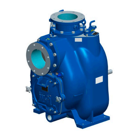
Trillium Roto-Jet RO-FT Series Instruction manual

Document Name: IOM-ROFT-EN Page | 1
Revision 2 Copyright © 2017, Trillium Pumps USA, All rights reserved
Roto-Jet© RO-FT Pumps
Installation, Operation & Maintenance Manual
Roto-Jet© is a registered trademark.
The document may contain information that is private, confidential and/or privileged. The document must not
be copied in whole or in part, in any form or by any means, and the information in it must not be disclosed to
any person, or used for any purpose other than the specific purpose for which it has been provided, without the
prior written consent of the company.

Document Name: IOM-ROFT-EN Page | 2
Revision 2 Copyright © 2017, Trillium Pumps USA, All rights reserved
Roto-Jet© RO-FT Pumps
Installation, Operation & Maintenance Manual
Revision Page
Revision
Description
Reviewed
Authorized
Date
Rev 0
Initial Release
Bryce Neilson
Kelly Wardell
4-28-15
Rev 1
RO-FT-F Update
Kelly Wardell
2-2-17
Rev 2
Branding Update
Lane Larsen
1-26-22

Roto-Jet© RO-FT Pump
Document Name: IOM-ROFT-EN Page | 3
Revision 2 Copyright © 2017, Trillium Pumps USA, All rights reserved
Table of Contents
1. Introduction ..................................................................................................................................7
1.1 Scope of the Manual............................................................................................................................7
1.2 Intended Audience ..............................................................................................................................7
1.3 Disclaimer ...........................................................................................................................................7
1.4 Overview of the Manual.......................................................................................................................8
Table 1-1 manual organization................................................................................................................8
1.5 Glossary of Abbreviations...................................................................................................................9
2. Safety...........................................................................................................................................10
2.1 Symbols ............................................................................................................................................10
2.2 Important Information ........................................................................................................................10
2.3 Operating Conditions.........................................................................................................................12
2.4 General Safety ..................................................................................................................................12
2.5 Emergency Procedures.....................................................................................................................13
3. Technical Data............................................................................................................................14
3.1 Pump Identification............................................................................................................................14
3.1.1 Nameplates................................................................................................................................15
3.1.2 Model Number Description.........................................................................................................16
3.2 Torque Tables...................................................................................................................................16
12.8.4 Attach Pitot tube to seal plate ........................................................................................................17
3.3 Oil Pans and Gear ratios...................................................................................................................18
3.4 Gear and Bearing Lubrication............................................................................................................18
3.5 Materials............................................................................................................................................19
3.6 Dimensional Drawings.......................................................................................................................20
3.7 Section Drawings ..............................................................................................................................22
3.8 Seal Selection Information.................................................................................................................29
3.9 General Arrangement Drawings ........................................................................................................29
4. Description..................................................................................................................................32
4.1 Introduction to RO FT Pump..............................................................................................................32
4.2 Component Descriptions...................................................................................................................32
5. Transportation and Storage ......................................................................................................33
5.1 Transportation Requirements............................................................................................................33
5.1.1 Pre transport Requirements........................................................................................................33
5.2 Storage..............................................................................................................................................33

Roto-Jet© RO-FT Pump
Document Name: IOM-ROFT-EN Page | 4
Revision 2 Copyright © 2017, Trillium Pumps USA, All rights reserved
5.2.1 Short Term Storage (up to 2 months).........................................................................................33
5.2.2 Rotor Drain Process ........................................................................................................................34
5.2.3 Long Term Storage (up to 24 months)........................................................................................35
5.3 Prior to Start-up.................................................................................................................................35
6. Installation ..................................................................................................................................36
6.1 Installation Safety..............................................................................................................................36
6.2 Pump Working Envelope...................................................................................................................36
6.3 Foundations ......................................................................................................................................37
6.4 Grouting and Base Installation...........................................................................................................37
6.5 Alignment..........................................................................................................................................38
6.5.1 Alignment checks.......................................................................................................................39
6.5.2 Alignment measurement guidelines............................................................................................39
6.5.3 Couplings...................................................................................................................................40
6.6 Piping................................................................................................................................................40
6.6.1 Bolt Tightening Procedure..........................................................................................................41
6.7 Before Start Up..................................................................................................................................44
6.8 Guards..............................................................................................................................................44
6.9 Bypass/Filtration System...................................................................................................................45
6.9.1 Bypass System...........................................................................................................................45
6.9.2 Filtration .....................................................................................................................................46
7. Commissioning ..........................................................................................................................47
7.1 Safety................................................................................................................................................47
7.2 Motor Setup.......................................................................................................................................48
7.3 Mechanical Seal & Support ...............................................................................................................48
7.3.1 Control Devices..........................................................................................................................48
7.4 Commissioning Procedure................................................................................................................49
7.5 Commissioning Checklist ..................................................................................................................50
8. Operation ....................................................................................................................................51
8.1 Normal Start Up.................................................................................................................................51
8.3 Operating Checks..............................................................................................................................51
8.4 Pump Shutdown................................................................................................................................51
9. Maintenance................................................................................................................................52
9.1 Maintenance Check Points................................................................................................................52

Roto-Jet© RO-FT Pump
Document Name: IOM-ROFT-EN Page | 5
Revision 2 Copyright © 2017, Trillium Pumps USA, All rights reserved
9.2 Vibration Monitoring...........................................................................................................................53
9.3 Annual Inspection..............................................................................................................................54
10. Decommissioning ...................................................................................................................55
10.1 Decommissioning Steps....................................................................................................................56
10.2 Disposal ............................................................................................................................................57
11. Troubleshooting......................................................................................................................58
No liquid delivered at end delivery point or through flow meter.....................................................................58
Not enough liquid delivered at end delivery point or through flow meter.......................................................59
Not enough pressure on discharge pressure gauge.....................................................................................60
Liquid runs from drain hole...........................................................................................................................60
Pump overloads driver.................................................................................................................................61
Pump works for a while then quits................................................................................................................61
Pump vibration.............................................................................................................................................62
Bearings overheat or wear rapidly................................................................................................................63
Pump Noise.................................................................................................................................................63
12. Assembly/Disassembly ..........................................................................................................64
12.1 General................................................................................................................................................64
12.2 Recommended Tools & Parts...............................................................................................................64
12.3 Parts and Drawings..............................................................................................................................64
12.4 Balancing Procedure............................................................................................................................64
12.5 Gears...................................................................................................................................................65
12.5.1 Gear installation.............................................................................................................................65
12.5.2 Gear Removal ...............................................................................................................................66
12.6 Bearings...............................................................................................................................................67
12.6.1 Bearing installation ........................................................................................................................67
12.6.2 Bearing removal ............................................................................................................................68
12.6.3 Bearing Isolator Installation............................................................................................................69
12.7 Seals....................................................................................................................................................70
12.7.1.1 Seal Removal.............................................................................................................................70
12.7.1.2 Seal Installation ..........................................................................................................................70
12.7.2 Disengage Seal.............................................................................................................................71
12.7.3 Engage Seal..................................................................................................................................73
12.8 Pump assembly.................................................................................................................................75

Roto-Jet© RO-FT Pump
Document Name: IOM-ROFT-EN Page | 6
Revision 2 Copyright © 2017, Trillium Pumps USA, All rights reserved
12.8.1 Rotating assembly.........................................................................................................................83
12.8.2 Drive Shaft Assembly ....................................................................................................................94
12.8.3 Attach Seal plate............................................................................................................................95
12.8.4 Attach Pitot tube to seal plate ........................................................................................................96
12.8.5 Attach Discharge Elbow.................................................................................................................97
12.8.6 Install suction spool .......................................................................................................................97
12.9 Pump Disassembly ..............................................................................................................................98
12.9.1 Pitot Tube Replacement ................................................................................................................98
12.9.2 Remove suction spool .................................................................................................................100
12.9.3 Remove discharge elbow.............................................................................................................101
12.9.4 Detach Pitot tube from seal plate.................................................................................................102
12.9.5 Remove Seal plate ......................................................................................................................103
12.9.6 Disassemble/Assemble Rotating Assembly.................................................................................104
12.9.7 Suction/Discharge Shaft Removal ...............................................................................................106
13. Parts.......................................................................................................................................107
13.1 Spare Parts.....................................................................................................................................107
13.2 Ordering Parts.................................................................................................................................109
14. Appendix................................................................................................................................110
Appendix A Lifting Instructions ............................................................................................................110
Appendix B Transportation Tie Down Locations..................................................................................112

Roto-Jet© RO-FT Pump
Document Name: IOM-ROFT-EN Page | 7
Revision 2 Copyright © 2017, Trillium Pumps USA, All rights reserved
1. Introduction
The IOM manual included in the shipment must be read thoroughly before installing or operating the pump. All
instructions regarding maintenance must be retained for reference.
The Roto-Jet© pump is a simple and reliable pump. The design, material and workmanship incorporated in the
construction of Roto Jet© pumps makes them capable of giving long, trouble free service. The life and
satisfactory service of any mechanical unit, however, is dependent upon correct application, proper installation,
periodic inspection, and careful maintenance.
1.1 Scope of the Manual
This manual describes features, installation, operation, and maintenance of the Roto-Jet©RO-FT pump.
1.2 Intended Audience
This manual is intended for:
•Trained Roto-Jet© pump service personal
•Trained recipients with Roto-Jet equipment.
1.3 Disclaimer
Contact your local Roto-Jet© pump representative for any assistance.
•The manual provides basic information about the product. The product purchased may contain
variations to this manual.
•Operation conditions specified may vary from operating conditions from on site.
•Illustrations shown in the manual are for reference only and may not match the specified product

Roto-Jet© RO-FT Pump
Document Name: IOM-ROFT-EN Page | 8
Revision 2 Copyright © 2017, Trillium Pumps USA, All rights reserved
1.4 Overview of the Manual
Table 1-1 manual organization
Chapter
Description
Introduction
Introduction and development of the Roto-Jet© RO-
FT pump
Safety
Guidelines that must be adhered to while installing,
operating and maintaining the pump.
Technical Data
Technical data and features of the pump
Description
Detailed features of the pump as well as component
descriptions.
Transport and Storage
Safety guidelines and procedures to follow while
delivering the pump to a customer location, movement
between locations and storing the pump.
Installation
List of installation procedures and guidelines for
installation
Commissioning
Information on initial checks and settings to be done,
before putting pump into operation.
Operation
Information to pre- start up procedures, pump start up,
problems that may occur during the pump start up,
and shut down procedures.
Maintenance
Lists of running and rebuild procedures
Decommissioning
Guidelines regarding a pump out of service, and
disposing or selling it.
Assembly/ Disassembly
Safety guidelines and procedures to be followed
during assembly and disassembly. This section also
contains outlined ways of proper assembly and
disassembly instructions.
Troubleshooting
Provides information to fix common pump issues
Tools
List of tools required to rebuild pump. Other tools may
be required.
Parts
List of replacement parts and contact information.
Appendix
Additional information

Roto-Jet© RO-FT Pump
Document Name: IOM-ROFT-EN Page | 9
Revision 2 Copyright © 2017, Trillium Pumps USA, All rights reserved
1.5 Glossary of Abbreviations
Abbreviations
Description
NPSH
Net Positive Suction Head
IOM
Installation, Operation & Maintenance
MSDS
Material Safety Data Sheets
GA
General Arrangement
ISO
International Organization and
Standardization
COR
Chain of Responsibility
MJT
Multi Jack Tensioner

Roto-Jet© RO-FT Pump
Document Name: IOM-ROFT-EN Page | 10
Revision 2 Copyright © 2017, Trillium Pumps USA, All rights reserved
2. Safety
The instructions in this chapter must be followed for safe and efficient operation.
2.1 Symbols
Signal
Warning
Description
DANGER
Danger
Indicates a hazard with a high level of risk which, if
not avoided, could result in death or catastrophic
equipment damage.
WARNING
Warning
Indicates a hazard with a medium level of risk which,
if not adhered to could result in serious or moderate
injury, or serious equipment damage.
CAUTION
Caution
Indicates a hazard with a low level of risk, which if
not adhered to, could result in a moderate or minor
injury or moderate equipment damage.
NOTICE
Notice
Indicates important information
2.2 Important Information
DANGER
EXPLOSION
•Prolonged operation with blocked suction and discharge could result in extreme heat
being generated leading to vaporization of the entrapped liquid. This can result in a
life threatening explosion.
DANGER
VAPORIZATION
•Personnel injury and equipment damage could result from the high temperature and
pressures created if the pumping liquid vaporizes.
DANGER
OVERPRESSURE IN PUMP
•The system design must include suitable pressure relief measures and operation.
Excess pressure may damage seals and may damage rotating assembly. Refer to
name plate for pressure limits.
•Running the pump with the discharge valve closed for a prolonged period produces
heat and pressure builds up in the pump. The time between closing the valve and
pump shut down must be minimized to reduce the risk of exceeding the pumps
temperature and pressure limits.
•Suitable pressure relief must be included in the suction pipe work.

Roto-Jet© RO-FT Pump
Document Name: IOM-ROFT-EN Page | 11
Revision 2 Copyright © 2017, Trillium Pumps USA, All rights reserved
DANGER
PUMP ISOLATION
•Never carry out maintenance work when the unit is connected to power. The pump
must be fully isolated before any maintenance work, inspection or troubleshooting.
Work includes any work on sections which are potentially pressurized (casing, seals,
connected pipework) or involving work on the mechanical drive system (shaft,
bearing assembly, and coupling).
•Power to the electric motor must be isolated and tagged out.
•Ensure that the intake and discharge openings are totally isolated from all potentially
pressurized connections.
•Remove all forms of energy
•Depressurize seal reservoir (If applicable).
DANGER
THERMAL SHOCK
Do not feed very hot liquid into a cold pump or very cold liquid into a hot pump. Thermal
shock may cause damage to the internal components and rupture the pump casing.
DANGER
LIFTING DEVICE SAFETY
•Use lifting devices to lift heavy or awkward components.
•The lifting devices must be in good condition, certified and tagged.
•The lifting devices must be of adequate capacity and must be used whenever they
are required.
•Personnel must never work under suspended loads.
•Trained personnel should perform lifting procedures.
DANGER
LIFTING POINT SAFETY
•Refer to Roto-Jet© pump instructions at all times.
•Tapped holes (for eye-bolts) and cast-on lugs (for shackles) on Roto-Jet© pump
parts are for lifting individual parts only.
•Some heavy parts of the pump have threaded holes for lifting. During assembly, eye
bolts are screwed into holes to engage the crane.
DANGER
ROTOR INSPECTION
•Rotors should be checked for any signs of wear or cracking during routine
maintenance.
•Rotating assembly should be checked for balance during maintenance.
•Rotation of assembly at high speeds can cause cracks and ultimately failure.
DANGER
TOXIC VAPORS FROM SEAL
Vapors leak past seals. Appropriate risk assessment must be made regarding the nature of
the product in the pump and necessary safety precautions put in place to protect from
exposure to product vapors.

Roto-Jet© RO-FT Pump
Document Name: IOM-ROFT-EN Page | 12
Revision 2 Copyright © 2017, Trillium Pumps USA, All rights reserved
2.3 Operating Conditions
See pump name plates for pump operating limits. If the operating range is outside this contact your local Roto-
Jet© pump representative for further information.
WARNING
FAILURE DUE TO OPERATING CONDITIONS
If the pump is operated outside the recommended temperature range it may cause
mechanical failure leading to safety issues.
NOTICE
OPERATING RANGES FOR MATERIALS
Contact your local Roto-Jet© pump representative for further information on the operating
temperature ranges of alloys and elastomers.
2.4 General Safety
Legal requirements and local regulations may differ substantially with regard to particular safety
requirements and may be regularly modified by relevant authorities without notice. As a consequence,
applicable laws and regulations must be consulted to ensure compliance. The following cannot be guaranteed
for its completeness or continuing accuracy.
These instructions are intended to facilitate familiarization with the product and its permitted use.
Operating the product in compliance with these instructions is important to help ensure reliability in service and
avoid risks. The instructions may not take into account local regulations. It is the responsibility of the purchaser
of the product to ensure such regulations are observed by all, including those installing the product. Always
coordinate repair activities with operations personnel and follow all plant safety requirements, applicable
workplace health and safety laws and regulations.
These instructions must be read prior to installing, operating, using and maintaining the equipment in
any region, worldwide. The equipment must not be put into service, until as a minimum, all the conditions
relating to workplace health and safety in the instructions, are met. Information in these user instructions is
believed to be reliable. In spite of all the efforts to provide correct and necessary information, the content of this
manual may appear insufficient and is not guaranteed as to its completeness or accuracy.
If pump has been in operation, drain the pump and isolate pipework before dismantling the pump. The
appropriate workplace health and safety precautions must be taken where the pumped liquids are hazardous.
Mixing of new and worn pump components may increase the incidence of premature pump wear and leakage.
All metal mating faces must be cleaned of dirt, rust, paint and other adhering substances prior to pump
assembly. Failure to clean parts can affect pump assembly and running clearances and could lead to
catastrophic failure of parts.
Avoid contamination:
•Burning of elastomer pump components causes emission of toxic fumes and results in air pollution
which leads to personnel injury/illness.
•Leakage in excess of the seal lubrication requirements from shaft seals and/or leakage from worn
pump components or seals, causes water and/or soil contamination.
•Liquid waste disposal from servicing of pumps or stagnant water from pumps stored for long periods,
causes water and/or soil contamination.

Roto-Jet© RO-FT Pump
Document Name: IOM-ROFT-EN Page | 13
Revision 2 Copyright © 2017, Trillium Pumps USA, All rights reserved
CAUTION
SHARP EDGES
•Worn pump components can have sharp or jagged edges. When handling worn
parts, care must be taken to prevent damage to slings or personnel injury. Assess
the components before moving or lifting and use mechanical devices wherever
possible.
•Extra precaution should be taken when handling the Pitot tube. The edges can be
very sharp. Protective gloves should be worn when handling the Pitot tube.
WARNING
ROTATING PARTS
Personnel injury or illness may result from contact with rotating parts, seal leakage or spray
from the rotating shaft.
2.5 Emergency Procedures
A number of possible emissions or leakage of hazardous substances may be possible depending of the
product being pumped. Ensure you are familiar with site and local procedures and requirements.
NOTICE
MSDS
Always refer to MSDS of substance before handling.

Roto-Jet© RO-FT Pump
Document Name: IOM-ROFT-EN Page | 14
Revision 2 Copyright © 2017, Trillium Pumps USA, All rights reserved
3. Technical Data
This section describes the following,
•Nameplate information
•Model numbering
•Torque tables
•Materials of Construction
•Pump dimensional drawings
•Seal selections
•Pump sectional drawings
•Pump operating Limits
3.1 Pump Identification
Label List
Item
Description
Quantity
Item #
Nametag #1
Part 1 of Machine Description
1
167
Nametag #2
Part 2 of Machine Description
1
167
Motor Rotation
Check Motor Rotation
2
171
Check Seals
Remove seal tabs before startup
2
177
Rotation direction
Pump rotation
1
176
Alignment
Align shaft before startup
1
172
Oil Level
Double check proper oil level is in place
1
146
Oil Nameplate
On side of case to indicate oil level
1
174
Abrasive Pumping
Recommended fluid to pump
1
173
Patent Information
Indicates patents on pump
1
175
167

Roto-Jet© RO-FT Pump
Document Name: IOM-ROFT-EN Page | 15
Revision 2 Copyright © 2017, Trillium Pumps USA, All rights reserved
3.1.1 Nameplates
Below is a detailed description of the Roto-Jet© RO-FT pump nameplates
Nameplate Label
Description
Model
Indicates pump model from factory
PUT
Indicates pitot tube size
Serial No.
Serial number generated from factory, used for locating parts
Capacity
Flow output at rated point.
S.G.
Rated Specific gravity
Head
Head development at rated capacity
Speed
Rated speed of rotating assembly, not the speed of the input shaft
Gear Ratio
Installed gear ratio from drive shaft to rotating assembly
Date Mfg
Date pump was built. Used for warranty
Item No.
Number from customer indicating pump
Rot Hydro Test Pressure
Hydrostatic test pressure rating of the rotating assembly.
Rotor Bearings
Part number for angular contact bearings on the rotating assembly
Input Thrust Brg.
Part number for the input shaft angular contact bearings
Input Radial Brg.
Part number for the input shaft cylindrical roller bearing
Seal
Seal manufacturer and cartridge size
Suction MAWP
Suction maximum allowable working pressure for the suction portion
Discharge MAWP
Discharge maximum allowable working pressure for the discharge
portion of pump.

Roto-Jet© RO-FT Pump
Document Name: IOM-ROFT-EN Page | 16
Revision 2 Copyright © 2017, Trillium Pumps USA, All rights reserved
3.1.2 Model Number Description
RO-FT16-1
RO-FT-------Pump Model
16-------------Rotor Size (in)
1---------------Seal Type
-1 Industrial cartridge seals.
-2 API 682 cartridge seals
3.2 Torque Tables
General Torque Table
75% Proof Strength
Size
Type
B8M
SAE Grade 5
B7
Diameter
in Inches
Threads
Per Inch
mm
Ft/lbs
N/m
Ft/lbs
N/m
Ft/lbs
N/m
1/4
20
6.350
6
8.1
9
12.2
9
12.2
3/8
16
9.525
19
25.8
31
42
31
42
1/2
13
12.700
45
61
75
101.7
75
101.7
5/8
11
15.875
93
126.1
150
203.4
150
203.4
3/4
10
19.050
150
203.4
250
229.0
250
229.0
7/8
9
22.225
202
273.9
378
512.5
378
512.5
1
8
25.400
300
406.7
583
790.4
583
790.4
1 1/8
7
28.575
474
642.7
782
1060.2
782
1060.2
1 1/4
7
31.750
659
893.5
1097
1487.3
1097
1487.3
NOTICE
ANTI- SEIZE COMPOUND
Use anti-seize compound when assembling all fasteners.

Roto-Jet© RO-FT Pump
Document Name: IOM-ROFT-EN Page | 17
Revision 2 Copyright © 2017, Trillium Pumps USA, All rights reserved
Critical Torque Table
Part/ Location
Bolting
Torque Ft/lbs N/m
Input Shaft Locking
Nut
Item # 431
175
237
Rotating Assembly
Locking Nut
Item # 110
400
542
Rotor Bolts
Item # 207
150
271
MJT Tensioner Bolts
Item # 142
12.8.4 Attach Pitot
tube to seal plate
75
101
Rotor Cover
Drain Plug
Item # 221
13
17.6

Roto-Jet© RO-FT Pump
Document Name: IOM-ROFT-EN Page | 18
Revision 2 Copyright © 2017, Trillium Pumps USA, All rights reserved
NOTICE
TORQUE PROCEDURE
•Torque procedures should always be performed with a properly calibrated torque
wrench.
•Torque procedure should be followed as per torque wrench manufacturer.
•The use of air tools should never be used with the assembly of critical torque bolts.
3.3 Oil Pans and Gear ratios
Gear Ratio Components
Gear Ratio
Oil Level Tag PN
Oil Pan PN
Oiler Ring PN
Drive Shaft
Tooth Count
0.807
0667638-1
0667780-01
0667275-1
75
0.931
0667638-1
0667780-01
0667275-1
81
1.000
0667638-1
0667782-01
0667275-1
84
1.074
0667638-1
0667782-01
0667275-1
87
1.154
0667638-1
0667782-01
0667275-1
90
1.240
0667638-1
0667782-01
0667275-1
93
1.333
0667638-2
0667781-01
0667275-2
96
1.435
0667638-2
0667781-01
0667275-2
99
1.545
0667638-2
0667781-01
0667275-2
102
1.666
0667638-2
0667781-01
0667275-2
105
1.8
0667638-3
0667779-01
0667275-3
108
2
0667638-3
0667779-01
0667275-3
112
The oil gauge max and minimum value is set according to the Oil Level Tag.
3.4 Gear and Bearing Lubrication
This section will describe proper gear and bearing limits as well as requirements.
DANGER
FIRE HAZARD
Bearing assemblies may catch fire if bearings are not lubricated.
CAUTION
OVER FILLING OIL
The pump must be stopped to check the oil level. Over-filling will cause oil to drain out of
gear case.

Roto-Jet© RO-FT Pump
Document Name: IOM-ROFT-EN Page | 19
Revision 2 Copyright © 2017, Trillium Pumps USA, All rights reserved
The recommended lubricant for the Roto-Jet© RO-FT pump is per Roto-Jet© pump spec. MP 830 (Mobil SCH
630). This oil is intended to be used with gear drives. The physical and chemical characteristics are shown
below. It is formulated from synthesized hydrocarbons based fluids combined with additives to provide
enhanced oxidation stability, corrosion protection, and gear load carrying capacity. Other oils can be used if
they meet the ISO VG 220 oil specification, however Roto-Jet recommends consulting factory if other oils are
used. Do not use oils that have detergents as it will cause excessive foaming and may damage the pump.
Characteristic
Mobil SCH 630
Gravity, API
34.4
Specific Gravity 60°F (15.6°C)
.853
Pour Point
-50°F (-45°C)
Flash Point
460°F (238°C)
Viscosity
cSt at 40°C
cSt at 100°C
SUS at 100°F
SUS at 210°F
220
26.4
1137
130
Viscosity Index
145
Color, ASTM
L 1.0
ISO Viscosity Grade
220
Copper corrosion ASTM D 120 24h
at 212°F (100°C)
2A
Change Frequency
3000 hours or 6 Months
NOTICE
CHECK OIL
•Be sure to check oil level weekly when the unit is not running
•Add oil through the gear observation plug or gear case breather port
3.5 Materials
Materials of Construction
S5
S6
S8
C6
A8
D1
Rotor
Carbon Steel
(A216 WCB)
12% CR
(A743 CA6NM)
316
AUS (A351 CF3M)
Duplex
(A351 CD4MCu)
Flanges
Carbon Steel
(A216 WCB)
12% CR
(A743 CA6NM)
316
AUS (A351 CF3M)
Duplex
(A351 CD4MCu)
Shaft Assembly
Carbon Steel
(A193 4140)
12% CR
(A743 CA6NM)
316
AUS (A351 CF3M)
Duplex
(A351 CD4MCu)
Input Shaft
4140 Carbon Steel (A193)
Pitot Tube
17-4-PH* Stainless Steel (A564) or Inconel* (718)
Gearbox Casing
Carbon Steel (A216 WCB)

Roto-Jet© RO-FT Pump
Document Name: IOM-ROFT-EN Page | 20
Revision 2 Copyright © 2017, Trillium Pumps USA, All rights reserved
3.6 Dimensional Drawings
Side View
Front View
Table of contents
Other Trillium Water Pump manuals

Trillium
Trillium Roto-Jet R11 Quick start guide

Trillium
Trillium ROTO-JET VSR 175 Quick start guide

Trillium
Trillium 10-WSP Guide

Trillium
Trillium ROTO-JET RO III 4x3 Quick start guide

Trillium
Trillium FLOWAY Owner's manual

Trillium
Trillium 8-WSP Manual

Trillium
Trillium ROTO-JET RGA III 2x2 Quick start guide

Trillium
Trillium WSP-6 Guide
Popular Water Pump manuals by other brands

Ozito
Ozito PSCD-750 instruction manual

Grindex
Grindex MASTER N Installation, Care and Maintenance

Xylem
Xylem Bell & Gossett BG2EC0511H Installation, operation and maintenance instructions

AL-KO
AL-KO JET 3000 Translation of the original operating instructions

Annovi Reverberi
Annovi Reverberi AR 215 bp instruction manual

MQ
MQ QP2TK Operation and parts manual