Triton Thames User manual

Installers please note these InstructIons are to be left wIth the user
2181030C November 2009
THAMES
Thermostatic vertical mixer shower
Installation and
operating instructions

Vertical bar mixer shower
To check the product suitability for commercial and multiple installations, please contact Triton’s
specification advisory service before installation.
Telephone:
Facsimile:
E mail:
0844 980 0730
0844 980 0744
CONTENTS Page
Main components ......................................................................... 1
Introduction ................................................................................ 2 -3
Typical domestic installations.......................................................4 - 6
Preparing the mixer valve .............................................................. 6
Siting of the shower....................................................................... 6
Supply pipework.........................................................................8 - 10
Fitting the mixer and pipe ..........................................................8 - 10
Fitting the fixed showerhead ........................................................ 11
Final leak testing........................................................................... 11
Commissioning............................................................................. 11
Temperature adjustment range..................................................... 12
Adjusting the maximum temperature setting................................ 12
Operating the shower................................................................... 13
Approvals ..................................................................................... 14
Flow chart .................................................................................... 14
Dimensions................................................................................... 15
Spare parts ...............................................................................16 - 17
Maintenance ................................................................................ 18
Fault Finding..............................................................................19 - 20
Guarantee, service policy, etc...................................................rear cover

Vertical bar mixer shower
1
Fig.A
1. Vertical thermostatic mixer valve
2. Riser pipe
3. Fixed shower arm
4. Fixed showerhead
5. Cover trim
6. Mixer mounting bracket
Fig.A
All dimensions listed in this fitting book regarding the product and installation are approximate.
*All kits are for illustration purposes only and are not supplied unless otherwise stated.
MAIN COMPONENTS
1
3
4 2
5
6

Vertical bar mixer shower
2
Replacement parts can be ordered from Triton Customer
Service. See ‘spare parts’ for details and part numbers.
INTRODUCTION
This book contains all the necessary fitting and
operating instructions for your Triton mixer
shower. Please read them carefully and read
through the whole of this book before beginning
your installation.
The shower installation must be carried out by
a suitably competent person and in sequence of
this instruction book.
Care taken during the installation will give a long
and trouble free life from your mixer shower.
SITE REQUIREMENTS
The installation must be in accordance with
Water Regulations and Bylaws.
Water pressure requirements
Running water pressure:
Low presure - 0.1 bar min.
1.0 bar max.
High pressure - 0.5 bar min.
5.0 bar max.
Maximum static water pressure:
Low & High pressure - 10 bar
This mixer shower is designed for use with
higher pressure systems found in the UK up to a
maximum of 5 bar running pressure.
For effective operation of the internal seals, the
maximum static pressure must not be exceeded.
Pressure reducing valve
On sites where the running pressure is above 5
bar, the use of a suitably sized pressure reducing
valve fitted in the cold mains supply pipe work
can provide nominally equal pressures at the
mixer shower.
Water minimum flow rate
For best performance within the specified
running pressure range a minimum flow of
8 litres per minute should be available to both
inlets.
Water temperature requirements
Maximum hot water temperature: = 80°C
Recommended maximum: = 65°C
Minimum hot water temperature: = 52°C
Maximum cold water temperature: = 20°C
The mixer shower MUST NOT be subjected to
water temperatures above 80°C.
BS 6700 recommends that the temperature of
stored water should never exceed 65°C.
A stored water temperature of 60°C is considered
sufficient to meet all normal requirements and
will minimise the effects of scale in hard water
areas.
Water temperature adjustment and
thermal safety
The mixed water temperature can be adjusted
from cold through to a top limit which must
be preset during installation with full anti-scald
protection throughout the range (35°C to 40°C)
providing the hot water temperature at the inlet
remains 10°C above the outlet temperature.
Should there be a loss of flow to either incoming
supply then- water from the shower will stop or
be reduced until both supplies are restored.
SAFETY WARNINGS
a. DO NOT choose a position where the shower
could become frozen.
b. DO NOT connect this mixer shower to any
form of tap or fitting not recommended by
the manufacturer.
c. DO NOT allow the inlet pressure or flow
rates to operate outside the guidelines laid
out in ‘site requirements’.
d. DO NOT connect the mixer shower to a
gravity hot supply and a mains cold supply
(or vice versa).

Vertical bar mixer shower
3
PLUMBING REQUIREMENTS
DO NOT use jointing compounds on any pipe
fittings for the installation.
DO NOT solder fittings near the mixer unit
as heat can transfer along the pipework and
damage the mixer valve.
IMPORTANT:
• The layout and sizing of pipework MUST
be such that nominally equal inlet supply
pressures are achieved and the effects of
other draw-offs are minimised.
• The pipe-work should be installed such
that other taps and appliances being
operated elsewhere on the premises do not
significantly affect the flow.
• When connecting pipe-work avoid using
tight 90° elbows; swept or formed bends will
give the best performance.
• The hot water pipe entry must be made to
inlet, marked HOT, ‘H’ or with a red/orange
label.
• Suitable isolating valves (complying with
Water Regulations and Bylaws) must be fitted
on the hot and cold water supplies to the
shower as an independent means of isolating
the water supplies should maintenance or
servicing be necessary.
• It is preferable to flush the pipe-work to clear
the system of debris and check for leaks
before connecting to the mixer.
• The mixer inlets contain removable filters
that may become blocked if debris is not
flushed through before fitting.
(Commercial applications)
• Triton recommends for all commercial
applications that, easily accessible, in-line
filters are used to aid maintenance.
Hard water areas
a. If it is intended to operate the shower
in areas of hard water (above 200-ppm
temporary hardness), a scale inhibitor may
have to be fitted. For advice on the Triton
scale inhibitor, please contact Customer
Service.
b. For best performance the showerhead MUST be
regularly cleaned to remove scale and debris.
WATER SYSTEM REQUIREMENTS
This mixer shower is suitable for: -
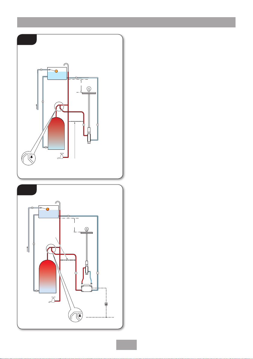
• Gravity systems.
• Pumped gravity systems.
• Fully modulating type combination boilers.
• Multi-point hot water heaters.
• Thermal storage.
• Unvented systems.
When installing this mixer with a Combination or
multi-point boiler, it may be necessary to install
flow regulation.
Check that the appliance is capable of delivering
hot water at a minimum switch-on flow rate
of 3 litres per minute. At flow rates between 3
and 8 litres per minute, the appliance must be
capable of raising the water temperature to 52°C
(minimum).
Water temperature at the inlet of the mixer valve
must remain relatively constant when flow rate
adjustments are made (refer to the appliance-
operating manual to confirm compatibility with
this mixer shower).
Where thermal store systems and instantaneous
gas water heaters are used, if excessive draw-
off take place the appliance may not be able to
maintain an adequate output temperature. This
could result in the shower temperature becoming
noticeably cooler.
Flow regulators can be fitted to the inlet
pipework with high-pressure water systems to
reduce flow rate and assist economy.
The hot supply temperature MUST remain a
minimum of 10°C hotter than the required blend
temperature for optimum performance.

Vertical bar mixer shower
4
*Fig.2 *(diagrammatic view – not to scale)
TYPICAL DOMESTIC INSTALLATIONS
Domestic gravity fed systems (fig.1)
The shower control MUST be fed from a cold
water cistern and hot water cylinder providing
nominally equal pressures. There must be a
minimum of one metre head of water. The
minimum head distance is measured from the
base of the cold water cistern to top of the
showerhead.
If valves are gravity fed, then supply pressure
should be verified to ensure conditions of use
are appropriate for the valve.
Pumped gravity fed systems (fig.2)
The shower control MUST be fed from a cold
water cistern and hot water cylinder providing
nominally equal pressures.
The mixer unit may be used with a gravity fed
system with a pump to boost pressures as shown;
please refer to the pump installation guide to
establish the minimum head requirements for
automatic operation of the pump
Hot water
cylinder
Mixer
Cold supply
Hot
supply
Alternative supply
(must be below
vent pipe tee)
Cold
water
mains
supply
Drain
valve
Gate
valve
Stop valve
Cold water
cistern
Minimum head
Other
draw-offs
Draw-off must point
down to avoid airlock
issues
Ring main
Isolating switch
or pull cord
switch (both
fused at 3A)
Service
valve
Service
valve
Pump
Hot water
cylinder
Cold supply
Hot supply
Alternative supply
(must be below
vent pipe tee)
Cold
water
mains
supply
Drain
valve
Gate
valve
Stop valve
Cold water
cistern
Other
draw-offs
Draw-off must point down
to avoid airlock issues
Service
valves
Mixer
Minimum head
*Fig.1 *(diagrammatic view – not to scale)

Vertical bar mixer shower
5
*Fig.3 *(diagrammatic view – not to scale)
*Fig.4 *(diagrammatic view – not to scale)
CH flow
Cold
mains
supply
Hot water
CH return
Service
valves
Mixer
Stop
tap
Expansion
vessel
Pressure
reducing valve
Combination
boiler
Instantaneous gas-heated systems,
e.g. combination boilers (fig.3)
The shower control MUST be installed with a
multi-point gas water heater or combination
boiler of a fully modulating design (i.e.
to maintain relatively stable hot water
temperatures).
A drop tight pressure reducing valve MUST
be fitted if the supply pressures exceed 5 bar
running.
An expansion vessel MAY be fitted, and regularly
maintained, to prevent the shower mixer
being damaged by excess pressures. This may
already be installed within the boiler (check with
manufacturer) and is in addition to the normally
larger central heating expansion vessel.
Unvented mains pressure systems (fig.4)
The shower control can be installed with an
unvented, stored hot water cylinder.
For systems with no cold water take off after the
appliance reducing valve, it will be necessary to
fit an additional drop tight pressure-reducing
valve when the mains pressure is over 5 bar. The
drop tight pressure reducing valve must be set at
the same value as the unvented package pressure
reducing valve.
Note: An additional expansion vessel may be
required if a second pressure-reducing valve is
installed. This does not apply to packages with a
cold take off after the pressure-reducing valve to
the cylinder.
Service
valves
Balanced cold mains supply
Cold mains supply
Mixer
Expansion
vessel
Pressure
reducing
valves Stop tap
Unvented
hot water
storage unit
Safety devices
not shown

Vertical bar mixer shower
6
Height of
showerhead
and shower
to suit user’s
requirement.
Handset can
be positioned
either side
of the rail.
Mains pressurised thermal store systems (fig.5)
Packages of this type, fitted with a tempering
valve (blender valve) can be used. A drop tight
pressure reducing valve MUST be fitted if the
supply pressures exceed 5 bar running.
An expansion vessel MUST be fitted, and
regularly maintained, to ensure, the unit, is
not damaged by excess pressures. This may
already be installed externally or internally within
the thermal store (check with thermal store
manufacturer).
INSTALLATION
PREPARING THE MIXER VALVE
Check the contents to make sure all parts are
present.
Before starting the mixer installation, make
sure all the openings on the valve are carefully
covered to stop ingress of any debris, etc. while
routing the supply pipework.
The shower valve is suitable for exposed
installation onto solid wall, a stud partition wall,
dry lined wall or fixing to a laminate cubicle or
panel.
SITING OF THE SHOWER AND
ACCESSORIES
Refer to (fig.6) for correct siting of the shower.
The mixer valve should be positioned, as
detailed, with all controls within comfortable
reach of the user.
The diverter can be rotated by 180˚ to allow the
handset to be positioned on either side of the
shower.
*Fig.6 *(diagrammatic view – not to scale)
*Fig.5 *(diagrammatic view – not to scale)
Flow
Return
Boiler
Blender
valve
Cold mains supply
Hot
water
Stop tap
Expansion
vessel
Pressure
reducing valve
Service
valves
Mixer

Vertical bar mixer shower
7
IMPORTANT
Consideration must be given for
the adequate ceiling space for the
installation of this shower. Please see
the dimensions shown in Fig.7.
Fig.7
All dimensions listed in this fitting book regarding the product and installation are approximate.
WARNING!
Riser pipework MUST not be cut.
The product may not perform within
stated specifications if altered.
Alteration may invalidate the warranty.
60mm between centres
360mm - minimum
79.5mm - ± 5mm

Vertical bar mixer shower
8
SUPPLY PIPE WORK
Complete the pipework to the shower area
having decided on the position of the shower
and direction of pipe entry (for example rising,
falling or rear entry)
The hot and cold water pipes should not
be permanently attached to the wall within
one metre of the valve, before installation is
complete, to allow for final adjustment of the
valve position.
Rear entry supplies
Using a spirit level, mark the route of incoming
hot and cold water supply pipes at a distance of
60mm (approximately) between centres (fig.8).
FITTING THE MIXER and PIPE
Note: The mixer bracket and the shower arm
bracket require secure fixing - (fig.9) gives an
example of the fixings required. The top bracket
shown in figure (fig.9a) MUST be secured to
a baton or noggin - fitting onto a plaster board
cavity is not acceptable.
The mixer bracket MUST also be supported by a
baton or noggin.
The mixer MUST be fitted vertically with the
HOT water going to the inlet, marked HOT, ‘H’
or with a red/orange label and connect the cold
water supply to the inlet marked
COLD, ‘C’ or blue label.
• Once the height and position of the mixer
and riser pipe have been established, the
mixer bracket will need to be installed.
Note: there must be at least 32mm from
the face of the mixer threads on the bracket
to the final tiled surface of the wall to allow
clearance for the top bracket installation.
IMPORTANT:
Make sure that all supply pipework has
been flushed through before fitting the
mixer.
WARNING!
Check there are no hidden cables or
pipes before drilling holes for wall
plugs. Use great care when using
power tools near water. The use of
a residual current device (RCD) is
recommended.
Fig.8
60mm

Vertical bar mixer shower
9
Fig.9
Bracket
Final tiled
surface
32mm
minimum
Fig.9a
Fig.9b
Note: there must be at least
32mm from the face of the
mixer threads to the final tiled
surface of the wall to allow
clearance for the top bracket
installation.
Illustrations are to give an example of the secure xings required.
This book does not have the scope to cover all installation options.

Vertical bar mixer shower
10
Fig.10 Fitting the mixer
Note: It is advisable to leak test the incoming
pipework before making good the wall.
• Fit the mixer to the bracket and tighten the
fittings.
Make sure that the mixers flow and diverter
controls are in the ‘OFF’ position -
see (fig.13 & 15).
• Turn on both of the water inlet supplies to the
mixer.
• Once it has been established that there are no
leaks, isolate the water supplies and remove
the mixer from the bracket.
• Make good the wall and fit the mixer face plate.
•
Fit the mixer to the bracket and tighten the fittings.
• Once the mixer is installed, distances to fit
the shower arm bracket should be checked.
The distance from the top of the outlet to
the centre of the bracket mounting plate is:
*79.5mm (±5mm) *Dimensions are approximate.
• Fit the top mounting bracket making sure it is
well supported by an internal baton or noggin
(fig.9a).
• Before fitting the riser pipe, the nut and olive
assembly, plus the mixer outlet top cover
should be fitted onto the riser pipe from the
top (fig.1O) - Note: if the items are fitted
from the bottom over the two sealing ‘O’ rings,
damage to the ‘O’ rings could occur and the
mixer leak from its top outlet.
• The riser pipe should then be placed into the
top of the mixer valve - do not tighten the
fittings yet.
• The shower arm will then need the riser pipe
screwing into the underneath of it, making
sure that the sealing washer is in place
(fig.10a)
• Once the riser pipe has been screwed into
shower arm, the arm will need to be guided
into the bracket.
• Tighten the nut and olive assembly onto the
mixer valve. Turn the grub screw into the mixer
outlet top cover until flush with the body.
• Secure the shower arm into the bracket with
the retaining grub screw.
Top of riser pipe
Mixer outlet
top cover
Nut and
olive
assembly
Bottom of riser pipe
10a

Vertical bar mixer shower
11
Fitting the fixed showerhead
Screw the fixed showerhead to the riser pipe.
Make sure the sealing washer is in place and
screw tight to seal the joint.
FINAL LEAK TESTING
Fit the hose to the outlet and direct it to waste.
Open the isolating valves to the shower and
check for leaks. Remedy any leaks found.
COMMISSIONING
Important: Make sure that all supply pipework
has been flushed through before commissioning.
Start the water flow by rotating the flow control
Make sure that both the hot and cold water
supplies are fully open and at (or near to) their
design temperature and pressures, and are within
the requirements as stated.
Make sure the temperature control is at the
maximum temperature setting.
Allow the shower to run at the maximum
temperature setting until the water temperature
has stabilised. Rotate the temperature control
until your desired maximum showering
temperature is reached.
The mixer has a temperature stop to prevent
accidental rotation to higher temperatures. This
is adjustable to provide a maximum temperature
of 35°C – 45°C and should be checked on site to
guarantee user safety.

Vertical bar mixer shower
12
TEMPERATURE ADJUSTMENT RANGE
The mixed water temperature can be adjusted
from cold through to a top limit (which can
be preset during installation – factory set
at approximately 38°C) with full anti-scald
protection throughout the range.
Adjusting the maximum temperature
override setting
• Remove the temperature control (bottom
of the mixer) by removing the end cap and
unscrewing the retaining screw (fig.11).
• Turn the flow control to full flow.
• Remove the lever and maximum temperature
stop and adjust the temperature valve
spindle until the desired maximum
temperature is achieved (fig.11) - turning
the spindle clockwise will Increase the
maximum temperature, turning the
spindle anti-clockwise will Decrease the
maximum temperature.
• When you are satisfied with the
temperature, turn the flow control off. Refit
in the reverse order with the maximum
temperature stop at the rear.
• The maximum temperature pin in the
control should be positioned as close as it
can be to the left hand side of the maximum
temperature stop.
• Once the lever is in place, secure with the
screw and replace the end cap.
Fig.11
Temperature
spindle
Bottom of
the mixer
Maximum
temperature
stop
Temperature
control
End view from
underneath the
mixer
Increase Decrease
Maximum
temperature
pin, in the
control
Wall

Vertical bar mixer shower
13
Fig.12
OPERATING THE SHOWER
• To start the mixer, rotate the On/Off flow
control (top lever) anti-clockwise until it stops
for maximum flow (fig.12).
• To stop the water flow, rotate the On/Off
flow control clockwise until it stops (fig.12).
• To adjust the water temperature, rotate
the temperature control (bottom lever)
– clockwise for hotter or anti-clockwise for
cooler (fig.13).
Flow control
Temperature
control
Fig.13
ON
OFF
COLDER
HOTTER

Vertical bar mixer shower
14
0.0
0.6
0.0 2.5
bar
l/min
Pressure/Flow rate
3 5.5 8 10.5 13 15.5 18 20.5 23 25.5 28
1.2
1.8
2.4
3.0
3.6
4.2
4.8
FLOW CHART
• Flow rate at 38°C
• Flow control fully open
• Open outlet
• No flow regulator fitted
APPROVALS
This mixer valve has been designed to comply with the requirements of: BS EN 1111
BS EN 1287
WRAS

Vertical bar mixer shower
15
DIMENSIONS
All dimensions listed in this fitting book regarding the product and installation are approximate.
42mm
60mm
204mm
64mm

Vertical bar mixer shower
16
SPARE PARTS
Ref. Description Part No.
1. Closure knob & flow knob 86003550
2. Trim and screw kit 83314180
3. Top outlet assembly 83314190
4. Thermostatic assembly 83314170
5. Flow valve 83314160
1
2
1
3
4
5

Vertical bar mixer shower
17
SPARE PARTS
Ref. Description Part No.
6. Coverplate 86003420
7. Inlet mounting bracket 86003410
8. Riser pipe, arm & bracket 86003430
9. Showerhead 88600006
6
7
8
9

Vertical bar mixer shower
18
MAINTENANCE
The following maintenance procedure must
be carried out for commercial and health care
premises, but is not necessarily required for
domestic installations.
Maintenance of the unit is required to give
continued performance after installation and that
it continues to provide scald prevention.
Note: A thermostatic mixing valve in need of
maintenance can be undetectable in normal
use and only becomes apparent when a
disruption occurs in the hot or cold water supply
temperatures or pressures.
The frequency of routine maintenance of the
internal of the valve will depend mainly on the
water supply condition. Experience of local
conditions will dictate the intervals for inspection
and in-service testing; guidance has been
given below which can be adjusted for local
requirements.
a) Initially check the filters for debris once every
three months and clean if necessary.
b) Perform a thermal shut off test
every three months, and check the
maximum temperature setting. See the
‘Commissioning’ section for the details of
this test and readjustment of the maximum
temperature setting if required.
c) If the maximum water temperature varies
by more than 2°C from the commissioned
setting then carry out the following checks
• Check the isolating valves are fully open.
• Check the internal surface for scaling.
If the body requires descaling then it should be
removed from the pipework to carry this work out
(all rubber parts must be removed before descaling).
• Check the function of the non-return valves
The non-return valves (NRVs) prevent cross-flow
between hot and cold supplies under unequal
pressure conditions. They are designed for long
life with no maintenance.
If these checks do not highlight the reason
for the temperature variation, then internal
components will require replacement; please see
the spare parts list.
WARNING!
DO NOT use ‘powerful’ abrasive or
solvent cleaning fluids when cleaning the
shower as they may damage the fittings.
Cleaning
Triton recommends that all products are cleaned
using warm, soapy water.
Do not use abrasive or aggressive chemical
cleaning products as this may affect the product
surface finish and invalidate your guarantee.
Cleaning the filters (fig.A)
It is advised that this should be carried out by a
qualified person.
• Turn off the water supplies before starting.
• Remove the mixer from the mixer bracket.
• Remoce the retaining clips in the hot and
cold inlets.
• Remove the none return valve and filter.
• Wash the filter thoroughly under running water,
use a suitable brush to remove all debris.
• Reassemble in reverse order.
Disinfection
Where chlorine is used for the disinfection
of water systems all relevant guidelines and
approved codes of practice must be strictly
followed. Failure to comply with the relevant
guidelines and approved codes of practice may
invalidate your guarantee.
Fig.A
Filter
None return
valve
Retaining clip
Mixer bracket
Other manuals for Thames
4
Table of contents
Other Triton Bathroom Fixture manuals

Triton
Triton T1 Si User manual

Triton
Triton T80 GSI User manual

Triton
Triton 86005760 User manual

Triton
Triton STYLE 3 User manual

Triton
Triton ENVI Setup guide

Triton
Triton T80ZFF FAST-FIT User manual

Triton
Triton ENVI GEENVF17 User manual

Triton
Triton T70 GSI User manual

Triton
Triton ENVI User manual

Triton
Triton OMNICARE GEOSRP81 User manual

Triton
Triton ZANTE 4 User manual

Triton
Triton T10 User manual

Triton
Triton DENE HI-FLO User manual

Triton
Triton Leona User manual

Triton
Triton ENVI User manual

Triton
Triton T300si User manual

Triton
Triton Spellbind User manual

Triton
Triton unichrome THAMES User manual

Triton
Triton T70Z User manual

Triton
Triton T100e Care User manual