Mandik FDMR Guide

www.mandik.co.uk
MANDÍK, a. s. • Dobříšská 550 • 267 24 Hostomice • Czech Republic • Tel.: +420 311 706 742 • E-Mail: [email protected]
Manufacturer
MANDIK UK Ltd • 130 Aztec West • Bristol BS32 4UB • United Kingdom • Tel.: +44 117 4526376 • E-Mail: [email protected]
Authorized representative
FDMR
Fire damper
Technical Documentation
Installation, Commissioning, Operation, Maintenance and Service Manual
TPM 165/22
Version 2022-12-20

FDMR - Fire damperPage 2 Version 2022-12-20
TPM 165/22
These technical specifications state a row of manufactured sizes and models of fire dampers FDMR.
It is valid for production, designing, ordering, delivery, maintenance and operation.
CONTENT
I. GENERAL.....................................................................................................................................................................................3
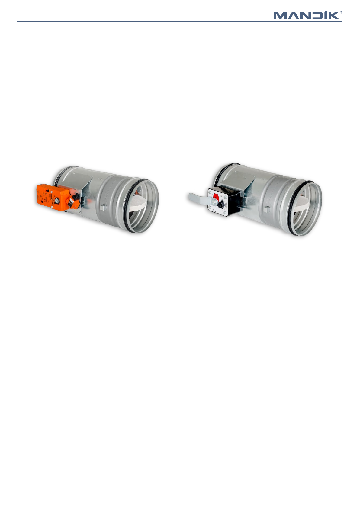
Description..............................................................................................................................................................................3
Design.....................................................................................................................................................................................4
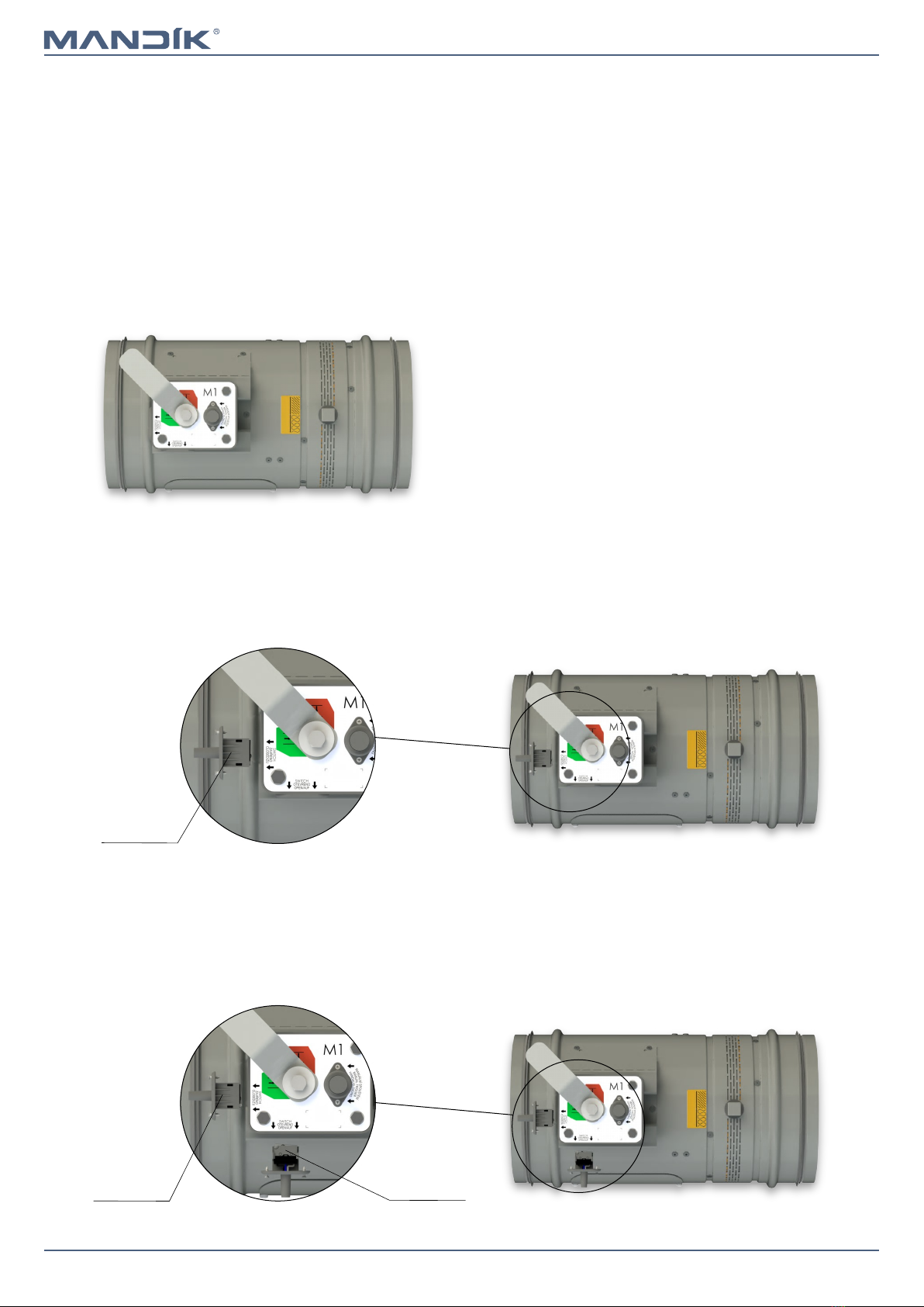
Design with mechanical control..........................................................................................................................................4
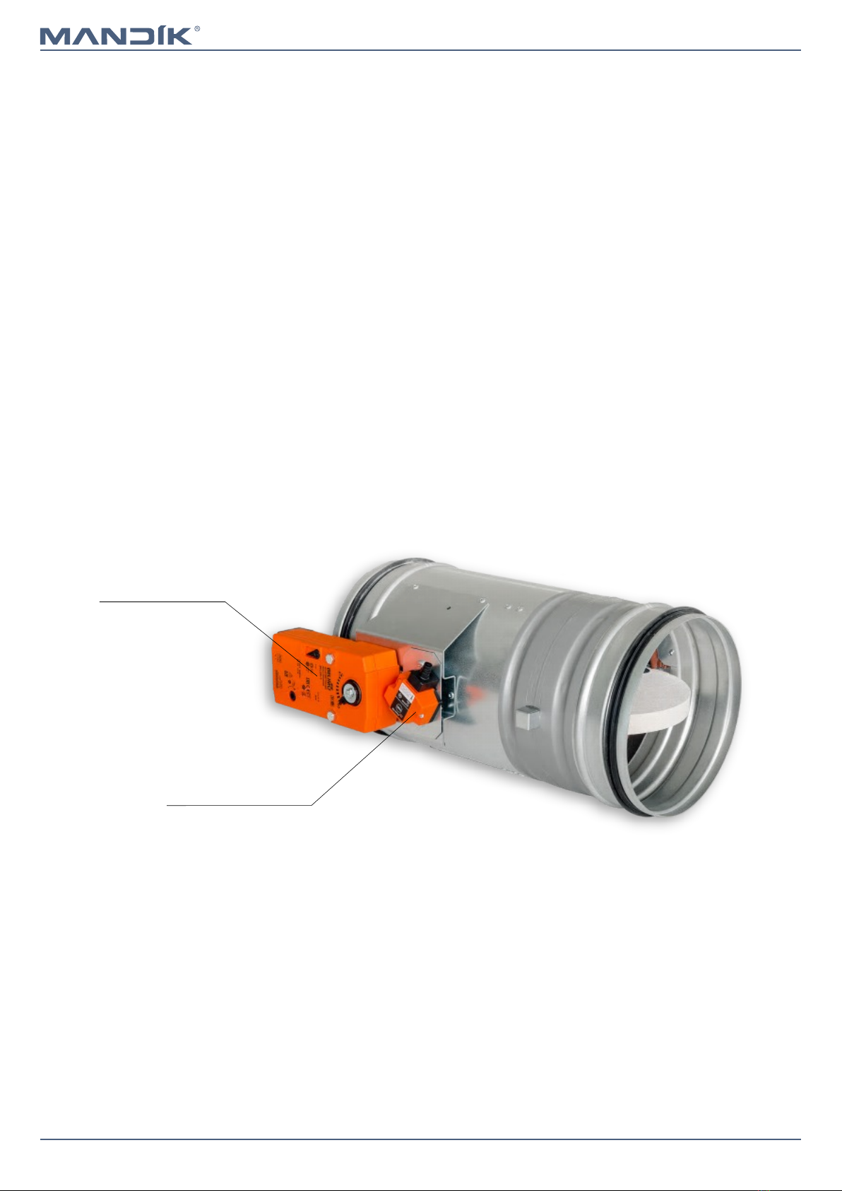
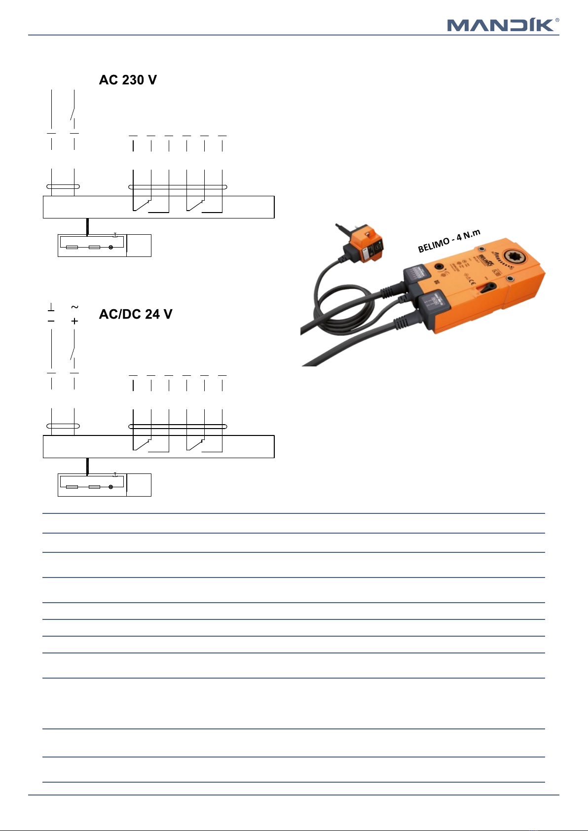
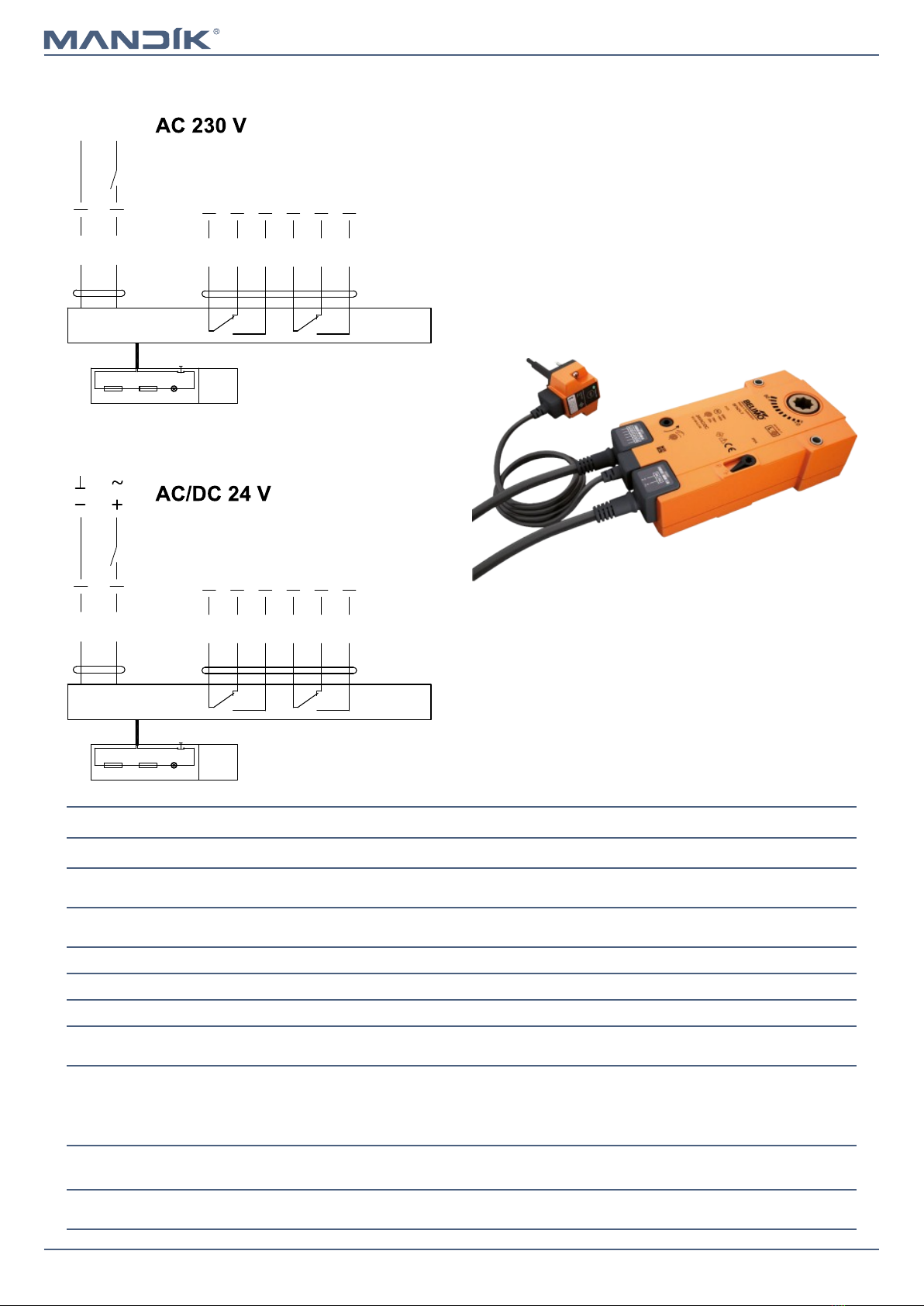
Design with actuating mechanism.......................................................................................................................................6
Communication and control module MDCM.....................................................................................................................11
Dimensions...........................................................................................................................................................................12
Technical parameters............................................................................................................................................................17
Placement and Assembly......................................................................................................................................................18
Statement of installations.....................................................................................................................................................20
Installation in solid wall construction................................................................................................................................21
Installation in gypsum wall construction...........................................................................................................................23
Installation in solid ceiling construction............................................................................................................................25
Suspension systems..............................................................................................................................................................26
Duct connection....................................................................................................................................................................28
II. TECHNICAL DATA.....................................................................................................................................................................29
Pressure loss.........................................................................................................................................................................29
Noise data.............................................................................................................................................................................30
III. MATERIAL, FINISHING.............................................................................................................................................................31
Material................................................................................................................................................................................31
IV. INSPECTION, TESTING.............................................................................................................................................................31
V. TRANSPORTATION AND STORAGE...........................................................................................................................................32
Logistic terms........................................................................................................................................................................32
VI. ASSEMBLY, ATTENDANCE AND MAINTENANCE......................................................................................................................32
Assembly...............................................................................................................................................................................32
Entry into service and revisions.........................................................................................................................................35
Spare parts.........................................................................................................................................................................36
VII. PRODUCT DATA.....................................................................................................................................................................37
Data label..............................................................................................................................................................................37
VIII. ORDERING INFORMATION....................................................................................................................................................37
Ordering key.........................................................................................................................................................................37

Page 3Version 2022-12-20 FDMR - Fire damper
TPM 165/22
I. GENERAL
Description
Working conditions
■Exact damper function is provided under the following conditions
■maximum air velocity 12 m/s
■underpressure max. -1200 Pa
■the air circulation in the whole damper section must be secured as steady on whole surface.
■Dampers can be installed in position with horizontal or vertical blade axis.
■Dampers can be installed in position with actuating mechanism on top or on the side of damper.
■Dampers are suitable for systems without abrasive, chemical and adhesive particles.
■Dampers are designed for macroclimatic areas with mild climate according to EN 60 721-3-3, class 3K22.
■Temperature in the place of installation is permitted to range from -30°C to +50°C.
Fire dampers are shutters in ducts of air-conditioning devices
that prevent spreading the fire and combustion products
from one fire segment to the other one by means of closing
the duct in the points of fire separating constructions.
Dampers blade automatically closes air duct using a shutting
spring or an actuating mechanism back spring. Closing spring
is released either by pushing of the button or by thermal fuse.
The back spring of the actuating mechanism is started when
the thermoelectrical starting mechanism BAT is activated,
when a reset button on BAT is pushed or when a power
supply of the actuating mechanism is stopped.
The damper is sealed with a silicon packing against smoke
penetration after closing the blade. At the same time, the
damper blade is bedded in a material which enlarges its
capacity and air proofs the air duct.
Dampers have one inspection hole, as the shutting device and
the inspection hole can be set to the most advantageous
position with respect to operation and handling of the control
device by turning the damper a little in case of the spiro
model of the dampers.
Damper FDMR with actuating mechanism Damper FDMR with mechanical control
Damper characteristics
■CE certified acc. to EN 15650
■Tested in accordance with EN 1366-2
■Classified acc. to EN 13501-3+A1
■External Casing leakage class min. C acc. to EN 1751
■Internal leakage min. class 3 acc. to EN 1751
■Cycling test in class C10000 acc. to EN 15650
■Corrosion resistant acc. to EN 15650
■Certificate of constancy of performance UKCA No. TBD* & UKNI No. TBD*
■Certificate of constancy of performance CE No. 1391-CPR-2021/0145
■Declaration of Perfomance UKCA & UKNI No. PM/FDMR/02/22/1
■Declaration of Perfomance CE No. PM/FDMR/01/22/1
■Hygienic assessment of fire dampers - Report No. 1.6/pos/19/19c * Document in process

FDMR - Fire damperPage 4 Version 2022-12-20
TPM 165/22
Design
Design with mechanical control
■Design with mechanical control with a thermal protective
fuse which actuates the shutting device, after the nominal
start temperature 72°C has been reached.
■Automatic initiation of the shutting device is not activated
if the temperature does not exceed 70°C.
■In case that other start temperatures are required,
thermal fuses with nominal start temperature +104°C or
+147°C can be supplied (this requirement must be
specified in the order).
Design .01
ATTENTION:
■Mechanisms are produced in five designs M1 to M5, dif-
ference is only in size of inner spring, which closes the fire
damper.
■For the size of fire dampers is always assigned the size of
mechanism → see page 17
■It is not recommended to use different size of mechanism,
than given by the manufacturer, otherwise, there is a risk
of fire damper destruction.
Design .01
■Design .01 with mechanical control can be complemented
with a limit switch signalling of the damper blade position
"CLOSED".
■Cable is connected directly to limit switch.
■Limit switch detail → see page 5
Design .11
Design .11
Limit switch
“CLOSED”
■Design .01 with mechanical control can be complemented
with a terminal switches signaling of the damper blade
position "CLOSED" and "OPEN".
■Limit switches are connected via damper casing, cables
are connected directly to limit switches.
■Limit switch detail → see page 5
Design .80
Design .80
Limit switch
“CLOSED”
Limit switch
“OPEN”

Page 5Version 2022-12-20 FDMR - Fire damper
TPM 165/22
Nominal voltage and maximal current AC 230V / 5A
Class of protection IP 67
Working temperature
-25°C … +120°C
Limit switch G905-300E03W1
This limit switch is possible to connect in following two versions
■CUT-OFF if the arm is moving … connect wire 1+2
■SWITCH-ON if the arm is moving … connect wire 1+4
1(COM) - black wire
2(NC) - gray wire
4(NO) - blue wire
Mechanical control
Fusible link

FDMR - Fire damperPage 6 Version 2022-12-20
TPM 165/22
Design with actuating mechanism
■The dampers are equipped by Belimo actuators with
spring return and thermoelectric activation device of BFL,
BFN or BF depending on the damper size (further mentio-
ned as „actuators“).
■After being connected to power supply 230V or AC/DC
24V, the actuating mechanism displaces the damper
blade into operation position "OPEN" and at the same
time it pre-stretches its back spring.
■When the actuating mechanism is under voltage, the
damper blade is in the position "OPEN" and the back
spring is pre-stretched.
■Time needed for full opening of the flap blade from the
position "CLOSED" to the position "OPEN" is maximum
120 sec. If the actuating power supply is cut off (due to
loss of supply voltage, or pushing the reset button on the
thermoelectrical starting mechanism BAT), the back
spring displaces the damper blade into the breakdown
position "CLOSED".
■The time of displacing the blade from the position "OPEN"
to the position "CLOSED" takes maximum 20 sec.
■In case that the power supply is restored again (the blade
can be in any position), the actuating mechanism starts to
re-displace the damper blade into the position "OPEN".
■A thermoelectrical starting mechanism BAT, which
contains two thermal fuses Tf1 and Tf2, is a part of the
actuating mechanism.
■These fuses are activated when temperature +72°C has
been exceeded (the fuse Tf1 when the temperature
around the damper and the fuses Tf2 when the
temperature inside the air-conditioning ducting has been
exceeded).
■After the thermal fuse Tf1 or Tf2 has been activated, the
power supply is permanently and irreversibly cut off and
the actuating mechanism, by means of the pre-stretched
spring, displaces the damper blade into the breakdown
position "CLOSED".
■Signalisation of damper blade position "OPEN" a "CLOSE"
is provided by two limit switches.
Design .40 and .50
Actuating mechanism
Thermoelectrical starting
mechanism BAT
Design .40 and .50

Page 7Version 2022-12-20 FDMR - Fire damper
TPM 165/22
Actuator BELIMO BFL 230-T
Actuator BELIMO BFL 24-T(-ST)
BELIMO - 4 N.m
Actuator BELIMO BFL 230-T, BFL 24-T(-ST)
Actuator BELIMO - 4 Nm BFL 230-T BFL 24-12(-ST)
Power voltage AC 230 V
50/60Hz
AC/DC 24 V
50/60Hz
Power consumption - motoring
- holding
3,5/5 W
1,1/2,1 W
2,5/4 W
0,8/1,4 W
Dimensioning 6,5/10 VA (Imax 4 A @ 5 ms) 4/6 VA (Imax 8,3 A @ 5 ms)
Protection class II III
Degree of protection IP 54
Running time - motor
- spring return
< 60 s
~ 20 s
Ambient temperature
- normal duty
- safety duty
- non-operating temperature
-30°C … +55°C
The safe position will be attained up to max. +75°C
-40°C … +55°C
Connection - motor
- auxiliary switch
cable 1 m, 2 x 0,75 mm² (BFL 24-T-ST) with 3-pin plug-in connectors
cable 1 m, 6 x 0,75 mm² (BFL 24-T-ST) with 6-pin plug-in connectors
Thermal trips duct outside temperature +72°C
duct inside temperature +72°C
S2S1 S3 S5S4 S6
2
1
<5° <80°
N L1
BAT
Tf Tf LED
S2S1 S3 S5S4 S6
2
1
<5° <80°
BAT
Tf Tf LED

FDMR - Fire damperPage 8 Version 2022-12-20
TPM 165/22
Actuator BELIMO BFN 24-T(-ST)
BELIMO - 9 N.m
Actuator BELIMO BFN 230-T, BFN 24-T(-ST)
Actuator BELIMO - 9 Nm BFN 230-T BFN 24-12(-ST)
Power voltage AC 230 V
50/60Hz
AC/DC 24 V
50/60Hz
Power consumption - motoring
- holding
3,5/5 W
1,1/2,1 W
2,5/4 W
0,8/1,4 W
Dimensioning 6,5/10 VA (Imax 4 A @ 5 ms) 4/6 VA (Imax 8,3 A @ 5 ms)
Protection class II III
Degree of protection IP 54
Running time - motor
- spring return
< 60 s
~ 20 s
Ambient temperature
- normal duty
- safety duty
- non-operating temperature
-30°C … +55°C
The safe position will be attained up to max. +75°C
-40°C … +55°C
Connection - motor
- auxiliary switch
cable 1 m, 2 x 0,75 mm² (BFN 24-T-ST) with 3-pin plug-in connectors
cable 1 m, 6 x 0,75 mm² (BFN 24-T-ST) with 6-pin plug-in connectors
Thermal trips duct outside temperature +72°C
duct inside temperature +72°C
Actuator BELIMO BFN 230-T
S2S1 S3 S5S4 S6
2
1
<5° <80°
N L1
BAT
Tf Tf LED
S2S1 S3 S5S4 S6
2
1
<5° <80°
BAT
Tf Tf LED

Page 9Version 2022-12-20 FDMR - Fire damper
TPM 165/22
Actuator BELIMO BF 230-TN
Actuator BELIMO BF 230-TN, BF 24-TN(-ST)
Actuator BELIMO - 40 Nm BF 230-TN BF 24-TN(-ST)
Power voltage AC 230 V
50/60Hz
AC/DC 24 V
50/60Hz
Power consumption - motoring
- holding
8 W
3 W
7 W
2 W
Dimensioning 12,5 VA (Imax 500 mA @ 5 ms) 10 VA (Imax 8,3 A @ 5 ms)
Protection class II III
Degree of protection IP 54
Running time - motor
- spring return
120 s
~ 16 s
Ambient temperature
- normal duty
- safety duty
- non-operating temperature
-30°C … +50°C
The safe position will be attained up to max. +75°C
-40°C … +50°C
Connection - motor
- auxiliary switch
cable 1 m, 2 x 0,75 mm²
cable 1 m, 6 x 0,75 mm²
(BF 24-T-ST) with plug-in connectors
Thermal trips Tf1: duct outside temperature Duct +72°C
Tf2/Tf3: duct intside temperature Duct +72°C
BELIMO - 40 N.m
Actuator BELIMO BF 24-TN (-ST)
S2S1 S3 S5S4 S6
2
1
<5° <80°
N L1
BAT
Tf Tf LED
S2S1 S3 S5S4 S6
2
1
<5° <80°
BAT
Tf Tf LED

FDMR - Fire damperPage 10 Version 2022-12-20
TPM 165/22
Thermoelectrical starting mechanism BAT 72
Power voltage AC/DC 24 V
50/60Hz
Rated current 1 A
AC/DC throughput resistance <1 Ω
Protection class III
Degree of protection IP 54
Probe length 65 mm
Ambient temperature
Storage temperature
Ambient humidity
-30°C … +50°C
-40°C … +50°C
Max. 95% RH, non-condensing
Connection supply Cable 1 m, 2 x 0.5 mm², Betaflam cable heatresistant up to 145°C
Response temperature thermal fuse Duct inside temperature 72°C
Duct outside temperature 72°C
Thermoelectrical starting mechanism BAT
■If the thermal fuse Tf1 breaks (for a temperature close to
the fire damper), it is necessary to replace the actuating
mechanism. Thermoelectric starting mechanism BAT is
integral part of the actuating mechanism.
■If the thermal fuse Tf2 (for temperature in the duct) is
interrupted, it is enough to replace only the spare part
ZBAT72.
■When one of the thermal fuses responds, the supply
voltage is interrupted permanently and irreversibly.
■The function (interruption of the supply voltage) can be
checked by pressing the test button.
■Installation is carried out with the pre-assembled, self-
drilling and self-tapping screws.
Temperature thermal fuse
Spare parts are only supplied on the basis of an order.
BELIMO ZBAT 72
Black (BK) = 72°C (standard)

Page 11Version 2022-12-20 FDMR - Fire damper
TPM 165/22
■The MDCM damper control module is connected on a bi
directional communication loop back to a control panel, typically
located at the FCC.
■Each MDCM has a 230v local spur to power the damper actuator.
■Up to 96x MDCM's can be connected on one loop and multiple
loops can be incorporated.
■This accessory is only required with MANDIK control systems.
OVERRIDE MDCM
6 5 4 3 2 1 L N N L+ +
MOTOR POWERCOMMS
S S - -
F1
S5
S6
S4
S3
S2
S1
COMMS
OPEN
CLOSED
COMMAND
L
L
N L
+
S90C CONTROLLER
S90 mounted in an addressablesmoke
control damper control panel to BS
ISO 21927-9
Cable glands
Comms cable
Damper control module PCB mounted on plastic rail
Earth stud
230v 50hz 3A fused supply (by others)
Switches 6 core
Drive open / close 230v
Damper actuator
Power
Comms IN
Comms OUT
MDCM
160mm x 160mm x 62mm deep steel
enclosure powder coated red - IP 54
-
56
+-
78
S E
Communication and control module MDCM

FDMR - Fire damperPage 12 Version 2022-12-20
TPM 165/22
Dimensions
SPIRO design with mechanical control
1 Damper casing
2 Mechanics
3 Damper blade
4
Inspection hole covering
5 Sensor sticker
6 Hole for camera
300
50
120
110
400
180
50
ØD-2
120
300
50 50
130
130
110
400
ØD-2
300
50
120
50
110 136
400
39
ØD-2

Page 13Version 2022-12-20 FDMR - Fire damper
TPM 165/22
400
130
130
110
ØD
120
400
ØD
110 136
39
120
400
110 180
ØD
120
FLANGE design with mechanical control
1 Damper casing
2 Mechanics
3 Damper blade
4
Inspection hole covering
5 Sensor sticker
6 Hole for camera
Ød
[mm]
Ød1
[mm]
Ød2
[mm]
n
number of holes
in the flange
100 130 10 4
125 155 10 8
160 195 10 8
180 215 10 8
200 235 10 8
225 260 10 8
250 285 10 8
280 315 10 8
300 335 10 8
315 350 10 12
355 390 10 12
400 445 12 12
450 495 12 12
500 545 12 16
560 605 12 16
600 650 12 16
630 680 12 16
710 760 12 20
800 860 12 20
Ød
Ød1
Ød2/n

FDMR - Fire damperPage 14 Version 2022-12-20
TPM 165/22
300
50 50
130
130
110
400
X
ØD-2
300
50 50
110 136
400
39
X
ØD-2
300
50
X
110
400
180
50
ØD-2
SPIRO design with actuating mechanism
1 Damper casing
2 Actuating mechanism
3 Damper blade
4 Inspection hole covering
5
BAT thermoelectrical starting mechanism
6 Hole for camera
X=53 mm (BFL) *
X=72 mm (BFN) *
X=78 mm (BF) *
* Assignment of actuating mechanisms to individual sizes → see page 17

Page 15Version 2022-12-20 FDMR - Fire damper
TPM 165/22
Ød
[mm]
Ød1
[mm]
Ød2
[mm]
n
number of holes
in the flange
100 130 10 4
125 155 10 8
160 195 10 8
180 215 10 8
200 235 10 8
225 260 10 8
250 285 10 8
280 315 10 8
300 335 10 8
315 350 10 12
355 390 10 12
400 445 12 12
450 495 12 12
500 545 12 16
560 605 12 16
600 650 12 16
630 680 12 16
710 760 12 20
800 860 12 20
Ød
Ød1
Ød2/n
400
130
130
110
X
ØD
400
ØD
110 136
39
X
400
X
110 180
ØD
FLANGE design with actuating mechanism
1 Damper casing
2 Actuating mechanism
3 Damper blade
4 Inspection hole covering
5
BAT thermoelectrical starting mechanism
6 Hole for camera
X=70 mm (BFL - DN 100 ÷ DN 315) *
X=53 mm (BFL - DN 355 ÷ DN 400) *
X=72 mm (BFN) *
X=78 mm (BF) *
* Assignment of actuating mechanisms to individual sizes → see page 17

FDMR - Fire damperPage 16 Version 2022-12-20
TPM 165/22
Damper blade overlaps
■Open damper blade overlaps the damper body by the value “c” or “a”. These values are specified in chapter Technical
parameters → see page 17
■Dimensions of damper connecting flanges are in accordance with EN 12 0505.
Values "a" and "c" has to be respected when projecting related air-conditioning ducts.
ca
c a
Fire damper with installation brackets
■Weight of installation brackets is 0,04 kg.
■Number of brackets for individual sizes → see page 17
damper SPIRO damper FLANGE

Page 17Version 2022-12-20 FDMR - Fire damper
TPM 165/22
Technical parameters
Nominal size
ØD
[mm]
Damper blade
overlaps Weight
Number of
installation
brackets *
Effective
area Sef
[m2]
Blade
thickness
[mm]
Actuating
mechanism
Mechanical
control
a
[mm]
c
[mm]
Mechanical
control
[kg]
Actuating
mechanism
[kg]
100 - - 2,9 3,1 2 0,0031 20 BFL M1
125 - - 3,2 3,4 2 0,0062 20 BFL M1
140 - - 3,3 3,5 2 0,0085 20 BFL M1
150 - - 3,5 3,7 2 0,0103 20 BFL M1
160 - - 3,6 3,8 2 0,0123 20 BFL M1
180 - - 4 4,2 3 0,0166 20 BFL M1
200 - - 4,3 4,5 3 0,0215 20 BFL M1
225 - - 4,8 5 3 0,0275 25 BFL M1
250 - 9 5,1 5,3 3 0,0354 25 BFL M2
280 - 24 5,7 5,9 3 0,0462 25 BFL M2
300 - 34 6,2 6,4 3 0,0542 25 BFL M2
315 - 42 6,5 6,7 3 0,0606 25 BFL M2
350** - 59 8,1 8,2 3 0,0751 30 BFL M2
355 - 62 8,2 8,3 3 0,0776 30 BFL M2
400 - 84 9,3 9,4 3 0,1015 30 BFL M2
450 - 109 10,4 10,8 3 0,1318 30 BFN M3
500 - 134 11,7 12,1 3 0,1661 30 BFN M3
560 - 164 13,4 13,8 3 0,2123 30 BFN M3
600 4 184 14,5 16,7 3 0,2463 30 BF M4
630 19 199 15,5 17,7 3 0,2735 30 BF M4
710 59 239 27 29,2 4 0,3446 40 BF M4
800 104 284 32,4 34,6 4 0,4448 40 BF M5
* Weight of installation brackets is 0,04 kg.
** Only spiro design SL or SK, can be ordered → see page 37

FDMR - Fire damperPage 18 Version 2022-12-20
TPM 165/22
■The fire dampers are suitable for installation in arbitrary
position in vertical and horizontal passages of fire separ-
ating structures. The damper assembly procedures must
be done so that all load transfer from the fire separating
constructions to the damper body is absolutely excluded.
The back-to-back air-conditioning ducting must be susp-
ended or supported so that all load transfer from the
back-to-back ducting to the damper flanges is absolutely
excluded. The gap between the installed damper and the
building structure must be perfectly filled with approved
material all over its volume.
■To provide the necessary space for access to the control
device, all other items must be situated at least 350 mm
from the control parts of the damper. At least one inspec-
tion hole must be accessible.
■The damper must be installed so that the damper blade
(in closed position) is situated in the fire separating
structure - marked by the label BUILT-IN EDGE on the
damper body. If such solution is not possible, the ducting
between the fire separating structure and the damper
blade must be protected according to the certified install-
ation method → see pages 21 to 25
■During the installation and plastering process, the control
mechanism must be protected (covered) against damage
and pollution. The damper body should not be deformed
during bricking in. Once the damper is built in, the damper
blade should not grind on the damper body during
opening or closing.
■The distance between the fire damper and the structure
(wall, ceiling) must be 75 mm at the minimum. If two or
more dampers are to be installed in one fire separating
structure, the distance between adjacent dampers must
be 200 mm at the minimum, according to EN 1366-2.
The distance between the fire damper and the construction
■minimum distance 200 mm between dampers installed in the duct;
■minimum distance 75 mm between damper and construction (wall/ceiling).
■This is the EN 1366-2 test standard distances. They are
considered as minimum. Actual location should be
based on wall manufacturers requirements.
■Always consult the wall manufacturers specific guide-
lines for deflection heads, penetration size, location to
other services, fire stopping and load bearing capacity.
■No other services should pass through the dampers
building work opening.
■For lightweight walls always consult the wall manufac-
turer specific guidelines for penetrations sizes and dis-
tances.
Placement and Assembly

Page 19Version 2022-12-20 FDMR - Fire damper
TPM 165/22
300
190 5050 50
400
400
240 50 110
Built in edge
"Wall BUILT IN EDGE sticker" indicates the recommended edge of installation of fire damper into the fire partition structure (wall).
The damper must be installed so that the entire damper blade - in the closed position - is located inside the fire separating structure (wall)
and at the same time the control mechanism and inspection openings are freely accessible.
Built in edge
X
Damper SPIRO
Built in edge
X
Damper FLANGE

FDMR - Fire damperPage 20 Version 2022-12-20
TPM 165/22
Statement of installations
Placement
wall/ceiling
min. thickness
[mm]
Filling of space
between damper
and wall
Fire resistance Page
In solid wall
construction
100
Mortar or gypsum EI 120 (ve i↔o) S 21
Ablative Coated Batt EI 90 (ve i↔o) S 22
In gypsum wall construction
Mortar or gypsum EI 120 (ve i↔o) S 23
Ablative Coated Batt EI 90 (ve i↔o) S 24
In solid ceiling construction 150 Mortar or gypsum EI 120 (ho i↔o) S 25
■The fire damper can be integrated into a solid wall
construction made e.g. of normal concrete/masonry,
porous concrete with minimum thickness 100 mm or into
solid ceiling construction made e.g. of normal concrete
with minimum thickness 150 mm.
■The fire damper can be integrated into a gypsum wall
construction with fire classification EI120 or EI 90.
■The fire damper can also be integrated outside the wall
construction. Duct and the damper part between the wall
construction and the damper blade (labelled with BUILT
IN EDGE on the protective covering) must be protected
with fire-fighting insulation.
Examples of fire damper installing
Dimensions of installation opening
Mortar or gypsum / Ablative Coated Batt
Dimensions of installation opening
Mortar or gypsum
* Mortar or gypsum
■min. A(B)+80
■max. A(B)+300
Ablative Coated Batt
■min. A(B)+80
■max. A(B)+260
** Mortar or gypsum
■min. A(B)+80
■max. A(B)+300
Other manuals for FDMR
3
Table of contents
Other Mandik Fire And Smoke Damper manuals